Rockwell Automation Allen-Bradley CompactLogix 1769-L32E Installation Instructions Manual
Hide thumbs
Also See for Allen-Bradley CompactLogix 1769-L32E:
- Installation instructions manual (41 pages) ,
- User manual (20 pages)
Table of Contents
Advertisement
Quick Links
Installation Instructions
CompactLogix Controllers
Catalog Numbers 1769-L32E, 1769-L35E
Topic
Important User Information
Verify Compatibility
Before You Begin
Connect the 1769-BA Battery
Install a CompactFlash Card (optional)
Assemble the System
Mount the System
Make RS-232 Connections to the Controller
Make Ethernet Connections to the Controller
Install the Appropriate EDS Files
Load the Controller Firmware
Select the Controller's Operating Mode
Controller Status Indicators
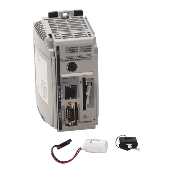
Use this document as a guide to install the CompactLogix™ controller, which must be the
leftmost module in the first bank of the system. The 1769-L32E and 1769-L35E controllers
offer an integrated EtherNet/IP port.
Page
2
5
6
6
8
8
10
12
14
19
19
22
23
Advertisement
Table of Contents

Related Manuals for Rockwell Automation Allen-Bradley CompactLogix 1769-L32E


Summary of Contents for Rockwell Automation Allen-Bradley CompactLogix 1769-L32E
- Page 1 Installation Instructions CompactLogix Controllers Catalog Numbers 1769-L32E, 1769-L35E Topic Page Important User Information Verify Compatibility Before You Begin Connect the 1769-BA Battery Install a CompactFlash Card (optional) Assemble the System Mount the System Make RS-232 Connections to the Controller Make Ethernet Connections to the Controller Install the Appropriate EDS Files Load the Controller Firmware Select the Controller’s Operating Mode...
-
Page 2: Important User Information
Rockwell Automation, Inc. cannot assume responsibility or liability for actual use based on the examples and diagrams. No patent liability is assumed by Rockwell Automation, Inc. with respect to use of information, circuits, equipment, or software described in this manual. -
Page 3: Environment And Enclosure
CompactLogix Controllers Environment and Enclosure WARNING: This equipment is intended for use in a Pollution Degree 2 industrial environment, in overvoltage Category II applications (as defined in IEC publication 60664-1), at altitudes up to 2000 meters (6562 ft) without derating. This equipment is considered Group 1, Class A industrial equipment according to IEC/CISPR Publication 11. -
Page 4: North American Hazardous Location Approval
CompactLogix Controllers North American Hazardous Location Approval The following information applies when operating Informations sur l’utilisation de cet équipement en this equipment in hazardous locations. environnements dangereux. Products marked "CL I, DIV 2, GP A, B, C, D" are suitable for Les produits marqués "CL I, DIV 2, GP A, B, C, D"... -
Page 5: Verify Compatibility
CompactLogix Controllers European Hazardous Location Approval European Zone 2 Certification (The following applies when the product bears the Ex or EEx Marking) This equipment is intended for use in potentially explosive atmospheres as defined by European Union Directive 94/9/EC and has been found to comply with the Essential Health and Safety Requirements relating to the design and construction of Category 3 equipment intended for use in potentially explosive atmospheres, given in Annex II to this Directive. -
Page 6: Before You Begin
CompactLogix Controllers Before You Begin Consider the following when planning your CompactLogix system: • The CompactLogix controller is always the leftmost module in the system. • The controller must be within four modules of the system power supply. Some I/O modules may be up to eight modules away from the power supply. - Page 7 CompactLogix Controllers WARNING: When you connect or disconnect the battery, an electrical arc can occur. This could cause an explosion in hazardous location installations. Be sure that power is removed or the area is nonhazardous before proceeding. For safety information on the handling of lithium batteries, including handling and disposal of leaking batteries, see Guidelines for Handling Lithium Batteries Technical Data, publication AG-5.4NOV04.
-
Page 8: Install A Compactflash Card (Optional)
CompactLogix Controllers Install a CompactFlash Card (optional) ATTENTION: Do not remove the CompactFlash card while the controller is reading from or writing to the card, as indicated by a flashing green CF status indicator. This could corrupt the data on the card or in the controller, as well as corrupt the latest firmware in the controller. - Page 9 CompactLogix Controllers Refer to the illustration when installing a controller. 44733 1. Disconnect line power. 2. Check that the lever of the adjacent module (A) is in the unlocked (fully right) position. 3. Use the upper and lower tongue-and-groove slots (B) to secure the modules together. 4.
-
Page 10: Mount The System
CompactLogix Controllers Mount the System ATTENTION: During panel or DIN-rail mounting of all devices, be sure that all debris (such as metal chips or wire strands) is kept from falling into the controller. Debris that falls into the controller could cause damage while the controller is energized. -
Page 11: Ground The Wiring
CompactLogix Controllers Ground the Wiring ATTENTION: This product is grounded through the DIN rail to chassis ground. Use zinc-plated yellow-chromate steel DIN rail to assure proper grounding. The use of other DIN rail materials (such as aluminum or plastic) that can corrode, oxidize, or are poor conductors, can result in improper or intermittent grounding. -
Page 12: Mount The Controller On The Din Rail
CompactLogix Controllers Mount the Controller on the DIN Rail The controller can be mounted on the following DIN rails: • EN 50 022 - 35 x 7.5 mm (1.38 x 0.30 in.) • EN 50 022 - 35 x 15 mm (1.38 x 0.59 in.) ATTENTION: This product is grounded through the DIN rail to chassis ground. -
Page 13: Default Serial Configuration
CompactLogix Controllers RS-232 Cable 9-pin, Male D-shell Straight Cable End 9-pin, Female 1 CD D-shell Right-angle 1 CD 2 RDX 2 RDX Cable End 3 TXD 3 TXD 4 DTR 4 DTR COMMON COMMON 6 DSR 6 DSR 7 RTS 7 RTS 8 CTS 8 CTS... -
Page 14: Use The Channel 0 Default Communication Push Button
CompactLogix Controllers Use the Channel 0 Default Communication Push Button The Channel 0 default communication push button is on the 44736 front of the controller in the lower right corner as shown in the illustration. Use the Channel 0 default communication push button to change from the user-defined communication configuration to the default communication mode. -
Page 15: Assign An Ip Address
CompactLogix Controllers Connect the RJ-45 connector of the Ethernet cable to the Ethernet port (top port) on the controller. ATTENTION: Do not plug a DH-485 network cable or a NAP cable into the Ethernet port. Undesirable behavior or damage to the port may result. 8 ------ NC 7 ------ NC 6 ------ RD-... - Page 16 CompactLogix Controllers 4. Click OK. In the BOOTP Request History dialog box, you see the hardware addresses of devices issuing BOOTP requests. 5. Double-click the hardware address of the device you want to configure. The hardware address is on the sticker on the left-side circuit board of the controller next to the battery.
- Page 17 CompactLogix Controllers 7. Click OK. 8. To permanently assign this configuration to the device, highlight the device and click Disable BOOTP/DHCP. When you cycle power, the device uses the configuration you assigned and does not issue a BOOTP request. Use RSLinx Software to Set the IP Address You can use RSLinx software, version 2.41 or later, to set the IP address.
- Page 18 CompactLogix Controllers 6. Select the Port Configuration tab. 7. Click the appropriate radio button to choose the Network Configuration type. 8. Enter the IP address, network (subnet) mask, and gateway address (if needed). Use RSLogix 5000 Software to Set the IP Address You can use RSLogix software to set the IP address.
-
Page 19: Install The Appropriate Eds Files
CompactLogix Controllers 7. Click Apply. 8. Click OK. This sets the IP address in the hardware. This IP address should be the same IP address you assigned under the General tab. Install the Appropriate EDS Files If you have RSLinx software, version 2.42 or later, the most current EDS files were installed with the software. -
Page 20: Use The Controlflash Utility To Load Firmware
CompactLogix Controllers Follow these steps to download firmware from the support website. 1. On the Rockwell Automation Support Page, click Software Updates, Firmware and Other Downloads under the Other Tools heading. 2. Click Firmware Updates. 3. Select the appropriate firmware update. - Page 21 CompactLogix Controllers 1. Make sure the appropriate network connection is made and your network driver is configured in RSLinx software. 2. Use RSLogix 5000 programming software to create a controller project. 3. Click RSWho to specify the controller path. 4. Select your controller and click Download. You may also choose to click Update Firmware to complete this process.
-
Page 22: Select The Controller's Operating Mode
CompactLogix Controllers Select the Controller’s Operating Mode Use the keyswitch on the front panel of the controller to determine the controller’s operating mode. Keyswitch Description Position • Upload projects. • Run the program and enable outputs. • You cannot create or delete tasks, programs, or routines. You cannot create or delete tags or edit online while the keyswitch is in the Run position. -
Page 23: Controller Status Indicators
Cycle power to the chassis. When the controller is ready, download the project and change to Run mode. If the OK status indicator remains solid red, contact your Rockwell Automation representative or local distributor. Solid green Controller is OK. - Page 24 CompactLogix Controllers RS-232 Serial Port Status Indicators (Channel 0) Indicator Status Description DCH0 Channel 0 is configured differently than the default serial configuration. Solid green Channel 0 has the default serial configuration. No RS-232 activity. Flashing green RS-232 activity. CompactFlash Card Status Indicator ATTENTION: Do not remove the CompactFlash card while the controller is reading from or writing to the card, as indicated by a flashing green CF status indicator.
-
Page 25: Module Status (Ms) Indicator
CompactLogix Controllers Module Status (MS) Indicator Condition Status Description No power The controller does not have power. Check the controller power supply. Flashing green Standby The controller does not have an IP address and is operating in BOOTP mode. Verify that the BOOTP server is running. Solid green The controller is operating correctly. -
Page 26: Link Status (Lnk) Indicator
Industrial Automation Wiring and Grounding Guidelines, Ground and wire Allen-Bradley programmable publication 1770-4.1 controllers You can view or download publications at http://www.rockwellautomation.com/literature/. To order paper copies of technical documentation, contact your local Allen-Bradley® distributor or Rockwell Automation sales representative. Publication 1769-IN020E-EN-P - December 2011... - Page 27 CompactLogix Controllers Notes: Publication 1769-IN020E-EN-P - December 2011...
-
Page 28: Rockwell Automation Support
Rockwell Automation representative. New Product Satisfaction Return Rockwell Automation tests all of its products to ensure that they are fully operational when shipped from the manufacturing facility. However, if your product is not functioning and needs to be returned, follow these procedures.
Need help?
Do you have a question about the Allen-Bradley CompactLogix 1769-L32E and is the answer not in the manual?
Questions and answers