
Related Manuals for Rockwell Automation Allen-Bradley MicroLogix 1400


Summary of Contents for Rockwell Automation Allen-Bradley MicroLogix 1400
- Page 1 MicroLogix 1400 Programmable Controllers Bulletin 1766 Controllers and 1762 Expansion I/O User Manual...
- Page 2 Labels may be on or inside the equipment, such as a drive or motor, to alert people that surfaces may reach dangerous temperatures. Rockwell Automation, Allen-Bradley, SLC 5/02, SLC 5/03, PLC-5, MicroLogix, SLC 500, RSLogix, RSLinx, RSLogix 500, RSLogix Micro, and TechConnect are trademarks of Rockwell Automation, Inc.
-
Page 3: Table Of Contents
Table of Contents Preface Who Should Use this Manual......11 Purpose of this Manual ......11 Related Documentation . - Page 4 Table of Contents Panel Mounting ....... 37 1762 Expansion I/O Dimensions ..... 38 Mounting 1762 Expansion I/O .
- Page 5 Table of Contents Connecting the Communication Cable to the DH-485 Connector ........82 Grounding and Terminating the DH-485 Network .
- Page 6 Table of Contents Configuring the Ethernet Port ....139 Configuring Ethernet Protocol Setup ....142 Using Trim Pots .
- Page 7 Error Codes ....... . . 207 Calling Rockwell Automation for Assistance ... . 208...
- Page 8 Table of Contents Appendix E Connecting to Networks via RS-232 Communication Interface ....225 RS-485 Communication Interface ....225 RS-232/RS-485 Interface DF1 Full-Duplex Protocol .
- Page 9 Table of Contents Download a User Program via DNP3 Network ..307 Default Directories and Files..... 308 Generating *.IMG file using RSLogix 500/RSLogix Micro.
- Page 10 Table of Contents Glossary Index Publication 1766-UM001A-EN-P - October 2008...
-
Page 11: Preface
• the purpose of this manual • related documentation • conventions used in this manual • Rockwell Automation support Who Should Use this Use this manual if you are responsible for designing, installing, programming, or troubleshooting control systems that use MicroLogix Manual 1400 controllers. -
Page 12: Related Documentation
Related Documentation The following documents contain additional information concerning Rockwell Automation products. To obtain a copy, contact your local Rockwell Automation office or distributor. Resource Description MicroMentor: Understanding and Applying Micro Information on understanding and applying micro controllers. Programmable Controllers 1761-MMB MicroLogix 1400 Programmable Controllers Instruction Information on the MicroLogix 1400 Controllers instruction set. -
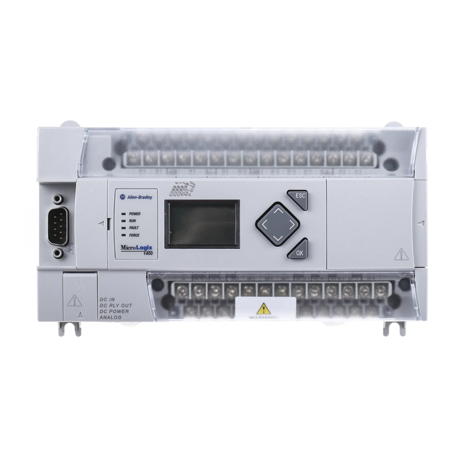
Page 13: Hardware Overview
Chapter Hardware Overview Hardware Features combination RS-232/485 communication port, an Ethernet port, and a non-isolated RS-232 communication port. Each controller supports 32 discrete I/O points(20 digital inputs, 12 discrete outputs) and 6 analog I/O points(4 analog inputs and 2 analog outputs : 1766-L32BWAA, -AWAA and -BXBA only). -
Page 14: Component Descriptions
Hardware Overview Comm port 1 - RJ45 connector Comm port 0 - 8-pin mini DIN RS-232C/RS-485 connector Controller Input and Output Description Catalog Number Description Input User Embedded Embedded Comm. Ports Power Power Discrete I/O Analog I/O 1 Ethernet 1 RS232 1766-L32AWA None 20 120VAC Inputs... -
Page 15: 1762 Expansion I/O
1766-MM1 Memory Module 44536 1762 Expansion I/O Appendix H to determine how much heat a certain combination generates. 1762 Expansion I/O 1762 Expansion I/O 1762 Expansion I/O Connected to MicroLogix 1400 Controller 44581 44563... -
Page 16: Communication Cables
Hardware Overview 1762-IQ8 8-Point Sink/Source 24V DC Input Module 1762-IQ16 16-Point Sink/Source 24V DC Input Module 1762-OA8 8-Point 120/240V AC Triac Output Module 1762-OB8 8-Point Sourcing 24V DC Output Module 1762-OB16 16-Point Sourcing 24V DC Output Module 1762-OW8 8-Point AC/DC Relay Output Module 1762-OW16 16-Point AC/DC Relay Output Module 1762-OX6I... -
Page 17: Programming
ATTENTION Programming Communication Options • operator interfaces, personal computers, etc. using DF1 Full Duplex point-to-point • a DH-485 network • a DF1 Radio Modem network • a DF1 half-duplex network as an RTU Master or RTU Slave • a Modbus network as an RTU Master or RTU Slave •... - Page 18 Channel 0 combo port provides both RS-232 and RS-485 isolated connections. The appropriate electrical interface is selected through your choice of communication cable. The existing MicroLogix 1761 communication cables provide an interface to the RS-232 drivers. The 1763-NC01 cable provides an interface to the RS-485 drivers. The controller may also be connected to serial devices, such as bar code readers, weigh scales, serial printers, and other intelligent devices, using ASCII.
-
Page 19: Installing Your Controller
Installing Your Controller This chapter shows you how to install your controller. The only tools you require are a flat or Phillips head screwdriver and drill. Topics include: • agency certifications • compliance to European Union Directives • installation considerations •... -
Page 20: Emc Directive
Installing Your Controller EMC Directive This product is tested to meet Council Directive 2004/108/EC Electromagnetic Compatibility (EMC) and the following standards, in whole or in part, documented in a technical construction file: • EN 61131-2; Programmable Controllers (Clause 8, Zone A & B) •... -
Page 21: Safety Considerations
Installing Your Controller guidelines, see the Industrial Automation Wiring and Grounding Guidelines publication 1770-4.1. Electrostatic discharge can damage semiconductor devices inside the ATTENTION controller. Do not touch the connector pins or other sensitive areas. Vertical mounting of the controller is not supported due to heat ATTENTION build-up considerations. -
Page 22: Hazardous Location Considerations
Installing Your Controller Hazardous Location Considerations This equipment is suitable for use in Class I, Division 2, Groups A, B, C, D or non-hazardous locations only. The following WARNING statement applies to use in hazardous locations. EXPLOSION HAZARD WARNING • Substitution of components may impair suitability for Class I, Division 2. -
Page 23: Disconnecting Main Power
Installing Your Controller Disconnecting Main Power Explosion Hazard WARNING Do not replace components, connect equipment, or disconnect equipment unless power has been switched off. The main power disconnect switch should be located where operators and maintenance personnel have quick and easy access to it. In addition to disconnecting electrical power, all other sources of power (pneumatic and hydraulic) should be de-energized before working on a machine or process controlled by a controller. -
Page 24: Periodic Tests Of Master Control Relay Circuit
Installing Your Controller • If you are using a DC power supply, interrupt the load side rather than the AC line power. This avoids the additional delay of power supply turn-off. The DC power supply should be powered directly from the fused secondary of the transformer. Power to the DC input and output circuits should be connected through a set of master control relay contacts. -
Page 25: Loss Of Power Source
Installing Your Controller considerations determine whether the power source must be required to supply high inrush current: • The power-up sequence of devices in a system. • The amount of the power source voltage sag if the inrush current cannot be supplied. •... -
Page 26: Preventing Excessive Heat
Installing Your Controller Preventing Excessive Heat For most applications, normal convective cooling keeps the controller within the specified operating range. Ensure that the specified temperature range is maintained. Proper spacing of components within an enclosure is usually sufficient for heat dissipation. In some applications, a substantial amount of heat is produced by other equipment inside or outside the enclosure. -
Page 27: Master Control Relay
Installing Your Controller Master Control Relay A hard-wired master control relay (MCR) provides a reliable means for emergency machine shutdown. Since the master control relay allows the placement of several emergency-stop switches in different locations, its installation is important from a safety standpoint. Overtravel limit switches or mushroom-head push buttons are wired in series so that when any of them opens, the master control relay is de-energized. -
Page 28: Using Emergency-Stop Switches
Installing Your Controller Using Emergency-Stop Switches When using emergency-stop switches, adhere to the following points: • Do not program emergency-stop switches in the controller program. Any emergency-stop switch should turn off all machine power by turning off the master control relay. •... -
Page 29: Schematic (Using Iec Symbols)
Installing Your Controller Schematic (Using IEC Symbols) 230V AC Disconnect Fuse 230V AC Circuits Isolation Operation of either of these contacts will Transformer remove power from the external I/O Master Control Relay (MCR) circuits, stopping machine motion. 115V AC Cat. No. 700-PK400A1 or 230V AC Emergency-Stop Suppressor... -
Page 30: Schematic (Using Ansi/Csa Symbols)
Installing Your Controller Schematic (Using ANSI/CSA Symbols) 230V AC Disconnect Fuse 230V AC Output Circuits Isolation Operation of either of these contacts will Transformer remove power from the external I/O Master Control Relay (MCR) circuits, stopping machine motion. 115V AC or Cat. -
Page 31: Installing A Memory Module
Installing Your Controller Installing a Memory 1. Remove the memory module port cover. Module 44534 2. Align the connector on the memory module with the connector pins on the controller. 44535 3. Firmly seat the memory module into the controller. 44536 Publication 1766-UM001A-EN-P - October 2008... -
Page 32: Using The Battery
Installing Your Controller Using the Battery The MicroLogix 1400 controller is equipped with a replaceable battery (catalog number 1747-BA). The Battery Low indicator on the LCD display of the controller shows the status of the replaceable battery. When the battery is low, the indicator is set (displayed as a solid rectangle). -
Page 33: Connecting The Battery Wire Connector
Installing Your Controller Connecting the Battery Wire Connector Follow the procedure below to connect the battery wire connector to the battery connector. 1. Insert the replaceable battery wire connector into the controller’s battery connector. 2. Secure the battery connector wires so that it does not block the 1762 expansion bus connector as shown below Battery compartment 1762 I/O expansion... -
Page 34: Controller Mounting Dimensions
Installing Your Controller Controller Mounting Dimensions 44516 1766-L32BWA, 1766-L32AWA, 1766-L32BXB, 1766-L32BWAA, 1766-L32AWAA, 1766-L32BXBA Dimension Measurement 90 mm (3.5 in.) 180 mm (7.087 in.) 87 mm (3.43 in.) Controller and Expansion The controller mounts horizontally, with the expansion I/O extending to the right of the controller. Allow 50 mm (2 in.) of space on all sides I/O Spacing of the controller system for adequate ventilation. -
Page 35: Mounting The Controller
Installing Your Controller Mounting the Controller MicroLogix 1400 controllers are suitable for use in an industrial environment when installed in accordance with these instructions. Specifically, this equipment is intended for use in clean, dry environments (Pollution degree 2 ) and to circuits not exceeding Over Voltage Category II (IEC 60664-1). - Page 36 Installing Your Controller controller. The controller can be mounted to EN50022-35x7.5 or EN50022-35x15 DIN rails. DIN rail mounting dimensions are shown below. 44518 Dimension Height 90 mm (3.5 in.) 27.5 mm (1.08 in.) 27.5 mm (1.08 in.) Follow this procedure to install your controller on the DIN rail. 1.
-
Page 37: Panel Mounting
Installing Your Controller 44519 open closed 44520 Panel Mounting Mount to panel using #8 or M4 screws. To install your controller using mounting screws: 1. Remove the mounting template from inside the back cover of the MicroLogix 1400 Programmable Controllers Installation Instructions, publication 1766-IN001. -
Page 38: 1762 Expansion I/O Dimensions
Installing Your Controller 1762 Expansion I/O Dimensions 44567 Dimension Measurement 90 mm (3.5 in.) 40 mm (1.57 in.) 87 mm (3.43 in.) Mounting 1762 Expansion During panel or DIN rail mounting of all devices, be sure that all debris ATTENTION such as metal chips and wire stands, is kept from falling into the module. -
Page 39: Panel Mounting
Installing Your Controller Use DIN rail end anchors (Allen-Bradley part number 1492-EA35 or 1492-EAH35) for vibration or shock environments. The following illustration shows the location of the end anchors. End Anchor End Anchor 44566 1762 expansion I/O must be mounted horizontally as illustrated. For environments with greater vibration and shock concerns, use the panel mounting method described below, instead of DIN rail mounting. -
Page 40: Connecting Expansion I/O
Installing Your Controller Connecting Expansion I/O The expansion I/O module is attached to the controller or another I/O module by means of a flat ribbon cable after mounting, as shown below. 44569 Use the pull loop on the connector to disconnect modules. Do not pull on the ribbon cable. -
Page 41: Wiring Your Controller
Chapter Wiring Your Controller This chapter describes how to wire your controller and expansion I/O. Topics include: • wire requirements • using surge suppressors • grounding the controller • wiring diagrams • sinking and sourcing wiring diagrams • controller I/O wiring •... -
Page 42: Wire Without Spade Lugs
Wiring Your Controller Do not run signal or communications wiring and power wiring in the same conduit. Wires with different signal characteristics should be routed by separate paths. • Separate wiring by signal type. Bundle wiring with similar electrical characteristics together. •... -
Page 43: Wire With Spade Lugs
Wiring Your Controller Wire with Spade Lugs The diameter of the terminal screw head is 5.5 mm (0.220 in.). The input and output terminals of the MicroLogix 1400 controller are designed for a 6.35 mm (0.25 in.) wide spade (standard for #6 screw for up to 14 AWG) or a 4 mm (metric #4) fork terminal. - Page 44 Wiring Your Controller The following diagram shows an output with a suppression device. We recommend that you locate the suppression device as close as possible to the load device. +DC or L1 Suppression Device VAC/DC Out 0 Out 1 Out 2 AC or DC Outputs Out 3...
-
Page 45: Recommended Surge Suppressors
Wiring Your Controller the particular inductive device. See Recommended Surge Suppressors on page 45 for recommended suppressors. Surge Suppression for Inductive AC Load Devices Output Device Output Device Output Device Surge Suppressor RC Network Varistor Recommended Surge Suppressors Use the Allen-Bradley surge suppressors shown in the following table for use with relays, contactors, and starters. -
Page 46: Grounding The Controller
Wiring Your Controller Grounding the Controller In solid-state control systems, grounding and wire routing helps limit the effects of noise due to electromagnetic interference (EMI). Run the ground connection from the ground screw of the controller to the ground bus prior to connecting any devices. Use AWG #14 wire. For AC-powered controllers, this connection must be made for safety purposes. -
Page 47: Wiring Diagrams
Wiring Your Controller Wiring Diagrams The following illustrations show the wiring diagrams for the MicroLogix 1400 controllers. Controllers with DC inputs can be wired as either sinking or sourcing inputs. (Sinking and sourcing does not apply to AC inputs.) Refer to Sinking and Sourcing Wiring Diagrams on page 3-48. -
Page 48: Sinking And Sourcing Wiring Diagrams
Wiring Your Controller 1766-L32AWA/L32AWAA Input Terminal Block COM 1 IN10 COM 3 IN13 IN15 IN17 IN19 IV0(+) IV2(+) COM 0 COM 2 IN11 IN12 IN14 IN16 IN18 IV1(+) IV3(+) L2/N OUT0 OUT1 OUT2 OUT3 OUT4 OUT7 OUT8 OUT10 OUT5 OUT6 OUT9 OUT11 Output Terminal Block... -
Page 49: 1766-L32Bwa, 1766-L32Awa, 1766-L32Bxb, 1766-L32Bwaa, 1766-L32Awaa, 1766-L32Bxba Wiring Diagrams
Wiring Your Controller The 24V DC sensor power source must not be used to power output ATTENTION circuits. It should only be used to power input devices (e.g. sensors, switches). See Master Control Relay on page 27 for information on MCR wiring in output circuits. - Page 50 Wiring Your Controller 1766-L32BXB Sinking Input Wiring Diagram +DCa +DCb -DCa -DCb USED USED IV1(+) IV2(+) 1766-L32BXB Sourcing Input Wiring Diagram -DCa -DCb +DCa +DCb USED USED IV1(+) IV2(+) 1766-L32AWA and 1766-L32BWA Output Wiring Diagram +DCa -DCa L2/N 100-240 VAC USED USED 1766-L32BXB Output Wiring Diagram...
-
Page 51: Controller I/O Wiring
Wiring Your Controller Controller I/O Wiring Minimizing Electrical Noise Because of the variety of applications and environments where controllers are installed and operating, it is impossible to ensure that all environmental noise will be removed by input filters. To help reduce the effects of environmental noise, install the MicroLogix 1400 system in a properly rated (for example, NEMA) enclosure. -
Page 52: Analog Channel Wiring Guidelines
Wiring Your Controller Analog Output Voltage Load O/10 O/11 Output Terminal Block Voltage Load 44680 Analog Channel Wiring Guidelines Consider the following when wiring your analog channels: • The analog common (COM) is connected to earth ground inside the module. These terminals are not electrically isolated from the system. -
Page 53: Minimizing Electrical Noise On Analog Channels
Wiring Your Controller Analog Input Transmitter Specifications 2-Wire Transmitter Transmitter Controller IV0(+), IV1(+), IV2(+) or IV3(+) COM ANA Transmitter 3-Wire Transmitter Supply Signal Controller Power IV0(+), IV1(+), IV2(+) or IV3(+) Supply COM ANA Transmitter 4-Wire Transmitter Controller Supply Signal IV0(+), IV1(+), IV2(+) or IV3(+) Power Supply COM ANA... - Page 54 Wiring Your Controller shield. The drain wire and foil shield must be grounded at one end of the cable. Foil Shield Black Wire Insulation Drain Wire Clear Wire 44531 Do not ground the drain wire and foil shield at both ends of the IMPORTANT cable Publication 1766-UM001A-EN-P - October 2008...
-
Page 55: Expansion I/O Wiring
Wiring Your Controller Expansion I/O Wiring Digital Wiring Diagrams The following illustrations show the digital expansion I/O wiring diagrams. 1762-IA8 Wiring Diagram IN 0 IN 1 IN 2 IN 3 100/120V ac IN 4 IN 5 IN 6 IN 7 Common connected internally. - Page 56 Wiring Your Controller 1762-IQ16 Wiring Diagram +DC (Sinking) -DC (Sourcing) IN 0 IN 1 IN 2 IN 3 24V dc IN 4 IN 5 IN 6 IN 7 -DC (Sinking) +DC (Sourcing) COM 0 +DC (Sinking) -DC (Sourcing) IN 8 IN 9 IN 10 IN 11...
- Page 57 Wiring Your Controller 1762-OB8 Wiring Diagram +VDC OUT 0 OUT 1 OUT 2 OUT 3 OUT 4 OUT 5 24V dc (source) OUT 6 OUT 7 DC COM 44574 1762-OB16 Wiring Diagram VDC+ OUT 0 OUT 1 OUT 2 OUT 3 OUT 4 OUT 5 OUT 6...
- Page 58 Wiring Your Controller 1762-OW8 Wiring Diagram L1 VAC1 + VAC-VDC 1 OUT 0 L2 DC1 COM OUT 1 OUT 2 OUT3 L1 VAC2 + VAC-VDC2 OUT 4 L2 DC2 COM OUT 5 OUT 6 OUT 7 44576 1762-OW16 Wiring Diagram VAC-VDC OUT 0 OUT 1...
- Page 59 Wiring Your Controller 1762-OX6I Wiring Diagram L1-0 L1 OR +DC OUT0 N.C. OUT0 N.O. L2 OR -DC L1-1 L1 OR +DC OUT1 N.C. OUT1 N.O. L2 OR -DC L1-2 L1 OR +DC OUT2 N.C. L2 OR -DC OUT2 N.O. L1-3 L1 OR +DC OUT3 N.C.
-
Page 60: Analog Wiring
Wiring Your Controller Analog Wiring Consider the following when wiring your analog modules: • The analog common (COM) is not connected to earth ground inside the module. All terminals are electrically isolated from the system. • Channels are not isolated from each other. •... - Page 61 Wiring Your Controller Programmable Controllers Instruction Set Reference Manual, publication 1766-RM001. Analog outputs may fluctuate for less than a second when power is ATTENTION applied or removed. This characteristic is common to most analog outputs. While the majority of loads will not recognize this short signal, it is recommended that preventive measures be taken to ensure that connected equipment is not affected.
- Page 62 Wiring Your Controller 1762-IF2OF2 Wiring The following illustration shows the 1762-IF2OF2 analog expansion I/O terminal block. 1762-IF2OF2 Terminal Block Layout IN 0 (+) IN 0 (-) IN 1 (+) IN 1 (-) V Out 0 I Out 0 V Out 1 I Out 1 Common connected internally.
- Page 63 Wiring Your Controller Single-ended Sensor/Transmitter Types 2-Wire Transmitter Transmitter Module Power IN + Supply IN - 3-Wire Transmitter Transmitter Supply Signal Module Power IN + Supply IN - 4-Wire Transmitter Transmitter Module Supply Signal Power IN + Supply IN - (1) All power supplies rated N.E.C.
- Page 64 Wiring Your Controller 1762-IF4 Terminal Block Layout IN 0 (+) IN 0 (-) IN 1 (+) IN 1 (-) IN 2 (+) IN 2 (-) IN 3 (+) IN 3 (-) Commons internally connected. Differential Sensor Transmitter Types IN 0 (+) Analog Sensor IN 0 (-) IN 1 (+)
- Page 65 Wiring Your Controller 1762-OF4 Output Type Selection The output type selection, current or voltage, is made by wiring to the appropriate terminals, Iout or Vout, and by the type/range selection bits in the Configuration Data File. 1762-OF4 Terminal Block Layout V out 0 I out 0 V out 1...
- Page 66 Wiring Your Controller Notes: Publication 1766-UM001A-EN-P - October 2008...
-
Page 67: Communication Connections
Chapter Communication Connections This chapter describes how to communicate with your control system. The method you use and cabling required to connect your controller depends on what type of system you are employing. This chapter also describes how the controller establishes communication with the appropriate network. -
Page 68: Default Communication Configuration
Communication Connections MicroLogix 1400 controllers do not support Ethernet I/O master capability through CIP implicit messaging (real-time I/O messaging). For more information on MicroLogix 1400 communications, refer to the MicroLogix 1400 Programmable Controllers Instruction Set Reference Manual, publication 1766-RM001. Default Communication The MicroLogix 1400 communication Channel 0 has the following default communication configuration. -
Page 69: Changing Communication Configuration
Communication Connections Use the Communications Toggle Functionality to change from the user-defined communication configuration to the default communications mode and back on Channel 0. The Default Communications (DCOMM) indicator on the LCD display operates to show when the controller is in the default communications mode (settings shown on page 68). - Page 70 Communication Connections 2. Press the OK key on the LCD keypad. The Advanced Settings Menu screen is displayed. 3. Select DCOMM Cfg using the Up and Down keys, and then press the OK key. 4. The DCOMM Configuration screen is displayed. In this example, the current status is Disable.
- Page 71 Communication Connections 5. Use the up arrow to change the indicator position so that it is pointing to Enable. Press the OK key to change to the default communication mode. The DCOMM Mode Change Notification screen is displayed. It indicates that the communication configuration is changed to the default communication mode.
-
Page 72: Connecting To The Rs-232 Port
Communication Connections Connecting to the RS-232 There are two ways to connect the MicroLogix 1400 programmable controller to your personal computer using the DF1 protocol: using a Port point-to-point connection, or using a modem. Descriptions of these methods follow. All devices connected to the RS-232/485 communication port must be ATTENTION referenced to controller ground, or be floating (not referenced to a potential other than ground). -
Page 73: Using A Modem
Communication Connections your personal computer’s serial port to the controller’s Channel 0. The recommended protocol for this configuration is DF1 Full-Duplex. You can connect a MicroLogix 1400 controller to your personal computer directly without using an external optical isolator, such as Advanced Interface Converter (AIC+), catalog number 1761-NET-AIC, as shown in the illustration below, because Channel 0 is isolated within the controller. - Page 74 Communication Connections Personal Computer Modem Cable (straight-through) MicroLogix 1400 Modem Channel 0 Protocol Options • DF1 Full-Duplex protocol (to 1 controller) 1761-CBL-AP00 or • DF1 Half-Duplex protocol (to multiple controllers) 1761-CBL-PM02 • Modbus RTU Slave protocol Modem (straight-through) 44594 (1) Series C or later cables are required for Class I Div 2 applications. You can connect a MicroLogix 1400 controller to your modem directly without using an external optical isolator, such as AIC+, catalog number 1761-NET-AIC, as shown in the illustration below, because...
- Page 75 Communication Connections Constructing Your Own Modem Cable If you construct your own modem cable, the maximum cable length is 15.24 m (50 ft) with a 25-pin or 9-pin connector. Refer to the following typical pinout for constructing a straight-through cable: AIC+ Optical Isolator Modem or 1766-LEC Channel 2...
-
Page 76: Connecting To A Df1 Half-Duplex Network
Communication Connections Connecting to a DF1 Half-Duplex Network When a communication port is configured for DF1 Half-Duplex Slave, available parameters include the following: DF1 Half-Duplex Configuration Parameters Parameter Options Baud Rate 300, 600, 1200, 2400, 4800, 9600, 19.2 KBps, 38.4 KBps Parity none, even Node Address... - Page 77 Communication Connections DF1 Half-Duplex Master-Slave Network Use the following diagram for DF1 Half-Duplex Master-Slave protocol without hardware handshaking. SLC 5/03 MicroLogix 1400 processor Master 1761-CBL-AM00 or 1761-CBL-HM02 1761-CBL-AP00 or 1761-CBL-PM02 DF1 Slave radio modem or lease line AIC+ AIC+ straight 9-25 pin cable straight 9-25 pin cable 24V DC power (User Supplied)
- Page 78 Communication Connections DF1 Half-Duplex Network (Using PC and Modems) TERM TERM TERM SHLD SHLD SHLD CHS GND CHS GND CHS GND DC SOURCE DC SOURCE CABLE CABLE DC SOURCE CABLE EXTERNAL EXTERNAL EXTERNAL Publication 1766-UM001A-EN-P - October 2008...
Need help?
Do you have a question about the Allen-Bradley MicroLogix 1400 and is the answer not in the manual?
Questions and answers