Rockwell Automation Allen-Bradley CompactLogix 1769-L32E Installation Instructions Manual
Hide thumbs
Also See for Allen-Bradley CompactLogix 1769-L32E:
- User manual (20 pages) ,
- Installation instructions manual (29 pages)
Table of Contents
Advertisement
Quick Links
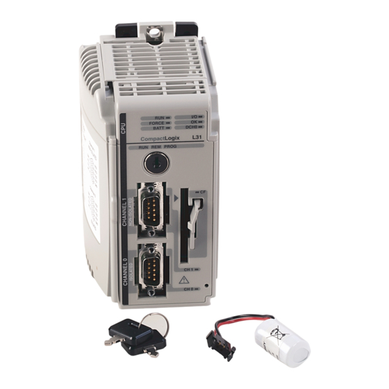
CompactLogix Controller
Catalog Numbers 1769-L32E, 1769-L35E
Topic
Important User Information
Environment and Enclosure
North American Hazardous Location Approval
European Hazardous Location Approval
About the Controller
Before You Begin
Connect the 1769-BA Battery
Install a 1784-CF64 or 1784-CF128 CompactFlash Card (optional)
Assemble the System
Mount the System
Make RS-232 Connections to the Controller
Make Ethernet Connections to the Controller
Load the Controller Firmware
Select the Controller's Operating Mode
Controller Status Indicators
RS-232 Serial Port Status Indicators (Channel 0)
CompactFlash Card Status Indicator
Module Status (MS) Indicator
Network Status (NS) Indicator
Link Status (LNK) Indicator
Specifications
Additional Resources
Installation Instructions
Page
2
3
4
5
5
6
7
8
9
11
15
18
25
29
31
33
33
33
34
35
36
40
Advertisement
Table of Contents

Related Manuals for Rockwell Automation Allen-Bradley CompactLogix 1769-L32E


Summary of Contents for Rockwell Automation Allen-Bradley CompactLogix 1769-L32E
- Page 1 Installation Instructions CompactLogix Controller Catalog Numbers 1769-L32E, 1769-L35E Topic Page Important User Information Environment and Enclosure North American Hazardous Location Approval European Hazardous Location Approval About the Controller Before You Begin Connect the 1769-BA Battery Install a 1784-CF64 or 1784-CF128 CompactFlash Card (optional) Assemble the System Mount the System Make RS-232 Connections to the Controller...
-
Page 2: Important User Information
In no event will Rockwell Automation, Inc. be responsible or liable for indirect or consequential damages resulting from the use or application of this equipment. -
Page 3: Environment And Enclosure
1769-L32E, 1769-L35E CompactLogix Controller Environment and Enclosure This equipment is intended for use in a Pollution Degree 2 industrial ATTENTION environment, in overvoltage Category II applications (as defined in IEC publication 60664-1), at altitudes up to 2000 meters (6562 ft) without derating. This equipment is considered Group 1, Class A industrial equipment according to IEC/CISPR Publication 11. -
Page 4: North American Hazardous Location Approval
4 1769-L32E, 1769-L35E CompactLogix Controller North American Hazardous Location Approval The following information applies when Informations sur l’utilisation de cet operating this equipment in hazardous équipement en environnements dangereux: locations: Products marked "CL I, DIV 2, GP A, B, C, D" are suitable for Les produits marqués "CL I, DIV 2, GP A, B, C, D"... -
Page 5: European Hazardous Location Approval
1769-L32E, 1769-L35E CompactLogix Controller European Hazardous Location Approval European Zone 2 Certification (The following applies when the product bears the Ex or EEx Marking) This equipment is intended for use in potentially explosive atmospheres as defined by European Union Directive 94/9/EC and has been found to comply with the Essential Health and Safety Requirements relating to the design and construction of Category 3 equipment intended for use in potentially explosive atmospheres, given in Annex II to this Directive. -
Page 6: Before You Begin
6 1769-L32E, 1769-L35E CompactLogix Controller Before You Begin Consider the following when planning your CompactLogix system: • The CompactLogix controller is always the leftmost module in the system. • The controller must be within four modules of the system power supply. -
Page 7: Connect The 1769-Ba Battery
1769-L32E, 1769-L35E CompactLogix Controller Connect the 1769-BA Battery The controller is shipped with the 1769-BA battery that is packed separately. To connect the battery, follow this procedure. The 1769-BA battery is the only battery you can use with the 1769-L32E and ATTENTION 1769-L35E controllers. - Page 8 8 1769-L32E, 1769-L35E CompactLogix Controller Battery 4. Slide the battery door back until it clicks into position. At the end of its life, the used battery should be collected separately from any unsorted municipal waste and recycled. Install a 1784-CF64 or 1784-CF128 CompactFlash Card (optional) Do not remove the CompactFlash card while the controller is reading from or ATTENTION writing to the card, as indicated by a flashing green CF status indicator.
-
Page 9: Assemble The System
1769-L32E, 1769-L35E CompactLogix Controller Follow these steps to install a CompactFlash card. 1. Push the locking tab to the right and insert the industrial CompactFlash card into the socket on the front of the controller. The label of the CompactFlash card faces toward the left. - Page 10 10 1769-L32E, 1769-L35E CompactLogix Controller Refer to the illustration when installing a controller. 44733 1. Disconnect line power. 2. Check that the lever of the adjacent module (A) is in the unlocked (fully right) position. 3. Use the upper and lower tongue-and-groove slots (B) to secure the modules together.
-
Page 11: Mount The System
1769-L32E, 1769-L35E CompactLogix Controller 7. Attach an end cap terminator (E) to the last module in the system by using the tongue-and-groove slots as before. 8. Lock the end cap bus terminator (F). Mount the System During panel or DIN rail mounting of all devices, be sure that all debris (such ATTENTION as metal chips or wire strands) is kept from falling into the controller. -
Page 12: System Dimensions
12 1769-L32E, 1769-L35E CompactLogix Controller System Dimensions 67.5 (2.68) (2.76) (1.38) 52.5 (2.06) (.58) (5.20) (4.65) 52.5 (1.38) (1.38) (2.06) (1.38) (1.38) 44734 Note: All dimensions are in mm (in.). Compact I/O expansion cables have the same dimensions as the end caps. Expansion cables can be used on either the right or left end. - Page 13 1769-L32E, 1769-L35E CompactLogix Controller Mount the Panel Mount the controller to a panel by using two screws per module. Use M4 or #8 panhead screws. Mounting screws are required on every module. This procedure lets you use the assembled modules as a template for drilling holes in the panel.
- Page 14 14 1769-L32E, 1769-L35E CompactLogix Controller Mount the Controller on the DIN Rail The controller can be mounted on the following DIN rails: • EN 50 022 - 35 x 7.5 mm (1.38 x 0.30 in.) • EN 50 022 - 35 x 15 mm (1.38 x 0.59 in.) This product is grounded through the DIN rail to chassis ground.
-
Page 15: Make Rs-232 Connections To The Controller
1769-L32E, 1769-L35E CompactLogix Controller Make RS-232 Connections to the Controller Connect the 9-pin female end of the serial cable to the serial port of the controller. 44735 If you connect or disconnect the serial cable with power applied to this module WARNING or the serial device on the other end of the cable, an electrical arc can occur. -
Page 16: Default Serial Configuration
16 1769-L32E, 1769-L35E CompactLogix Controller Default Serial Configuration Channel 0 (serial port) has the following default communication configuration. Parameter Default Protocol DF1 full-duplex Communication Rate 19.2 Kbps Parity None Station Address Control Lines No Handshaking Error Detection Embedded Responses Auto Detect Duplicate Packet (Message) Detect Enabled ACK Timeout... - Page 17 1769-L32E, 1769-L35E CompactLogix Controller Use the Channel 0 Default Communication Push Button The Channel 0 default communication push 44736 button is on the front of the controller in the lower right corner as shown in the illustration. Use the Channel 0 default communication push button to change from the user-defined communication configuration to the default communication mode.
-
Page 18: Make Ethernet Connections To The Controller
18 1769-L32E, 1769-L35E CompactLogix Controller Make Ethernet Connections to the Controller The 1769-L32E and 1769-L35E controllers ship with the BOOTP utility enabled. You must assign an IP address to the Ethernet port for the controller to communicate over an EtherNet/IP network. If you connect or disconnect the communications cable with power applied to WARNING this module or any device on the network, an electrical arc can occur. - Page 19 1769-L32E, 1769-L35E CompactLogix Controller Assign an IP Address You can set the IP address by using any of these utilities: • Rockwell BOOTP Utility (available with RSLinx and RSLogix 5000 software) • RSLinx software • RSLogix 5000 software Use BOOTP to Set the IP Address The BOOTP utility is a standalone program in one of the following directories: •...
- Page 20 20 1769-L32E, 1769-L35E CompactLogix Controller 4. Click OK. In the BOOTP Request History dialog, you see the hardware addresses of devices issuing BOOTP requests. 5. Double-click the hardware address of the device you want to configure. The hardware address is on the sticker on the left-side circuit board of the controller next to the battery.
- Page 21 1769-L32E, 1769-L35E CompactLogix Controller The New Entry dialog displays the device’s Ethernet Address (MAC). 6. Enter the IP address. 7. Click OK. 8. To permanently assign this configuration to the device, highlight the device and click Disable BOOTP/DHCP. When power is recycled, the device uses the configuration you assigned and does not issue a BOOTP request.
- Page 22 22 1769-L32E, 1769-L35E CompactLogix Controller 4. Navigate to the Ethernet network via the Serial network. 5. Right-click the Ethernet port (not the controller) and select Module Configuration 6. Select the Port Configuration tab. Publication 1769-IN020D-EN-P - October 2008...
- Page 23 1769-L32E, 1769-L35E CompactLogix Controller 7. Click the appropriate radio button to choose the Network Configuration type. 8. Enter the IP address, network (subnet) mask, and gateway address (if needed). Use RSLogix 5000 Software to Set the IP Address You can use RSLogix software to set the IP address. 1.
- Page 24 24 1769-L32E, 1769-L35E CompactLogix Controller 4. In the Controller Organizer, select properties for the Ethernet port. 5. Choose the Port Configuration tab. 6. Specify the IP address. 7. Click Apply. 8. Click OK. This sets the IP address in the hardware. This IP address should be the same IP address you assigned under the General tab.
-
Page 25: Load The Controller Firmware
1769-L32E, 1769-L35E CompactLogix Controller Install the Appropriate EDS Files If you have RSLinx software, version 2.42 or later, the most current EDS files were installed with the software. If you are using an earlier version of RSLinx software, you might need to install EDS files. You need EDS files for these devices: •... - Page 26 26 1769-L32E, 1769-L35E CompactLogix Controller Follow these steps to download firmware from the support website. 1. On the Rockwell Automation Support Page, click Software Updates, Firmware and Other Downloads under the Other Tools heading. 2. Click Firmware Updates. 3. Select the appropriate firmware update.
- Page 27 1769-L32E, 1769-L35E CompactLogix Controller 9. To start the update of the controller, click Finish and then click Yes. After the controller is updated, the status dialog displays Update complete. 10. Click OK. 11. To close the ControlFlash utility, click Cancel and then click Yes. Use AutoFlash to Load Firmware You can use AutoFlash to load firmware through a network connection.
- Page 28 28 1769-L32E, 1769-L35E CompactLogix Controller 5. Click Update Firmware. 6. Use the checkbox and pull-down to select your controller and firmware revision. 7. Click Update. 8. Click Yes. The firmware upgrade begins. DO NOT INTERRUPT THE FIRMWARE UPGRADE ONCE IT HAS BEGUN. IMPORTANT Interrupting the firmware upgrade may result in an inoperable controller.
-
Page 29: Select The Controller's Operating Mode
1769-L32E, 1769-L35E CompactLogix Controller 3. Remove the card and insert it into a controller that will use the same firmware and controller user program. When you apply power to the second controller, the image stored on the CompactFlash card is loaded into the controller. Select the Controller’s Operating Mode Use the keyswitch on the front panel of the controller to determine the controller’s operating mode. - Page 30 30 1769-L32E, 1769-L35E CompactLogix Controller Keyswitch Description Position • Upload/download projects. • Change between Remote Program, Remote Test, and Remote Run modes through the programming software. • Remote Run The controller executes (scans) tasks. • Enable outputs. • Edit online. •...
-
Page 31: Controller Status Indicators
1769-L32E, 1769-L35E CompactLogix Controller Controller Status Indicators Indicator Status Description The controller is in Program or Test mode. Solid green The controller is in Run mode. • FORCE No tags contain I/O force values. • I/O forces are inactive (disabled). •... - Page 32 32 1769-L32E, 1769-L35E CompactLogix Controller Indicator Status Description No power is applied. Flashing red If the controller is new, the controller requires a firmware update. If the controller is not new, a major fault occurred. To clear the fault, do one of the following: •...
-
Page 33: Compactflash Card Status Indicator
1769-L32E, 1769-L35E CompactLogix Controller RS-232 Serial Port Status Indicators (Channel 0) Indicator Status Description DCH0 Channel 0 is configured differently than the default serial configuration. Solid green Channel 0 has the default serial configuration. No RS-232 activity. Flashing green RS-232 activity. CompactFlash Card Status Indicator Do not remove the CompactFlash card while the controller is reading from or ATTENTION... -
Page 34: Network Status (Ns) Indicator
34 1769-L32E, 1769-L35E CompactLogix Controller Condition Status Description Solid red Held in reset The controller is holding the port in reset or the controller is faulted. Clear the controller fault. If the fault will not clear, replace the controller. Self-test The controller is performing its power-up self-test. -
Page 35: Link Status (Lnk) Indicator
1769-L32E, 1769-L35E CompactLogix Controller Condition Status Description Flashing Self-test The controller is performing its power-up self-test. red/green Normal operation, No action required. Link Status (LNK) Indicator Condition Status Description No link The port is not connected to a powered Ethernet device. -
Page 36: Specifications
36 1769-L32E, 1769-L35E CompactLogix Controller Specifications 1769-L32E, 1769-L35E - Technical Specifications Attribute 1769-L32E 1769-L35E Communication ports Channel 0 Isolated RS-232 38.4 Kbaud max EtherNet/IP 10/100 BASE-T User memory 750 KB 1.5 MB Nonvolatile memory 1784-CF64 or 1784-CF128 CompactFlash card Number of I/O modules, 16 I/O modules 30 I/O modules Number of I/O banks, max... - Page 37 1769-L32E, 1769-L35E CompactLogix Controller 1769-L32E, 1769-L35E - Technical Specifications Attribute 1769-L32E 1769-L35E Panel mounting screw 1.1…1.8 N•m (10...16 in•lb) torque (using M4 or #8 screws) Enclosure type rating None (open style) Wiring category 2 on communication ports Wire type Ethernet connections: RJ-45 connector according to IEC 60603-7, 2 or 4 pair Category 5e minimum cable according to TIA 568-B.1 or Category 5 cable according to ISO/IEC 24702...
- Page 38 38 1769-L32E, 1769-L35E CompactLogix Controller 1769-L32E, 1769-L35E - Environmental Specifications Attribute 1769-L32E 1769-L35E Relative humidity 5...95% noncondensing IEC 60068-2-30 (Test Db, Unpackaged Damp Heat) Vibration 5 g @ 10...500 Hz IEC 60068-2-6 (Test Fc, Operating) Operating shock DIN rail mount: 20 g; Panel mount: 30 g IEC 60068-2-27 (Test Ea, Unpackaged Shock) Nonoperating shock...
- Page 39 1769-L32E, 1769-L35E CompactLogix Controller 1769-L32E, 1769-L35E - Certifications Value Certifications c-UL-us UL Listed Industrial Control Equipment, certified for US and Canada. See UL File E65584. c-UL-us UL Listed for Class 1, Division 2 Group A,B,C,D Hazardous Locations, certified for U.S. and Canada. See UL File E194810.
-
Page 40: Additional Resources
TechConnect are trademarks of Rockwell Automation, Inc. Trademarks not belonging to Rockwell Automation are property of their respective companies. Publication 1769-IN020D-EN-P - October 2008 PN 33150 Supersedes Publication 1769-IN020C-EN-P - July 2007 Copyright © 2008 Rockwell Automation, Inc. All rights reserved. Printed in the U.S.A.
Need help?
Do you have a question about the Allen-Bradley CompactLogix 1769-L32E and is the answer not in the manual?
Questions and answers