
Related Manuals for Rockwell Automation Allen-Bradley MicroLogix


Summary of Contents for Rockwell Automation Allen-Bradley MicroLogix
- Page 1 Reference Manual Original Instructions MicroLogix Controllers to Micro800 Controllers Migration Guide Catalog Numbers Bulletin 1761, Bulletin 1762, Bulletin 1763, and Bulletin 2080...
- Page 2 If this equipment is used in a manner not specified by the manufacturer, the protection provided by the equipment may be impaired. In no event will Rockwell Automation, Inc. be responsible or liable for indirect or consequential damages resulting from the use or application of this equipment.
-
Page 3: Table Of Contents
Move and Logical ..........146 Rockwell Automation Publication 2080-RM002B-EN-E - June 2019... - Page 4 (Manual Conversion)......... 190 Rockwell Automation Publication 2080-RM002B-EN-E - June 2019...
-
Page 5: About This Publication
• MicroLogix to Micro800 Converter tool The MicroLogix to Micro800 Converter tool converts an RSLogix 500/ RSLogix Micro project into a Connected Components Workbench project. It provides conversion for ladder diagram (LD) programming languages in the MicroLogix processor. Rockwell Automation Publication 2080-RM002B-EN-E - June 2019... -
Page 6: Summary Of Changes
Description of features, installation, wiring, and publication 2080-UM003 specifications for the Micro800 expansion modules. Micro800 Plug-in Modules User Manual, Description of features, installation, wiring, and publication 2080-UM004 specifications for the Micro800 plug-in modules. Rockwell Automation Publication 2080-RM002B-EN-E - June 2019... - Page 7 Provides declarations of conformity, certificates, and other www.rockwellautomation.com/global/certification/ certification details. overview.page You can view or download publications at https://www.rockwellautomation.com/global/literature-library/overview.page. To order paper copies of technical documentation, contact your local Allen-Bradley distributor or Rockwell Automation sales representative. Rockwell Automation Publication 2080-RM002B-EN-E - June 2019...
- Page 8 Preface Notes: Rockwell Automation Publication 2080-RM002B-EN-E - June 2019...
- Page 9 HSC operation modes. HSC is supported on all Micro830, Micro850, and Micro870 controller catalogs, except on 2080-LCxx-xxAWB. PTO is only supported on Micro830, Micro850, and Micro870 controller catalog numbers that end in BB or VB. Rockwell Automation Publication 2080-RM002B-EN-E - June 2019...
-
Page 10: Controller Dimensions
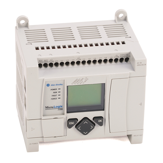
120 mm (4.72 in.) 1761-L16NWA 1761-L20AWA-5A 200 mm (7.87 in.) 1761-L20BWA-5A 1761-L32AWA 1761-L32BWA 1761-L32AAA 1761-L10BWB 120 mm (4.72 in.) 40 mm (1.57 in.) 1761-L10BXB 1761-L16BBB 1761-L16BWB 1761-L16NWB 1761-L20BWB-5A 200 mm (7.87 in.) 1761-L32BBB 1761-L32BWB Rockwell Automation Publication 2080-RM002B-EN-E - June 2019... - Page 11 Micro800 Controller Overview Chapter 1 MicroLogix 1100 Controller Dimensions Catalog Number 1763-L16AWA 110 mm (4.33 in.) 87 mm (3.43 in.) 90 mm (3.54 in.) 1763-L16BWA 1763-L16BBB 1763-L16DWD Rockwell Automation Publication 2080-RM002B-EN-E - June 2019...
- Page 12 MicroLogix 1200 Controller Dimensions Catalog Number 1762-L24AWA 110 mm (4.33 in.) 87 mm (3.43 in.) 90 mm (3.54 in.) 1762-L24AWAR 1762-L24BWA 1762-L24BWAR 1762-L24BXB 1762-L24BXBR 1762-L40AWA 160 mm (6.30 in.) 1762-L40AWAR 1762-L40BWA 1762-L40BWAR 1762-L40BXB 1762-L40BXBR Rockwell Automation Publication 2080-RM002B-EN-E - June 2019...
- Page 13 Micro800 Controller Overview Chapter 1 Micro820 Controller Dimensions Catalog Number 2080-LC20-20AWB 104 mm (4.09 in.) 75 mm (2.95 in.) 90 mm (3.54 in.) 2080-LC20-20AWBR 2080-LC20-20QWB 2080-LC20-20QWBR 2080-LC20-20QBB 2080-LC20-20QBBR Rockwell Automation Publication 2080-RM002B-EN-E - June 2019...
- Page 14 Catalog Number 2080-LC30-10QWB 100 mm (3.94 in.) 80 mm (3.15 in.) 90 mm (3.54 in.) 2080-LC30-10QVB 2080-LC30-16AWB 2080-LC30-16QWB 2080-LC30-16QVB 2080-LC30-24QWB 150 mm (5.91 in.) 2080-LC30-24QVB 2080-LC30-24QBB 2080-LC30-48AWB 210 mm (8.27 in.) 2080-LC30-48QWB 2080-LC30-48QVB 2080-LC30-48QBB Rockwell Automation Publication 2080-RM002B-EN-E - June 2019...
- Page 15 Micro800 Controller Overview Chapter 1 Micro850 Controller Dimensions Catalog Number 2080-LC50-24AWB 158 mm (6.22 in.) 80 mm (3.15 in.) 90 mm (3.54 in.) 2080-LC50-24QWB 2080-LC50-24QVB 2080-LC50-24QBB 2080-LC50-48AWB 283 mm (9.37 in.) 2080-LC50-48QWB 2080-LC50-48QVB 2080-LC50-48QBB Rockwell Automation Publication 2080-RM002B-EN-E - June 2019...
- Page 16 Chapter 1 Micro800 Controller Overview Micro870 Controller Dimensions Catalog Number 2080-LC70-24AWB 157 mm (6.22 in.) 80 mm (3.15 in.) 90 mm (3.54 in.) 2080-LC70-24QWB 2080-LC70-24QWBK 2080-LC70-24QBB 2080-LC70-24QBBK Rockwell Automation Publication 2080-RM002B-EN-E - June 2019...
-
Page 17: Feature And Specification Comparison
Operating Power 120/240V AC Power supply module – 2080-PSAC-12W Power supply module – 2080-PS120-240VAC 24V DC Communication RS-232 port 8-pin mini DIN Embedded RS-232/RS-485 serial port 8-pin min DIN RS-232/RS-485 serial port combo combo Rockwell Automation Publication 2080-RM002B-EN-E - June 2019... - Page 18 2 @ 100 kHz – 24-point controllers (not supported on relay output 3 @ 100 kHz – 48-point controllers controllers) (not supported on relay output controllers) Real-time clock Embedded Embedded Plug-in module – 2080-MEMBAK-RTC, 2080-MEMBAK-RTC2 Rockwell Automation Publication 2080-RM002B-EN-E - June 2019...
- Page 19 Embedded digital I/O, max Embedded analog I/O None Expansion modules supported Up to six expansion modules Up to four expansion modules Up to eight expansion modules Thermocouple/RTD Expansion module – 1762-IT4, 1762-IR4 Expansion module – 2085-IRT4 Rockwell Automation Publication 2080-RM002B-EN-E - June 2019...
- Page 20 (2) Requires Connected Components Workbench Developer Edition software version 12 or later, and Micro800 controller firmware revision 12 or later. (3) We recommend using the Allen-Bradley 2080-SD-2GB microSD card. The 2080-SDMEMRTC-SC plug-in module is an Encompass partner product. Rockwell Automation Publication 2080-RM002B-EN-E - June 2019...
-
Page 21: Generate Hardware Configuration
Generate Hardware following: Configuration 1. Launch Integrated Architecture Builder software from Start -> Programs -> Rockwell Automation -> Integrated Architecture Builder -> Integrated Architecture Builder. Alternatively, you can double-click the IAB icon on your computer. 2. Under Create, click New Project. - Page 22 Migration Wizard’ , and click OK. 4. Click Add Chassis to add your MicroLogix configuration. 5. Select the Migration Type based on your MicroLogix controller series. 6. Select your MicroLogix controller catalog number. Rockwell Automation Publication 2080-RM002B-EN-E - June 2019...
- Page 23 If the configuration exceeds the limit of the target controller, the wizard prompts you to change the target controller. 8. Select the options that apply to your MicroLogix application. 9. When the configuration is complete, click OK. 10. Click Generate Hardware. Rockwell Automation Publication 2080-RM002B-EN-E - June 2019...
- Page 24 Chapter 2 Plan Hardware Migration with Integrated Architecture Builder 11. Once the hardware is generated, you can view your configuration in the Hardware tab. 12. Click the Save icon to save your project. Rockwell Automation Publication 2080-RM002B-EN-E - June 2019...
-
Page 25: Migrate From A Micrologix 1000 Controller
1761-L16BWB 2080-LC20-20QWBR 1761-L16NWB 1761-L32BWB — — 1761-L10BWA 2080-LC20-20QWB, 2080-PSAC-12W x 1 1761-L16BWA 2080-LC20-20QWBR 1761-L16NWA 1761-L16AWA — — 1761-L32AAA 1761-L32AWA 1761-L32BWA 1761-L10BXB 2080-LC20-20QWB, 2080-OB4 x 1 1761-L16BBB 2080-LC20-20QWBR 1761-L20BWA-5A — — 1761-L20AWA-5A 1761-L20BWB-5A 1761-L32BBB Rockwell Automation Publication 2080-RM002B-EN-E - June 2019... - Page 26 1761-L10BXB 2080-LC30-10QWB 2080-OB4 x 1 1761-L16BBB 2080-LC30-16QWB 1761-L20BWA-5A 2080-LC30-24QWB 2080-PS120-240VAC x 1 2080-IF4 x 1 1761-L20AWA-5A 2080-LC30-48AWB 2080-OF2 x 1 1761-L20BWB-5A 2080-LC30-24QWB 2080-IF4 x 1 2080-OF2 x 1 1761-L32BBB 2080-LC30-48QBB 2080-OW4I x 1 Rockwell Automation Publication 2080-RM002B-EN-E - June 2019...
-
Page 27: Migrate From A Micrologix 1100 Controller
Plug-in Modules / Accessories 1763-L16AWA 2080-LC20-20AWB • Use 2080-PSAC-12W 2080-LC20-20AWBR • Input 00…03 can be used as analog or digital input simultaneously • Use 2080-IF2 if you require more than eight digital inputs Rockwell Automation Publication 2080-RM002B-EN-E - June 2019... - Page 28 • No RTC, use 2080-MEMBAK-RTC if you require RTC • No datalog, use 2080-SDMEM-RTC- SC if you require data logging (third- party plug-in module from Encompass Partner) • Requires 2085-ECR end cap at the end of expansion modules Rockwell Automation Publication 2080-RM002B-EN-E - June 2019...
-
Page 29: Migrate From A Micrologix 1200 Controller
• There is no combination output, use 1762-L24BXBR 2080-OW4I or 2085-OW8 if your require relay output 1762-L40BXB 2080-LC50-48QBB • No RTC, use 2080-MEMBAK-RTC if 1762-L40BXBR you require RTC • Requires 2085-ECR end cap at the end of expansion modules Rockwell Automation Publication 2080-RM002B-EN-E - June 2019... -
Page 30: Wiring Configuration
Wiring Configuration • MicroLogix 1000 Controller Wiring • MicroLogix 1100 Controller Wiring • MicroLogix 1200 Controller Wiring • Micro820 Controller Wiring • Micro830 Controller Wiring • Micro850 Controller Wiring • Micro870 Controller Wiring Rockwell Automation Publication 2080-RM002B-EN-E - June 2019... - Page 31 14...30V DC VDC + VDC (+) USED USED DC IN + 24V - VDC 1 VAC 1 VDC 2 VDC 3 VDC 4 VDC 4 VAC 1 VDC 2 VDC 3 VDC 1 Rockwell Automation Publication 2080-RM002B-EN-E - June 2019...
- Page 32 20 ms (1) Input circuits may be operated AC or DC on a group basis only. (2) Turn On and Turn Off Times are not adjustable. (3) All AC specifications are sinusoidal RMS values. Rockwell Automation Publication 2080-RM002B-EN-E - June 2019...
- Page 33 + 24V - USED USED USED DC OUT 85...264 VAC USED USED L2/N USED VAC 1 VAC 2 VDC 1 VDC 2 VDC 3 VAC 2 VDC 1 VDC 2 VDC 3 VAC 1 Rockwell Automation Publication 2080-RM002B-EN-E - June 2019...
- Page 34 VAC 1 1761-L16AWA 79...132V AC 79...132V AC L2/N USED USED 85...264 VAC L2/N VAC 2 VDC 1 VDC 2 VDC 3 VAC 2 VDC 1 VDC 2 VDC 3 VAC 1 VAC 1 Rockwell Automation Publication 2080-RM002B-EN-E - June 2019...
- Page 35 I/14 I/15 I/16 I/17 I/18 I/19 USED USED 85…264V AC L2/N O/10 O/11 VAC 2 VDC 1 VDC 2 VDC 3 VAC 2 VDC 1 VDC 2 VDC 3 VAC 1 VAC 1 Rockwell Automation Publication 2080-RM002B-EN-E - June 2019...
- Page 36 VAC 2 VDC 1 VDC 2 VDC 3 VAC 1 VAC 1 1761-L10BXB 14...30V DC 14...30V DC USED USED USED USED USED USED DC IN + 24V – 24V+ USED USED 24V– USED Rockwell Automation Publication 2080-RM002B-EN-E - June 2019...
- Page 37 I (+) (–) DC OUT 85…264V AC OA/0 OA/0 L2/N USED V (+) I (+) (–) Analog Channels VAC 2 VDC 1 VDC 2 VAC 2 VDC 1 VDC 2 VAC 1 VAC 1 Rockwell Automation Publication 2080-RM002B-EN-E - June 2019...
- Page 38 I (+) I (+) (–) 85...264V AC OA/0 OA/0 L2/N USED V (+) I (+) (–) Analog Channels VAC 2 VDC 1 VDC 2 VAC 2 VDC 1 VDC 2 VAC 1 VAC 1 Rockwell Automation Publication 2080-RM002B-EN-E - June 2019...
- Page 39 VDC 1 VDC 1 MicroLogix 1100 Controller Wiring 1763-L16AWA Inputs USED USED IV1(+) IV2(+) “NOT USED” terminals are not intended for use as connection points. +DCa -DCa Outputs L2/N 100-240 VAC USED USED Rockwell Automation Publication 2080-RM002B-EN-E - June 2019...
- Page 40 Sinking Inputs USED USED IV1(+) IV2(+) -DCa -DCb +DCa +DCb Sourcing Inputs USED USED IV1(+) IV2(+) +DCa -DCa +DCb -DCb +DCc -DCc Outputs + 24V - DC IN USED USED USED 24V+ 24V- USED Rockwell Automation Publication 2080-RM002B-EN-E - June 2019...
- Page 41 Migration Considerations Chapter 3 1763-L16DWD +DCa +DCb -DCa -DCb Sinking Inputs USED USED IV1(+) IV2(+) -DCa -DCb +DCa +DCb Sourcing Inputs USED USED IV1(+) IV2(+) +DCa -DCa Outputs 12/24V DC IN USED USED Rockwell Automation Publication 2080-RM002B-EN-E - June 2019...
- Page 42 OUT 0 OUT 1 OUT 2 OUT 5 OUT 6 OUT 8 NEUT DC 3 Outputs OUT 3 OUT 4 OUT 7 OUT 9 DC 0 DC 1 DC 2 DC 4 +DCa Rockwell Automation Publication 2080-RM002B-EN-E - June 2019...
- Page 43 IN 4 IN 6 IN 9 IN 11 IN 13 IN 15 IN 17 IN 19 IN 21 IN 23 NEUT DC 3 DC 5 Outputs DC 4 DC 2 DC 0 DC 1 Rockwell Automation Publication 2080-RM002B-EN-E - June 2019...
- Page 44 OUT 0 OUT 1 OUT 2 OUT 5 OUT 6 OUT 8 NEUT DC 3 Outputs OUT 3 OUT 4 OUT 7 OUT 9 DC 0 DC 1 DC 2 DC 4 +DCa Rockwell Automation Publication 2080-RM002B-EN-E - June 2019...
- Page 45 IN 9 IN 11 IN 13 IN 15 IN 17 IN 19 IN 21 IN 23 -DCa -DCb -DCc +DCa +DCc NEUT DC 3 DC 5 Outputs DC 4 DC 0 DC 1 DC 2 Rockwell Automation Publication 2080-RM002B-EN-E - June 2019...
- Page 46 IN 1 IN 3 IN 4 IN 6 IN 8 IN 10 IN 12 COM0 USED -DCb +DCa -DCa -DCa -DCb -DCc DC 3 NEUT Outputs DC 0 DC 1 +DCa +DCb +DCc -DCc Rockwell Automation Publication 2080-RM002B-EN-E - June 2019...
- Page 47 IN 19 IN 21 IN 23 USED -DCc -DCa +DCa -DCb +DCc -DCc -DCa -DCb -DCd +DCe -DCe NEUT DC 4 Outputs DC 0 DC 1 -DCe -DCd -DCc +DCa +DCb +DCd +DCc Rockwell Automation Publication 2080-RM002B-EN-E - June 2019...
- Page 48 I-10 I-06 +DC24 -DC24 O-00 O-01 O-02 O-05 +24 VDC -DC24 VO-0 O-03 O-04 O-06 -24 VDC +DC b L1 b L1 c +DC c -DC b L2 c L2 b -DC c Rockwell Automation Publication 2080-RM002B-EN-E - June 2019...
- Page 49 I-10 I-06 +DC24 -DC24 O-00 O-01 O-02 O-05 +24 VDC -DC24 VO-0 O-03 O-04 O-06 -24 VDC +DC c -DC c L1 a +DC e +DC d -DC d L2 a -DC e Rockwell Automation Publication 2080-RM002B-EN-E - June 2019...
- Page 50 I-01 I-03 I-04 I-08 I-10 I-06 +DC24 -DC24 O-00 O-02 -CM0 O-04 O-06 +24 VDC -DC24 VO-0 +CM0 O-01 O-03 +CM1 O-05 -CM1 -24 VDC +DC d +DC c -DC c -DC d Rockwell Automation Publication 2080-RM002B-EN-E - June 2019...
- Page 51 O-05 +DC c L1 a L1 b +DC d indicates high-speed inputs and outputs -DC c -DC d L2 a L2 b IMPORTANT Do not connect –DC24 (Output terminal 2) to Earth/Chassis Ground. Rockwell Automation Publication 2080-RM002B-EN-E - June 2019...
- Page 52 -DC e L2 b L2 c -DC f -DC g -DC h +DC i L2 a -DC i -DC j -DC k IMPORTANT Do not connect –DC24 (Output terminal 2) to Earth/Chassis Ground. Rockwell Automation Publication 2080-RM002B-EN-E - June 2019...
- Page 53 -DC b -DC c -DC d -DC e +DC f L2 e -DC f -DC g L2 g 2080-LC30-48AWB has no high-speed inputs. IMPORTANT Do not connect –DC24 (Output terminal 2) to Earth/Chassis Ground. Rockwell Automation Publication 2080-RM002B-EN-E - June 2019...
- Page 54 O-02 O-04 O-07 O-09 -24 VDC +DC c L1 b L1 c +DC c L2 b -DC c L2 c -DC c IMPORTANT Do not connect –DC24 (Output terminal 2) to Earth/Chassis Ground. Rockwell Automation Publication 2080-RM002B-EN-E - June 2019...
- Page 55 O-07 O-09 +24 VDC -DC24 O-00 -CM0 O-02 O-04 O-06 O-08 -CM1 -24 VDC +DC d +DC e -DC d -DC e IMPORTANT Do not connect –DC24 (Output terminal 2) to Earth/Chassis Ground. Rockwell Automation Publication 2080-RM002B-EN-E - June 2019...
- Page 56 1601-XLP60EQ power supply instead of a 2080-PS120-240VAC power supply. Make sure to wire both the Micro870 controller and 2085-EP24VDC expansion power supply to the same 1601-XLP60EQ power supply. Rockwell Automation Publication 2080-RM002B-EN-E - June 2019...
- Page 57 1601-XLP60EQ power supply instead of a 2080-PS120-240VAC power supply. Make sure to wire both the Micro870 controller and 2085-EP24VDC expansion power supply to the same 1601-XLP60EQ power supply. Rockwell Automation Publication 2080-RM002B-EN-E - June 2019...
- Page 58 1601-XLP60EQ power supply instead of a 2080-PS120-240VAC power supply. Make sure to wire both the Micro870 controller and 2085-EP24VDC expansion power supply to the same 1601-XLP60EQ power supply. Rockwell Automation Publication 2080-RM002B-EN-E - June 2019...
-
Page 59: Overview
(UDF) or User Defined Function Block (UDFB). A UDF is similar to a traditional subroutine and uses less memory than a UDFB, while a UDFB can have multiple instances. Although a UDFB can be executed within another Rockwell Automation Publication 2080-RM002B-EN-E - June 2019... - Page 60 When a cycle time is not specified, a resource performs all steps in the loop then restarts a new cycle without waiting. For more information, see the chapter, “Program Execution in Micro800 Controllers” in the Micro830, Micro850, and Micro870 Programmable Controllers User Manual, publication 2080-UM002. Rockwell Automation Publication 2080-RM002B-EN-E - June 2019...
- Page 61 The Logix theme can be selected from the navigation bar. When you change to the Logix theme, all your ladder diagram instructions names are updated to how they were named in the RSLogix 500/RSLogix Micro software. Rockwell Automation Publication 2080-RM002B-EN-E - June 2019...
- Page 62 MicroLogix to Micro800 Converter tool does not handle it. You have to identify and configure interrupts manually. For an example of how to configure an interrupt, see Configure Interrupts on a Micro800 Controller on page 179. Rockwell Automation Publication 2080-RM002B-EN-E - June 2019...
- Page 63 Components Workbench software, some feature or parameter does not match. You must verify the logic and make necessary changes. For example, when you paste a PID instruction from RSLogix 500/RSLogix Micro software to Connected Components Workbench software, the instruction is not identical. Rockwell Automation Publication 2080-RM002B-EN-E - June 2019...
- Page 64 TOF instruction in RSLogix 500/ RSLogix Micro software The instruction is configured with a two second delay. TOF instruction in The unknown instruction ‘0’ is Connected Components Workbench software dropped out of the TOP instruction. Rockwell Automation Publication 2080-RM002B-EN-E - June 2019...
-
Page 65: What You Need
2. Save the opened project file as a .SLC file with the following settings: • Save as type = Library Files (*.SLC) • Export database = Selected • Export File types = Logix Rockwell Automation Publication 2080-RM002B-EN-E - June 2019... - Page 66 IMPORTANT The converter tool only supports MicroLogix controllers. The tool does not work with other controllers even if you convert their project files to .SLC files. For general information about the converter tool, see the MicroLogix to Micro800 Converter tool help. Rockwell Automation Publication 2080-RM002B-EN-E - June 2019...
- Page 67 4. Select Connected Components Workbench Standard Edition (select Developer Edition if you have a valid activation key), then select version 12.00.00. 5. Click Downloads. The Downloads page displays. 6. Click the Show Downloads icon. Rockwell Automation Publication 2080-RM002B-EN-E - June 2019...
- Page 68 Chapter 4 Convert a MicroLogix Project to a Micro800 Project The Available Downloads dialog displays. 7. Select the Connected Components Workbench software, then click Downloads. The Download Cart dialog displays. Rockwell Automation Publication 2080-RM002B-EN-E - June 2019...
- Page 69 There are two ways to run the MicroLogix to Micro800 Converter tool: • From the Connected Components Workbench menu, Select Tools -> MicroLogix Library Converter. The MicroLogix to Micro800 Converter tool dialog displays. Rockwell Automation Publication 2080-RM002B-EN-E - June 2019...
- Page 70 5. Click OK to generate the Connected Components Workbench project. Once the project is converted, you must make additional changes before it can be used. If you build the project immediately after conversion, there are many errors Rockwell Automation Publication 2080-RM002B-EN-E - June 2019...
- Page 71 I/O modules, to a 24-point Micro870 controller. Since only Micro870 controllers support more than four expansion I/O modules, you must assign the remaining MicroLogix embedded I/O points to the Micro870 expansion I/O modules. Rockwell Automation Publication 2080-RM002B-EN-E - June 2019...
- Page 72 UDFs and your program calls these functions in the main routine. However, if any of the subroutines is initiated by an interrupt, you must convert the interrupt routine manually. See the Connected Components Workbench software help on Rockwell Automation Publication 2080-RM002B-EN-E - June 2019...
- Page 73 The Micro800 instructions function slightly differently, but they can easily be configured to achieve the same result as the MicroLogix instructions. Examples of similar instructions are ONS, OSF, OSR, counter, and timer. Rockwell Automation Publication 2080-RM002B-EN-E - June 2019...
- Page 74 Since a Micro800 controller has its own timer, you are expected to use this timer to develop your own PWM function within the block. Alternatively, an example of the Micro800 PWM UDFB code is available on the Rockwell Automation Sample Code Library at https:// www.rockwellautomation.com/global/sample-code/overview.page.
- Page 75 Function files The design of Micro800 controllers eliminates the use of function files, but configuration of functions is done through instructions or I/O configuration. Instructional behavior differences are described RLL Instruction Mapping on page Rockwell Automation Publication 2080-RM002B-EN-E - June 2019...
- Page 76 Micro800 controllers. Many of the INT arrays that are created by the converter tool are used in Micro800 instructions that require a REAL data type. Resolving data type errors typically reduces the number of errors significantly. Rockwell Automation Publication 2080-RM002B-EN-E - June 2019...
- Page 77 You can configure it to an interrupt from the controller configuration section or delete the interrupt program if the interrupt is not needed in the program. • For this project, the Interrupt3_USER_FAULT can be deleted when not in use. Rockwell Automation Publication 2080-RM002B-EN-E - June 2019...
- Page 78 Error list. Once no errors are encountered and all warnings have been addressed, save the project and test to see if it has the desired behavior. Rockwell Automation Publication 2080-RM002B-EN-E - June 2019...
-
Page 79: Convert Your Project Manually
Connected Project Report Components Workbench software. 1. Open the existing RSLogix 500/RSLogix Micro project. 2. Go to File −> Report Options. 3. Modify the report options as necessary. 4. Click Print. Rockwell Automation Publication 2080-RM002B-EN-E - June 2019... -
Page 80: Create Equivalent Program Files
UDF or UDFB to replace the subroutine. Create UDF or UDFB to Replace Subroutine 1. Right-click UDFB or UDF under project organizer and add a ladder diagram. 2. Rename the ladder diagram according to your subroutine. Rockwell Automation Publication 2080-RM002B-EN-E - June 2019... -
Page 81: Create Representative Data Files
• Binary (B3) • Integer (N7) Set Up Embedded I/O Variables 1. On the Project Organizer panel, double-click Global Variables. 2. Create an alias for the embedded I/O following the comments in RSLogix 500 software. Rockwell Automation Publication 2080-RM002B-EN-E - June 2019... - Page 82 Components Workbench software version 8 or later to support array of integer bit addressing. 1. On the Project Organizer panel, double-click Global Variables. 2. Enter the N7 and B3 variables as shown in the following example: Rockwell Automation Publication 2080-RM002B-EN-E - June 2019...
-
Page 83: Create Equivalent Logic In Program File
1. To paste code from an RSLogix 500/RSLogix Micro program, you must change Connected Components Workbench software to the Logix theme. This theme allows the ladder editor to understand the code that is being pasted. Rockwell Automation Publication 2080-RM002B-EN-E - June 2019... -
Page 84: Logix Examples
N7:10. In Connected Components Workbench software, we replace it with N7[10], which was created earlier. The following ladder program enables indexed addressing to be used in Connected Components Workbench software. Rockwell Automation Publication 2080-RM002B-EN-E - June 2019... - Page 85 On the Toolbox panel, drag Instruction Block into the blank rung and select MOV from the Instruction Block Selector window. Enter the following parameters: • i1 = Output_Value • i2 = Base_Address • o1= Offset_Address Rockwell Automation Publication 2080-RM002B-EN-E - June 2019...
- Page 86 Chapter 4 Convert a MicroLogix Project to a Micro800 Project Add a branch to the + instruction block. On the Toolbox panel, drag Branch and place it above the + (Addition) instruction block. Rockwell Automation Publication 2080-RM002B-EN-E - June 2019...
- Page 87 Assign a variable if you want to monitor the elapsed time. The rungs displays as follows: 2. Add a rung. This rung is used to add the Timer Done bit. Rockwell Automation Publication 2080-RM002B-EN-E - June 2019...
- Page 88 The PTO design for Micro800 controllers is the same as MicroLogix controllers, however the configuration, and programming is different. You can see article number 602158 on the Rockwell Automation Knowledgebase for guidance on how to setup and program PTO for your application.
- Page 89 Instruction Parameter Values Details ANY_TO_UDINT N7[0] Output Mask hsapp_0.OutputMask ANY_TO_UDINT N7[1] High Preset Output hsapp_0.HPOutput ANY_TO_DINT N7[2] High Preset Setting hsapp_0.HPSetting ANY_TO_UDINT N7[3] Low Preset Output hsapp_0.LPOutput ANY_TO_DINT N7[4] Low Preset Setting hsapp_0.LPSetting Rockwell Automation Publication 2080-RM002B-EN-E - June 2019...
- Page 90 UFSetting are set before triggering Start/Run for the HSC. Otherwise, the controller is faulted. It is optional to set a value for LPSetting for certain counting modes. The following rung shows the data assignment to the required HSC parameters. Rockwell Automation Publication 2080-RM002B-EN-E - June 2019...
-
Page 91: Build And Test Your Project
1. Change controller to the simulator controller. a. Right-click the controller and select 'Change Controller…' b. Select the Micro850 simulator controller 2080-LC50-48QWB-SIM and click OK. Rockwell Automation Publication 2080-RM002B-EN-E - June 2019... - Page 92 2. Start and power on the simulator. a. Click the 'Start Micro800 Simulator' icon from the toolbar to launch the Micro800 Simulator. b. Click the ‘Synchronize’ icon from the toolbar to sync your I/O configuration with the simulator. Rockwell Automation Publication 2080-RM002B-EN-E - June 2019...
- Page 93 3. When the Micro800 Simulator is powered on, it appears in the FTLinx and RSLinx® software. You can download a project to the simulator as though it is a physical Micro800 controller. a. Right-click the controller and select Download. Rockwell Automation Publication 2080-RM002B-EN-E - June 2019...
- Page 94 Convert a MicroLogix Project to a Micro800 Project b. Select the Micro800 simulator in the RSLinx Connection Browser and click OK. 4. Test your application with Micro800 Simulator. a. Click an input terminal to turn on the corresponding digital input. Rockwell Automation Publication 2080-RM002B-EN-E - June 2019...
- Page 95 5. Click Device -> Exit to close the simulator. Test Project With a Physical Controller 1. Build the project by selecting Device -> Build from the menu. Rockwell Automation Publication 2080-RM002B-EN-E - June 2019...
- Page 96 The Output window displays. The build result should show zero errors. 2. Download the project to the controller by selecting Device -> Download from the menu bar. The Connection Browser window displays. 3. Select the controller and click OK. Rockwell Automation Publication 2080-RM002B-EN-E - June 2019...
- Page 97 Active rungs are displayed in red and inactive rungs in blue. You can monitor the live values in the program. The program goes into Debug mode for Connected Components Workbench software version 8 or later. Rockwell Automation Publication 2080-RM002B-EN-E - June 2019...
- Page 98 Chapter 4 Convert a MicroLogix Project to a Micro800 Project Notes: Rockwell Automation Publication 2080-RM002B-EN-E - June 2019...
-
Page 99: Overview
See the reference manual for more details. See the following table for definitions of terms used in this chapter. Definitions, Acronyms, and Abbreviations Term Definition Relay Ladder Logic Connected Components Workbench software Most Significant Bit Rockwell Automation Publication 2080-RM002B-EN-E - June 2019... -
Page 100: Bit Shift
NOT supported Output File The output is in the same file as input Provides the shifted output Output Indicates that the operation is over Not Supported Output Rung enable output Rung enable output Rockwell Automation Publication 2080-RM002B-EN-E - June 2019... - Page 101 Control • • Length • • Source • • • • • • • • • (1) Control file only. Not valid for Timers and Counters. (2) See Important note about indirect addressing. Rockwell Automation Publication 2080-RM002B-EN-E - June 2019...
- Page 102 When EN is TRUE, for 32-bit integers only, it performs a shift by NbS bits and places 0 in the MSB location. Input File Immediate value or files that contain value 32-bit variable to be shifted. Rockwell Automation Publication 2080-RM002B-EN-E - June 2019...
- Page 103 2. The number of bits in the bit array, up to 1680 bits. A length value of 0 causes the input bit to be transferred to the UL bit. 3. The shift operation clears the index register S:24 to zero. Rockwell Automation Publication 2080-RM002B-EN-E - June 2019...
- Page 104 IMPORTANT You cannot use indirect addressing with: S, MG, PD, RTC, HSC, PTOX, PWMX, STI, EII, BHI, MMI, CS, IOS, and DLS files. Supported Data Types in Micro800 Controllers Parameter Data Type • • • • • Rockwell Automation Publication 2080-RM002B-EN-E - June 2019...
-
Page 105: Communication
Function block Description MSG_CIPGENERIC Send a CIP generic explicit message. MSG_CIPSYMBOLIC Send a CIP symbolic explicit message. MSG_MODBUS Send a Modbus message. MSG_MODBUS2 Send a MODBUS/TCP message over an Ethernet Channel. Rockwell Automation Publication 2080-RM002B-EN-E - June 2019... -
Page 106: Comparison
(2) Only use the High-Speed Counter Accumulator (HSC.ACC) for Source A in GRT, LES, GEQ, and LEQ instructions. (3) See Important note about indirect addressing. IMPORTANT You cannot use indirect addressing with: S, MG, PD, RTC, HSC, PTOX, PWMX, STI, EII, BHI, MMI, CS, IOS, and DLS files. Rockwell Automation Publication 2080-RM002B-EN-E - June 2019... - Page 107 Rung enable output Rung enable output Connected Components Workbench Software Limitations Both the inputs must be of the same data type. Behavioral Differences None Supported Data Types in MicroLogix Controllers Comparison on page 106. Rockwell Automation Publication 2080-RM002B-EN-E - June 2019...
- Page 108 Source variable Output When the values are not equal, the rung goes TRUE if Source A and Source B are unequal true and the output is energized. Output Rung enable output Rung enable output Rockwell Automation Publication 2080-RM002B-EN-E - June 2019...
- Page 109 • • • • • • • • • • • • Description This instruction checks whether one value is less than another value. Functional Block Diagram RSLogix 500/RSLogix Micro Connected Components Workbench Rockwell Automation Publication 2080-RM002B-EN-E - June 2019...
- Page 110 • • • • • • • • • • • • • • • • • • • • • • • • • • • • • • • • • Rockwell Automation Publication 2080-RM002B-EN-E - June 2019...
- Page 111 Rung enable output Rung enable output Connected Components Workbench Software Limitations Both the inputs must be of the same data type. Behavioral Differences None Supported Data Types in MicroLogix Controllers Comparison on page 106. Rockwell Automation Publication 2080-RM002B-EN-E - June 2019...
- Page 112 TRUE if Source A is greater than Source B value in Source B, the rung goes true and the output is energized (provided no other forces affect the status of the rung). Output Rung enable output Rung enable output Rockwell Automation Publication 2080-RM002B-EN-E - June 2019...
- Page 113 • • • • • • • • • Description This instruction checks whether one value is greater than or equal to another value. Functional Block Diagram RSLogix 500/RSLogix Micro Connected Components Workbench Rockwell Automation Publication 2080-RM002B-EN-E - June 2019...
- Page 114 • • • • • • • • • • • • • • • • • • • • • • • • • • • • • • • • • Rockwell Automation Publication 2080-RM002B-EN-E - June 2019...
- Page 115 TRUE when the Test value is within or equal to limits Output TRUE if X is above High limit Output TRUE if X is out of limits Output TRUE if X is below Low limit Output Rung enable output Rung enable output Rockwell Automation Publication 2080-RM002B-EN-E - June 2019...
- Page 116 The output is FALSE when the Test value is within the The behavior of the output Q is shown according to the Upper and Lower limit, that is following graph: Upper Limit < Test value < Lower Limit. Otherwise the output is TRUE. Rockwell Automation Publication 2080-RM002B-EN-E - June 2019...
- Page 117 IMPORTANT You cannot use indirect addressing with: S, MG, PD, RTC, HSC, PTOX, PWMX, STI, EII, BHI, MMI, CS, IOS, and DLS files. Supported Data Types in Micro800 Controllers Parameter Data Type • • • • • • • • • Rockwell Automation Publication 2080-RM002B-EN-E - June 2019...
-
Page 118: Control
When the connection on the left of the Jump is FALSE, the next immediately following the JMP instruction. instruction after the jump is executed. Connected Components Workbench Software Limitations None Behavioral Differences None Supported Data Types in MicroLogix Controllers Not applicable Rockwell Automation Publication 2080-RM002B-EN-E - June 2019... - Page 119 It is always evaluated as true or logic 1. execution to this rung. Connected Components Workbench Software Limitations None Behavioral Differences None Supported Data Types in MicroLogix Controllers Not applicable Rockwell Automation Publication 2080-RM002B-EN-E - June 2019...
- Page 120 When the left side of the rung is FALSE, the instructions below it immediately following the RET instruction. continue to get executed. Connected Components Workbench Software Limitations None Behavioral Differences None Supported Data Types in MicroLogix Controllers Not applicable Rockwell Automation Publication 2080-RM002B-EN-E - June 2019...
- Page 121 3. The suspend file (program or subroutine number that identifies where the executed SUS instruction resides) is placed in word 8 (S:8) of the status file. Supported Data Types in MicroLogix Controllers Not applicable Rockwell Automation Publication 2080-RM002B-EN-E - June 2019...
- Page 122 I/O, and resumes scanning at rung 0 of the main program. No operation No operation Output If TRUE, the function is performed TND/ENO Same as TND Connected Components Workbench Software Limitations None Rockwell Automation Publication 2080-RM002B-EN-E - June 2019...
-
Page 123: I/O Related Interrupt
• • I/O Related Interrupt Description This instruction is used to update the input data without waiting for the next input scan to begin. Functional Block Diagram RSLogix 500/RSLogix Micro Connected Components Workbench Rockwell Automation Publication 2080-RM002B-EN-E - June 2019... - Page 124 Table 5 - IIM Instruction Valid Addressing Modes and File Types Parameter Data Files Function Files Address Address Level Mode Slot • • • • Mask • • • • • • • • • Length • Rockwell Automation Publication 2080-RM002B-EN-E - June 2019...
- Page 125 Output. The program scan then resumes. No operation No operation Input Slot Indicates the slot or a particular word in a slot. Output Slot Slot number Input Mask Immediate value or files that contain value Not supported Rockwell Automation Publication 2080-RM002B-EN-E - June 2019...
- Page 126 Slot • • • • Mask • • • • • • • • • Length • Supported Data Types for Micro800 Parameter Data Type EN/ENABLE • OutputType • OutputSlot • • • Rockwell Automation Publication 2080-RM002B-EN-E - June 2019...
-
Page 127: Selectable Timed Interrupts
Select the type Output Rung enable output UID/ENO Rung enable output IRQ Type Select the type Connected Components Workbench Software Limitations None Behavioral Differences None Supported Data Types in MicroLogix Controllers Not applicable Rockwell Automation Publication 2080-RM002B-EN-E - June 2019... - Page 128 This instruction has no effect on the operation of the STI timer or setpoint. Output Rung enable output UIE/ENO Rung enable output IRQ Type Select the type Connected Components Workbench Software Limitations None Rockwell Automation Publication 2080-RM002B-EN-E - June 2019...
- Page 129 None Supported Data Types in MicroLogix Controllers Not applicable Supported Data Types for Micro800 Parameter Data Type • IRQType • • Description Configure timer Functional Block Diagram RSLogix 500/RSLogix Micro Connected Components Workbench Rockwell Automation Publication 2080-RM002B-EN-E - June 2019...
- Page 130 The file number and setpoint is entered into the status file (S:31 and S:30). Supported Data Types in MicroLogix Controllers Not applicable Supported Data Types for Micro800 Parameter Data Type EN/ENABLE • IRQType • SetPoint • STIS • Rockwell Automation Publication 2080-RM002B-EN-E - June 2019...
-
Page 131: File Manipulation
Input Length Number of words to be copied from source to Length Number of elements to copy. destination Input Swap Swap the bytes Output Status Values Output Rung enable output Rung enable output Rockwell Automation Publication 2080-RM002B-EN-E - June 2019... - Page 132 • Length • (1) See Important note about indirect addressing. IMPORTANT You cannot use indirect addressing with: S, MG, PD, RTC, HSC, PTOX, PWMX, STI, EII, BHI, MMI, CS, IOS, and DLS files. Rockwell Automation Publication 2080-RM002B-EN-E - June 2019...
-
Page 133: Math
(2) The Data Log Status file can only be used for the following math instructions: ADD, SUB, MUL, DIV, NEG, and SCP. (3) See Important note about indirect addressing. IMPORTANT You cannot use indirect addressing with: S, MG, PD, RTC, HSC, PTOX, PWMX, STI, EII, BHI, MMI, CS, IOS, and DLS files. Rockwell Automation Publication 2080-RM002B-EN-E - June 2019... - Page 134 +32,767 (a number that requires more than 16 bits to represent), the processor sets S:0/1 (overflow bit) and S:5/0 (overflow trap bit, major error 0020). Bit S:5/0 in the program can be monitored. Rockwell Automation Publication 2080-RM002B-EN-E - June 2019...
- Page 135 • • • • • • • • • • • • • • • • • • • • • • • • • • • • • • • • • Rockwell Automation Publication 2080-RM002B-EN-E - June 2019...
- Page 136 +32,767 (a number that requires more than 16 bits to represent), the processor sets S:0/1 (overflow bit) and S:5/0 (overflow trap bit, major error 0020). Bit S:5/0 in the program can be monitored. Rockwell Automation Publication 2080-RM002B-EN-E - June 2019...
- Page 137 • • • • • • • • • • • • • • • • • • • • • • • • • • • • • • • • • Rockwell Automation Publication 2080-RM002B-EN-E - June 2019...
- Page 138 S:2/14 (math overflow selection bit) set, then the unsigned, truncated, least significant 16 bits of the overflow value remains in the destination. The math register contains the 32-bit signed integer result of the multiply operation. This result is valid at overflow. Rockwell Automation Publication 2080-RM002B-EN-E - June 2019...
- Page 139 • • • • • • • • • • • • • • • • • • Description Perform division on two numbers. Functional Block Diagram RSLogix 500/RSLogix Micro Connected Components Workbench Rockwell Automation Publication 2080-RM002B-EN-E - June 2019...
- Page 140 Sets if result is zero, otherwise resets; undefined if overflow is set. S:0/3 Sign (S) Sets if result is negative, otherwise resets; undefined if overflow is set. Supported Data Types in MicroLogix Controllers Math on page 133. Rockwell Automation Publication 2080-RM002B-EN-E - June 2019...
- Page 141 Input Source A 32-bit math register Source variable Input Source (or Immediate value or files that contain value (16 Source variable divisor) bits) Output Dest (or Contains the destination address Destination variable quotient) Rockwell Automation Publication 2080-RM002B-EN-E - June 2019...
- Page 142 • • • • • • • • • • • • • • • • • • • • • • • • • • • • • • • • • Rockwell Automation Publication 2080-RM002B-EN-E - June 2019...
- Page 143 The value 32,767 is placed in the destination. If S:2/14 (math overflow selection bit) is set, then the unsigned, truncated overflow remains in the destination. S:0/2 Zero (Z) Sets if result is zero, otherwise resets. S:0/3 Sign (S) Sets if result is negative, otherwise resets. Rockwell Automation Publication 2080-RM002B-EN-E - June 2019...
- Page 144 Files that contain value or immediate value Source variable. Must be greater than equal to zero Output Dest Contains the destination address SQRT Destination variable. The result is zero for negative input Output Rung enable output Rung enable output Rockwell Automation Publication 2080-RM002B-EN-E - June 2019...
- Page 145 • • • (1) See Important note about indirect addressing. IMPORTANT You cannot use indirect addressing with: S, MG, PD, RTC, HSC, PTOX, PWMX, STI, EII, BHI, MMI, CS, IOS, and DLS files. Rockwell Automation Publication 2080-RM002B-EN-E - June 2019...
-
Page 146: Move And Logical
• • • • • • • • • • • • • • • • • • • • • • • • • • • • • • • • • Rockwell Automation Publication 2080-RM002B-EN-E - June 2019... - Page 147 1. The bit field variable can also be moved to an integer file. For example, B3:0 can be added to N7:0 where all 16 bits in the B3:0 fields are used for moving. Rockwell Automation Publication 2080-RM002B-EN-E - June 2019...
- Page 148 • • • • • • • • • • • • • • • • • • • • • • • • • • • • • • • • • Rockwell Automation Publication 2080-RM002B-EN-E - June 2019...
- Page 149 Source variable (BOOL only) Output Dest Contains the destination address Destination variable (BOOL only) Output Rung enable output Rung enable output Connected Components Workbench Software Limitations The Connected Components Workbench AND operator only supports BOOL values. Rockwell Automation Publication 2080-RM002B-EN-E - June 2019...
- Page 150 Supported Data Types in Micro800 Controllers Parameter Data Type • • • • Description Perform logical XOR operation on two values bit by bit. Functional Block Diagram RSLogix 500/RSLogix Micro Connected Components Workbench Rockwell Automation Publication 2080-RM002B-EN-E - June 2019...
- Page 151 Sets if result is negative (most significant bit is set); otherwise resets. Supported Data Types in MicroLogix Controllers Move and Logical on page 146. Supported Data Types in Micro800 Controllers Parameter Data Type • • • • • Rockwell Automation Publication 2080-RM002B-EN-E - June 2019...
- Page 152 Source variable (BOOL only) Output Dest Contains the destination address Destination variable (BOOL only) Output Rung enable output Rung enable output Connected Components Workbench Software Limitations The Connected Components Workbench OR operator only supports BOOL values. Rockwell Automation Publication 2080-RM002B-EN-E - June 2019...
- Page 153 Supported Data Types in Micro800 Controllers Parameter Data Type • • • • • Description Perform logical NOT operation on two values bit by bit. Functional Block Diagram RSLogix 500/RSLogix Micro Connected Components Workbench Rockwell Automation Publication 2080-RM002B-EN-E - June 2019...
- Page 154 Sets if result is negative (most significant bit is set); otherwise resets. Supported Data Types in MicroLogix Controllers Move and Logical on page 146. Supported Data Types in Micro800 Controllers Parameter Data Type • • • • Rockwell Automation Publication 2080-RM002B-EN-E - June 2019...
-
Page 155: Relay Type
(1) PTOX and PWMX files are only for use with MicroLogix 1400 BXB or BXBA unit. (2) See Important note about indirect addressing. IMPORTANT You cannot use indirect addressing with: S, MG, PD, RTC, HSC, PTOX, PWMX, STI, EII, BHI, MMI, CS, IOS, and DLS files. Rockwell Automation Publication 2080-RM002B-EN-E - June 2019... - Page 156 (1) PTOX and PWMX files are only for use with MicroLogix 1400 BXB or BXBA unit. (2) See Important note about indirect addressing. IMPORTANT You cannot use indirect addressing with: S, MG, PD, RTC, HSC, PTOX, PWMX, STI, EII, BHI, MMI, CS, IOS, and DLS files. Rockwell Automation Publication 2080-RM002B-EN-E - June 2019...
- Page 157 • • • • • • • • • • (1) PTOX and PWMX files are only for use with MicroLogix 1400 BXB or BXBA unit. (2) See Important note about indirect addressing. Rockwell Automation Publication 2080-RM002B-EN-E - June 2019...
- Page 158 2. If an error condition occurs that halts processing, the physical output is turned off. But once the error condition is cleared the controller resumes operation with the OTL in the state that is determined by its data table value. Rockwell Automation Publication 2080-RM002B-EN-E - June 2019...
- Page 159 The bit must be set condition goes false. The bit must be set with a Set with an OTL instruction. Coil instruction. Connected Components Workbench Software Limitations None Rockwell Automation Publication 2080-RM002B-EN-E - June 2019...
- Page 160 IMPORTANT You cannot use indirect addressing with: S, MG, PD, RTC, HSC, PTOX, PWMX, STI, EII, BHI, MMI, CS, IOS, and DLS files. Description Trigger an event one at a time. Functional Block Diagram RSLogix 500/RSLogix Micro Connected Components Workbench One Shot Rising R_TRIG Rockwell Automation Publication 2080-RM002B-EN-E - June 2019...
- Page 161 Table 18 - OSR and OSF Instructions Valid Addressing Modes and File Types Parameter Data Files Function Files Address Address Level Mode Storage Bit • • • • Output Bit • • • • • • • • Rockwell Automation Publication 2080-RM002B-EN-E - June 2019...
-
Page 162: Timer And Counter
Table 20 - CTD and CTU Instructions Valid Addressing Modes and File Types Parameter Data Files Function Files Address Address Level Mode Counter • • • Preset • • Accumulator • • (1) Valid for Counter Files only. Rockwell Automation Publication 2080-RM002B-EN-E - June 2019... - Page 163 This bit is set when the Accum value is greater Not supported (Done) than or equal to the Preset value. Output Accum Count down value Count down value Output Rung enable output Rung enable output Rockwell Automation Publication 2080-RM002B-EN-E - June 2019...
- Page 164 Components Workbench, the underflow bit is SET when the CV value reaches zero. Supported Data Types in MicroLogix Controllers Timer and Counter on page 162. Supported Data Types in Micro800 Controllers Parameter Data Type • LOAD • • • • • Rockwell Automation Publication 2080-RM002B-EN-E - June 2019...
- Page 165 16-bit accumulated count. It can be reset to zero 32-bit accumulated value. It is reset by setting the by using the RES instruction. RESET to TRUE. Output Rung enable output Rung enable output Rockwell Automation Publication 2080-RM002B-EN-E - June 2019...
- Page 166 • Description This instruction is used to turn an output on or off after the timer has been on for a preset time interval. Functional Block Diagram RSLogix 500/RSLogix Micro Connected Components Workbench Rockwell Automation Publication 2080-RM002B-EN-E - June 2019...
- Page 167 16-bit accumulated count. It can be reset to zero In Time data type format when the rung conditions are FALSE. Output Rung enable output Rung enable output Connected Components Workbench Software Limitations None Rockwell Automation Publication 2080-RM002B-EN-E - June 2019...
- Page 168 TT bit is reset. ACC value is reset. Supported Data Types in MicroLogix Controllers Timer and Counter on page 162. Supported Data Types in Micro800 Controllers Parameter Data Type • • • • • • Rockwell Automation Publication 2080-RM002B-EN-E - June 2019...
- Page 169 Sets the overflow flag (Q). is set to zero, the EN and DN bits are set, the TT bit is reset. Input Preset Programmed initial value (16-bit unsigned Programmed initial value (Time data type) integer) Rockwell Automation Publication 2080-RM002B-EN-E - June 2019...
- Page 170 TT bit is reset DN bit is reset EN bit is reset ACC value is set equal to the preset value Supported Data Types in MicroLogix Controllers Timer and Counter on page 162. Rockwell Automation Publication 2080-RM002B-EN-E - June 2019...
- Page 171 DN bit remain in its last state. T > T Whenever the rung state is true, the Accumulator value remains the same and resumes incrementing. The EN and the TT bits are set. Rockwell Automation Publication 2080-RM002B-EN-E - June 2019...
- Page 172 TT bit is reset DN bit remains in its last state. EN bit is reset ACC value remains in its last state. Supported Data Types in MicroLogix Controllers Timer and Counter on page 162. Rockwell Automation Publication 2080-RM002B-EN-E - June 2019...
- Page 173 To learn more about these instructions, see the Connected Components Workbench software help for the following. • HSCE • HSCE_CFG • HSCE_READ_STS • HSCE_SET_STS Functional Block Diagram RSLogix 500/RSLogix Micro Connected Components Workbench Rockwell Automation Publication 2080-RM002B-EN-E - June 2019...
- Page 174 Counter Data File Elements (C5:0) Word 0 CU <- Status Word Word 1 Preset Value Word 2 Accumulator Value Counter preset and accumulated values are stored as signed integers. Rockwell Automation Publication 2080-RM002B-EN-E - June 2019...
- Page 175 Last high preset setting. DINT read only Last low preset setting. HPOutput UDINT read/write Last high preset output setting. CountEnable BOOL 0...9 read only Counting enabled. LPOutput UDINT read/write Last low preset output setting. Rockwell Automation Publication 2080-RM002B-EN-E - June 2019...
-
Page 176: Miscellaneous
Replace with User-defined Function Block (UDFB) Decode 4 to 1 of 16 Replace with User-defined Function Block (UDFB) Scale Data Replace with User-defined Function Block (UDFB) Masked Move Replace with User-defined Function Block (UDFB) Rockwell Automation Publication 2080-RM002B-EN-E - June 2019... - Page 177 Sequencer Compare Currently not replicated Sequencer Load Currently not replicated Sequencer Output Currently not replicated Configures the low and high presets, Part of the HSC Instruction Block the output patterns, and mask bit patterns. Rockwell Automation Publication 2080-RM002B-EN-E - June 2019...
- Page 178 Chapter 5 RLL Instruction Mapping Notes: Rockwell Automation Publication 2080-RM002B-EN-E - June 2019...
-
Page 179: Configure Interrupts On A Micro800 Controller
On the Project Organizer panel, right-click Programs and select Add −> New LD: Ladder Diagram. b. Rename the program as STI_INT. 2. On the Project Organizer panel, double-click Micro830. The Micro830 controller tab displays. Rockwell Automation Publication 2080-RM002B-EN-E - June 2019... - Page 180 5. Set the STI properties and parameters as follows: a. Interrupt Type [Selectable Timed Interrupt (STI)] b. STI ID (STI0) c. Program (the program created earlier) d. Auto Start (selected) e. Set Point (10 ms) Rockwell Automation Publication 2080-RM002B-EN-E - June 2019...
-
Page 181: Set Up High-Speed Counter (Hsc) Instruction Variables
Output pattern for High Preset – Turn off gripper N7[2] 100d High Preset – loaded from table N7[10] to N7[17]. N7[3] 0001h Output pattern for Low Preset – Turn on gripper N7[4] Low Preset – home position when encoder triggers Z-reset. Rockwell Automation Publication 2080-RM002B-EN-E - June 2019... - Page 182 4. Repeat step 3 for N7 [1] to N7[4] and N7[10] to N7[17] for the rest of the data values as shown in the earlier tables. The following image shows the completed entries: Rockwell Automation Publication 2080-RM002B-EN-E - June 2019...
-
Page 183: Original Rslogix 500/Rslogix Micro Ladder Diagram
Connected Components Workbench Ladder Diagram (Converter Tool) • Connected Components Workbench Ladder Diagram (Manual Conversion) The following shows the original Pick-and-Place application ladder diagram in Original RSLogix 500/ the RSLogix 500/RSLogix Micro report. RSLogix Micro Ladder Diagram Rockwell Automation Publication 2080-RM002B-EN-E - June 2019... - Page 184 Appendix A Original and Converted Pick-and-Place Ladder Diagrams Rockwell Automation Publication 2080-RM002B-EN-E - June 2019...
-
Page 185: Connected Components Workbench Ladder Diagram (Converter Tool)
Original and Converted Pick-and-Place Ladder Diagrams Appendix A The following shows the Pick-and-Place application ladder diagram that was Connected Components converted with the MicroLogix to Micro800 Converter tool in Connected Workbench Ladder Components Workbench software. Diagram (Converter Tool) Rockwell Automation Publication 2080-RM002B-EN-E - June 2019... - Page 186 C:\Pick and Place Machine\PICK AND PLACE MACHINE.EIC C:\Pick and Place Machine\PICK AND PLACE MACHINE.ERP C:\Pick and Place Machine\PICK AND PLACE MACHINE.ESG Destination: Catalog Identifier: 2080-LC30-16QWB Project: PICK AND PLACE MACHINE2 Conversion Report Location: C:\Users\user1\Documents\CCW\PICK AND PLACE MACHINE2\ConversionReport\ConversionReport.csv Rockwell Automation Publication 2080-RM002B-EN-E - June 2019...
- Page 187 MicroLogix Program File 'LAD 12' was converted to User-Defined Function Block 'FB12' . MicroLogix Program File 'LAD 13' was converted to User-Defined Function Block 'FB13' . MicroLogix Program File 'LAD 14' was converted to User-Defined Function Block 'FB14' . Rockwell Automation Publication 2080-RM002B-EN-E - June 2019...
- Page 188 Variable 'O:0.0/1' was converted to '_IO_EM_DO_01' . Variable 'O:0.0/2' was converted to '_IO_EM_DO_02' . Description of MicroLogix variable 'S:1/15' cannot be applied to system variable '__SYSVA_FIRST_SCAN' . (Dropping description: 'S:1/15:First Pass') Variable 'S:1/15' was converted to '__SYSVA_FIRST_SCAN' . Rockwell Automation Publication 2080-RM002B-EN-E - June 2019...
- Page 189 This situation is indicated by build warning “Multi-thread access to global variable may need to be surrounded by calls to UID and UIE.” ========= Conversion ends with 0 error(s) and 9 warning(s). ========= Rockwell Automation Publication 2080-RM002B-EN-E - June 2019...
-
Page 190: Connected Components Workbench Ladder Diagram
Appendix A Original and Converted Pick-and-Place Ladder Diagrams The following shows the Pick-and-Place application ladder diagram that was Connected Components converted manually in Connected Components Workbench software. Workbench Ladder Diagram (Manual Conversion) Rockwell Automation Publication 2080-RM002B-EN-E - June 2019... -
Page 191: Rockwell Automation Publication 2080-Rm002B-En-E - June
Original and Converted Pick-and-Place Ladder Diagrams Appendix A Rockwell Automation Publication 2080-RM002B-EN-E - June 2019... - Page 192 Appendix A Original and Converted Pick-and-Place Ladder Diagrams Notes: Rockwell Automation Publication 2080-RM002B-EN-E - June 2019...
- Page 194 Allen-Bradley, CompactLogix, Connected Components Workbench, Encompass, FactoryTalk, Integrated Architecture Builder, MicroLogix, Micro800, Micro810, Micro820, Micro830, Micro850, Micro870, PanelView Plus, Rockwell Automation, Rockwell Software, RSLinx, RSLogix 500, RSLogix Micro, and TechConnect are trademarks of Rockwell Automation, Inc. CIP and EtherNet/IP are trademarks of ODVA, Inc.
Need help?
Do you have a question about the Allen-Bradley MicroLogix and is the answer not in the manual?
Questions and answers