mikroElektronika EasyMx PRO v7 User Manual
Development board for stm32 devices
Hide thumbs
Also See for EasyMx PRO v7:
- User manual (45 pages) ,
- Manual (5 pages) ,
- Schematics (2 pages)
Table of Contents
Advertisement
Quick Links
Download this manual
See also:
User Manual
Advertisement
Table of Contents

Related Manuals for mikroElektronika EasyMx PRO v7


Summary of Contents for mikroElektronika EasyMx PRO v7
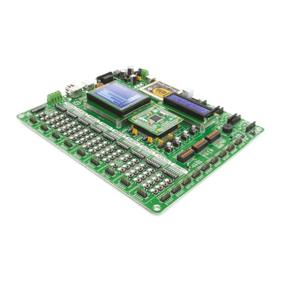
- Page 1 EasyMx PRO for STM32 ® ® microcontrollers supported Many on-board modules Easily add extra boards Four connectors for each port Fast USB 2.0 programmer and The ultimate STM32 board Multimedia peripherals mikroBUS sockets Amazing Connectivity In-Circuit Debugger ® ™...
- Page 2 It may be our first STM32® development board, but it sure looks and feels like it's our 7th. You made the right choice. But the fun has only just begun! Nebojsa Matic, Owner and General Manager of mikroElektronika...
-
Page 3: Table Of Contents
Introduction Communication Introduction ........USB-UART A . -
Page 4: Introduction
Introduction ARM® Cortex -M3 and Cortex -M4 are increasingly popular ™ ™ microcontrollers. They are rich with modules, with high performance and low power consumption, so creating a development board the size of EasyMx PRO v7 for STM32® was really a challenge. We wanted to put ™... -
Page 5: It's Good To Know
Package contains 20122011 www.mikroe.com Copyright ©2011 Mikroelektronika. All rights reserved. Mikroelektronika, Mikroelektronika logo and other Mikroelektronika trademarks are the property of Mikroelektronika. All other trademarks are the property of their respective owners. Unauthorized copying, hiring, renting, public performance and broadcasting of this DVD prohibited. -
Page 6: Power Supply
Power supply Board contains switching power supply that creates stable voltage and current levels necessary for powering each part of board. Power supply section contains specialized MC33269DT3.3 power regulator which creates VCC-3.3V power supply, thus making the board capable of supporting 3.3V microcontrollers. - Page 7 Power supply: via DC connector or screw terminals (7V to 23V AC or 9V to 32V DC), Board power supply creates stable 3.3V necessary for or via USB cable (5V DC) operation of the microcontroller and all on-board modules. Power capacity: up to 500mA with USB, and up to 600mA with external power supply How to power the board?
-
Page 8: Default Mcu Card
Default MCU card Microcontrollers are supported using specialized MCU cards containing 104 pins, package is shown on Figure 4-1. It contains STM32F107VCT6 microcontroller with which can be placed into the on-board female MCU socket. There are several types on-chip peripherals and is a great choice for both beginners and professionals. After of cards which cover all microcontroller families of STM32®... - Page 9 VREF 100nF 100nF 100nF 100nF 100nF 100nF 100nF 10uF 10uF R1 100K PB12 PA2_MDIO PB12 PB13 PB13 LED1 LED2 PB14_nINT PB14 PA0-WKUP SPI_SCK VREF PB15 VDDA SPI_MOSI SPI_MISO VREF VREF+ RST# VREF- PD11 PD10 PD10 PC13 PD10 GNDA PD13 PD12 PD11 PD11 PD15...
- Page 10 How to properly place your MCU card into the socket? Before you plug the microcontroller card into the v7 STM32® board MCU socket. Place the everything is placed correctly and press the MCU ™ socket, make sure that the power supply is turned MCU card over the socket, so each male header is card until it is completely plugged into the socket off.
-
Page 11: Other Supported Mcu Cards
Other supported MCU cards mikroElektronika currently offers total of three populated MCU cards. Two with becomes truly flexible and reliable tool for almost any of your ARM® projects. MCU -M3: STM32F107VCT6 microcontroller (default), STM32F207VGT6 Cortex cards can also be used in your final devices. For complete list of currently available ™... -
Page 12: On-Board Programmer
On-board programmer What is mikroProg ™ mikroProg is a fast programmer and debugger which is based on ST-LINK V2 programmer. Smart engineering allows ™ mikroProg ™ to support over 180 ARM® Cortex ™ -M3 and Cortex ™ -M4 devices from STM32® in a single programmer. It also features a powerful debugger which will be of great help in your development. -
Page 13: List Of Mcus Supported With Mikroprog
STM32 Cortex -M3 microcontrollers supported with mikroProg ® ™ ™ STM32F100C4 STM32F101R6 STM32F102C6 STM32F103V8 STM32F205RE STM32F215RE STM32L151VC STM32F100C6 STM32F101R8 STM32F102C8 STM32F103VB STM32F205RF STM32F215RG STM32L151VD STM32F100C8 STM32F101RB STM32F102CB STM32F103VC STM32F205RG STM32F215VE STM32L151ZC STM32F100CB STM32F101RC STM32F102R4 STM32F103VD STM32F205VB STM32F215VG STM32L151ZD STM32F100R4 STM32F101RD STM32F102R6 STM32F103VE STM32F205VC... -
Page 14: Installing Programmer Drivers
Copyright ©2011 Mikroelektronika. All rights reserved. Mikroelektronika, Mikroelektronika logo and other Mikroelektronika trademarks are the property of Mikroelektronika. All other trademarks are the property of their respective owners. Unauthorized copying, hiring, renting, public performance and broadcasting of this DVD prohibited. -
Page 15: Programming Software
DVD://download/eng/software/development-tools/arm/mikroprog/ mikroprog_suite_for_arm_v110.zip Copyright ©2011 Mikroelektronika. All rights reserved. Mikroelektronika, Mikroelektronika logo and other After downloading, extract the package and double click the Mikroelektronika trademarks are the property of Mikroelektronika. All other trademarks are the property of their respective owners. -
Page 16: Hardware Debugger
Supported Compilers All MikroElektronika compilers, mikroC , mikroBasic ™ ™ mikroPascal ™... - Page 17 Debugger commands Here is a short overview of which debugging commands are supported in mikroElektronika compilers. You can see what each command does, and what are their shortcuts when you are in debugging mode. It will give you some general picture of what your debugger can do.
-
Page 18: Input/Output Group
Input/Output Group One of the most distinctive features of EasyMx v7 for STM32® are it’s Input/Output PORT ™ groups. They add so much to the connectivity potential of the board. Everything is grouped together Figure 6-1: I/O group contains PORT header, tri-state pull PORT headers, PORT buttons and PORT LEDs are next to each other, and grouped up/down DIP switch, buttons and LEDs all in one place together. -
Page 19: Reset Button
RESET button, which DIP switch on SW15 (Figure through SW15.8 6-6). can be used to manually reset the Figure 6-4: IDC10 male headers enable easy switches are used to microcontroller. connection with mikroElektronika accessory boards enable PORT LEDs EasyMx PRO page 19... -
Page 20: Mikrobus ™ Sockets
Success of the USB standard comes from it’s simplicity of usage and high and reliable data mikroBUS host connector ™ transfer rates. As we in mikroElektronika see it, mikroBUS pinout explained ™ Plug-and-Play devices with minimum settings are the future in embedded world too. This is... -
Page 21: Click Boards
™ ™ Click Boards are plug-n-play! ™ mikroElektronika’s portfolio of over 200 accessory boards is now enriched with literally zero hardware configuration. Just plug and play. Visit the Click compatible Click Boards by an additional set of mikroBUS ™ . Almost each... -
Page 22: Usb-Uart A
TX and RX lines to PA9 and PA10 establish this connection, you must connect RX and Copyright ©2011 Mikroelektronika. All rights reserved. Mikroelektronika, Mikroelektronika logo and other Mikroelektronika trademarks are the property of Mikroelektronika. All other trademarks are the property of their respective owners. -
Page 23: Usb-Uart B
TX and RX lines to PD5 and PD6 Copyright ©2011 Mikroelektronika. All rights reserved. Mikroelektronika, Mikroelektronika logo and other Mikroelektronika trademarks are the property of Mikroelektronika. All other trademarks are the property of their respective owners. microcontroller pins and its UART Unauthorized copying, hiring, renting, public performance and broadcasting of this DVD prohibited. -
Page 24: Usb Host Communication
USB HOST communication USB is the acronym for Universal Serial Bus. This is a very popular industry standard that defines cables, connectors and protocols used for communication and power supply between computers and other v7 for STM32® contains USB HOST connector (CN24) for USB Standard Type A plug, devices. -
Page 25: Usb Device Communication
USB device communication EasyMx PRO v7 for STM32® also contains USB DEVICE connector (CN26) which enables ™ microcontrollers that support USB communication to establish a connection with the target host (eg. PC, Laptop, etc). It lets you build a slave USB device (HID, Composite, Generic, etc.). Detecting connection Connector supports USB Standard Type B plug. -
Page 26: Ethernet Communication
Ethernet communication Ethernet is a popular computer networ king VCC-3.3V LD75 technology for local area networks (LAN). LED2 LED2 Ethernet MCU cards Systems communicating over Ethernet VCC-3.3V divide a stream of data into individual TX_P packets called frames. Each frame contains CN25 source and destination addresses and TX_N... -
Page 27: Can Communication
communication Controller Area Network (CAN or CAN VCC-3.3V bus) is a vehicle bus standard designed Enabling CAN to allow microcontrollers and devices to R57 10 communicate with each other within a Figure 13-2: TX-CAN CANH vehicle without a host computer. CAN CANH enabling is a message-based protocol, designed... -
Page 28: Audio Input/Output
Audio I/O It's hard to imagine modern multimedia devices without high quality audio reproduction modules. Sounds and music are almost as important as graphical user interfaces. Along with other multimedia modules, EasyMx PRO v7 for STM32® contains high ™ end stereo VS1053 audio codec. It features Ogg Vorbis/MP3/AAC/WMA/FLAC/ WAVMIDI audio decoder, as well as an PCM/IMA ADPCM/Ogg Vorbis encoder on a single chip. -
Page 29: Microsd Card Slot
microSD card slot Secure Digital (SD) is a non-volatile DATA BUS memory card format developed for use Enabling microSD VCC-MMC VCC-3.3V in portable devices. It comes in different PH_SCK MCU_SCK packages and memory capacities. It is PH_MISO MCU_MISO PH_MOSI MCU_MOSI FERRITE mostly used for storing large amounts of data. -
Page 30: Tft Display 320X240Px
TFT display 320x240 pixels One of the most powerful ways of presenting data Each pixel is capable of showing 262.144 different colors. and interacting with users is through color displays TFT display is connected to microcontroller PORTE using and touch panel inputs. This is a crucial element of any standard 8080 parallel 8-bit interface, with additional multimedia device. -
Page 31: Touch Panel Controller
Touch Panel controller Touch panel is a glass panel whose surface is covered equipped with touch panel controller and connector for with two layers of resistive material. When the screen 4-wire resistive touch panels. It can very accurately is pressed, the outer layer is pushed onto the inner layer register pressure at a specific point, representing the and appropriate controllers can measure that pressure touch coordinates in the form of analog voltages, which... -
Page 32: Glcd 128X64
GLCD 128x64 Graphical Liquid Crystal Displays, or GLCDs display connector. Board is fitted with uniquely designed are used to display monochromatic graphical plastic display distancer, which allows the GLCD module to content, such as text, images, human-machine perfectly and firmly fit into place. interfaces and other content. -
Page 33: Navigation Switch
Navigation switch When working with multi media applications it is far more intuitive to use a single joystick than several different push buttons that are more far apart. This is more natural for users and they can browse through on-screen menus, or even play games much easier. -
Page 34: Ds1820 - Digital Temperature Sensor
DS1820 - Digital Temperature Sensor DS1820 is a digital tempera- of 750ms for the DS1820 to calculate sensors can be connected on the same ture sensor that uses 1-wire® temperature with 9-bit resolution. line. All slave devices by default have interface for it’s operation. -
Page 35: Lm35 - Analog Temperature Sensor
LM35 - Analog Temperature Sensor The LM35 is a low-cost precision obtain convenient Centigrade scaling. Board provides a separate integrated-circuit temperature sensor, It has a linear +10.0 mV/°C scale factor socket (TS2) for the LM35 whose output voltage linearly and less than 60 μA current drain. As it sensor in TO-92 plastic draws only 60 μA from its supply, it has packaging. -
Page 36: Serial Flash
Serial Flash Memory Flash memory is a non-volatile storage chip that can be electrically erased and reprogrammed. It Enabling Serial Flash was developed from EEPROM (electrically erasable programmable read-only memory) and must be erased in fairly large blocks before these can be rewritten with new data. -
Page 37: I 2 C Eeprom
C EEPROM EEPROM is short for Electrically Erasable Programmable Read Only Memory. It is usually Enabling I C EEPROM a secondary storage memory in devices containing data that is retained even if the device looses power supply. Because of the ability to alter single bytes Figure of data, EEPROM devices are used to store personal 23-2: Turn... -
Page 38: Adc Inputs
ADC inputs Digital signals have two discrete states, which are decoded as high and low, and interpreted as logic 1 and logic 0. Analog signals, Enabling ADC inputs on the other hand, are continuous, and can have any value within defined range. A/D converters are specialized circuits which can convert analog signals (voltages) into a digital representation, usually in form of an integer number. -
Page 39: Piezo Buzzer
Piezo Buzzer Piezo electricity is the charge which accumulates in ones. Frequency of the square signal determines certain solid materials in response to mechanical pressure, the pitch of the generated sound, and duty cycle of but also providing the charge to the piezo electric material the signal can be used to increase or decrease the causes it to physically deform. -
Page 40: Additional Gnds
Additional GNDs EasyMx PRO v7 for STM32® contains GND pins located in different sections of ™ the board, which allow you to easily connect oscilloscope GND reference when you monitor signals on microcontroller pins, or signals of on-board modules. GND is located below microSD section. GND is located just above PORTE/H Input/Output Group. - Page 41 ™ ™ www.mikroe.com Copyright ©2011 Mikroelektronika. All rights reserved. Mikroelektronika, Mikroelektronika logo and other Mikroelektronika trademarks are the property of Mikroelektronika. All other trademarks are the property of their respective owners. Unauthorized copying, hiring, renting, public performance and broadcasting of this DVD prohibited.
- Page 42 EasyMx PRO page 42...
- Page 43 (including damages for loss of business profits and business information, business interruption or any other pecuniary loss) arising out of the use of this manual or product, even if MikroElektronika has been advised of the possibility of such damages.
- Page 44 If you are experiencing some problems with any of our products or just need additional information, please place your ticket at www.mikroe.com/esupport If you have any questions, comments or business proposals, do not hesitate to contact us at office@mikroe.com EasyMx PRO v7 for STM32 ® User Manual ver. 1.01 0 100000 019610...
Need help?
Do you have a question about the EasyMx PRO v7 and is the answer not in the manual?
Questions and answers