Table of Contents
Advertisement
CC
PAC
MOSFET
1
~
PHASE
DC
SUPERCUT 50/50P PLASMA CUTTER
Safety, Setup and General Use Guide
everlastwelders.com
EVERLAST
SUPERCUT SERIES
Mosfet inverter plasma cutter
Operator's Manual For
1-877-755-9353
329 Littlefield Ave. South San Francisco, CA 94080 USA
Rev. 1
Specifications and Accessories subject to change without notice.
0 00422-14
Advertisement
Table of Contents

Subscribe to Our Youtube Channel
Related Manuals for Everlast Supercut Series


Summary of Contents for Everlast Supercut Series
- Page 1 EVERLAST SUPERCUT SERIES Mosfet inverter plasma cutter MOSFET PHASE Operator’s Manual For SUPERCUT 50/50P PLASMA CUTTER Safety, Setup and General Use Guide Rev. 1 0 00422-14 everlastwelders.com Specifications and Accessories subject to change without notice. 1-877-755-9353 329 Littlefield Ave. South San Francisco, CA 94080 USA...
-
Page 2: Table Of Contents
The owner of this product assumes all liability for its use and maintenance. Everlast Power Equipment INC. does not warrant this product or this document for fitness for any particular purpose, for performance/accuracy or for suitability of application. -
Page 3: Letter To The Customer
Your unit registration is important should any information such as product updates or re- calls be issued. It is also important so that we may track your satisfaction with Everlast products and services. If you are unable to register by website, contact Everlast directly through the sales department through the main customer service number in your country. -
Page 4: Everlast Contact Information
Model number: ____________________________ Date of Purchase___________________________ EVERLAST Contact Information Everlast US: Everlast consumer satisfaction email: sales@everlastwelders.com Everlast Website: everlastwelders.com Everlast Technical Support: support@everlastwelders.com Everlast Support Forum: http://www.everlastgenerators.com/forums/index.php Main toll free number: 1-877-755 WELD (9353) 9am—5pm PST M-F 11am-4pm PST Sat. -
Page 5: Safety Precautions
Safe operation and proper maintenance is your responsibility. We have compiled this operator’s manual, to instruct you in basic safety, oper- ation and maintenance of your Everlast product to give you the best possible experience. Much of welding and cutting is based upon experience and com- mon sense. - Page 6 SAFETY PRECAUTIONS These safety precautions are for protection of safety and health. Failure to follow these guidelines may result in serious injury or death. Be careful to read and follow all cautions and warnings. Protect yourself and others. Welding and cutting processes produce high levels of ultraviolet (UV) radiation that can cause severe skin burn and damage.
- Page 7 SAFETY PRECAUTIONS WARNING! Persons with pacemakers should not weld, cut or be in the welding area until they consult with their physician. Some pacemakers are sensitive to EMF radiation and could severely malfunction while welding or while being in the vicinity of someone welding.
- Page 8 SAFETY PRECAUTIONS continued WARNING! Electrical shock can kill. Make sure all electrical equipment is properly grounded. Do not use frayed, cut or otherwise damaged cables and leads. Do not stand, lean or rest on ground clamp. Do not stand in water or damp areas while weld- ing or cutting.
-
Page 9: Introduction And Specifications
AG-60 12 ft. Plasma Torch NOTE: Accessory and consumable style and quantities are subject to change without notice. Consumable starter kits provide only enough consumables to get started. Extra consumables can be purchased through Everlast or almost any local welding supply store. -
Page 10: Unit Specifications
Plan the unit’s daily use around the recommended average cut thickness for best results and speed. This is an industry standard recommendation and is not unique to Everlast Plasma Cutters. Plasma performance specifications are based on reasonable environmental conditions with well maintained units, and cutting with new consumables using optimum air pressure. -
Page 11: General Overview
Introduction and Specifications Section 1 General overview: The Supercut 50 and 50P plasma Duty Cycle. The duty cycle has been determined for the cutters feature a light weight MOSFET inverter design. PowerPlasma at 60% @ 50 amps on 240 V operation. The entry level SuperCut 50 and 50P are designed to The duty cycle is based off a 10 minute duty cycle rating at meet the demands of people having occasional plasma... -
Page 12: Quick Setup Guide, Plasma Connections
If it remains below 30 amps (usually 20-27 amps or so) the pilot arc is not transferring. Stop and examine the work piece, clamp and even the DINSE connector on the panel. Repair if necessary. If this does not resolve the pilot arc transfer issue, contact Everlast. -
Page 13: Quick Setup Guide, Rear Connection For Plasma
Section 2 QUICK SETUP AND USE GUIDE QUICK SETUP GUIDE: REAR CONNECTIONS FOR PLASMA OPERATION Compressor and Dryer Diagram Compressor and Air hose w fittings (Customer Supplied) Regulator Assembly with built-in water trap and dirt filter (Included). Pull knob to set, push to lock in place 1/4”... -
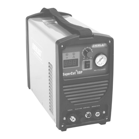
Page 14: Front Panel Features And Controls
Section 2 QUICK SETUP AND USE GUIDE FRONT PANEL FEATURES AND CONTROLS 1. AMP CONTROL 2. ON/TEMP/O.C. 3. AMP DISPLAY 8. AIR PRESSURE 4. MANUAL/AUTO FLOW SWITCH TORCH PILOT ARC CONTROL WORK PIECE 7. WORK CLAMP (25 SERIES) 5. TORCH CONNECTOR 7. - Page 15 Cycle the power switch to reset the machine. The light should go off if the problem is remedied. If it does not go off, check for external fault. If no fault is found, contact Everlast. 3. Amp Display Indicates amperage while cutting.
-
Page 16: Rear Panel Features And Controls
Section 2 QUICK SETUP AND USE GUIDE REAR PANEL FEATURES AND CONTROLS 5. REGULATOR ASSY. 1. POWER SWITCH 2. POWER CABLE 1 ~ 120/240V INLET 4. HF GROUND BOLT 3. GAS INLET GREEN GROUND (240V ) L1,BLACK; HOT(240V ) L2 WHITE, HOT(240V ) NEMA 6-50P Note: Customer Supplies Plug. -
Page 17: Plasma Function And Operation
5% is preferred. Operating the unit on square wave output or modified sine wave generator is strictly prohibited. Contact the manufacturer of the genera- tor for this information. Everlast does not have an “approved” list of generators. But, if the generator is not listed as clean power by its manufacturer, then operation is prohibited. - Page 18 Section 3 Basic theory and function Helpful Hint: If difficulty is observed in starting the arc, it may be time to readjust the point gap setting found inside. The HF points tend to wear and get dirty over time. This is a normal maintenance item and not something for warranty consideration. Proper point gap adjustment is .035 “vto .045”.
- Page 19 Section 3 Basic theory and function TIP: For longer consumable life do not use the pilot arc unnecessarily. Rapid wear will oc- cur if the pilot arc stays engaged more than 3 seconds at a time. FLAME AT NORMAL TRAVEL SPEED FLAME AT FAST TRAVEL SPEED TRAVEL TRAVEL...
- Page 20 Section 3 Basic theory and function RESULTS OF CUT AT CORRECT SPEED, RESULTS OF CUT AT FAST SPEED AIR PRESSURE AND TORCH ANGLE ROUGH, DISTINCT CUT LINES SPACED FAR APART SMOOTH, EVEN CUT LINES WITH A S REARWARD SWEEP MINIMAL EASY TO CLEAN DROSS NOTICEABLE SMALL, HARD DROSS RESULTS OF TOO MUCH CURRENT OR RESULTS OF CUT AT SLOW SPEED...
- Page 21 Section 3 Basic theory and function AN EXAMPLE OF CUTTING A LEAD-IN WHEN CUTTING OUT A DISK SHAPED OBJECT AN EXAMPLE OF CUTTING A LEAD-IN WHEN CUTTING HOLE IN AN OBJECT When cutting an object, particularly a pattern shape, where the torch must pierce or re-fire in-line at an inter- section of a cut, a lead-in cut should be employed.
-
Page 22: Plasma Torch
Section 3 Basic theory and function AG60/SG 55 PLASMA TORCH ITEM DESCRIPTION PART NUMBER/SKU Torch Head/Body E-WSD-061 Electrode 1.0mm E-AG60-TIP Tip/Nozzle E-AG60-EL Shielding Cup E-AG60-CUP... -
Page 23: Troubleshooting
Stuck or dirty solenoid valve. Contact Everlast. flow while switch is pressed. Air flows continuously. Unit set to Manual Flow. Solenoid is stuck. Contact Everlast. Excessively Beveled Cut. Worn consumables, too high of stand-off height. Cup and/or nozzle is melting/cracking.
Need help?
Do you have a question about the Supercut Series and is the answer not in the manual?
Questions and answers