Table of Contents
Advertisement
Quick Links
Publish Date: 8-14-2022
EVCYCLONE262 Rev. 1
USA/North America
©Everlast Power Equipment
DC
275A
DC
200A
240V 1Ph
Welders, Plasma Cutters, Multi-Process
Safety, Setup and General Use Guide For The
Operator's Manual
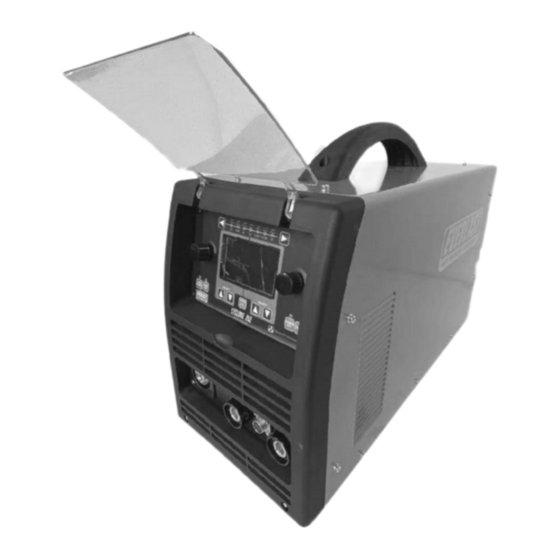
Cyclone 262
FUNCTION: MIG/Stick Welder
PURCHASE DATE:
MODEL NAME:
SERIAL NUMBER:
OPTIONAL ACCESSORY SERIAL NUMBER:
Advertisement
Table of Contents

Related Manuals for Everlast Cyclone 262


Summary of Contents for Everlast Cyclone 262
- Page 1 Publish Date: 8-14-2022 EVCYCLONE262 Rev. 1 USA/North America ©Everlast Power Equipment 275A Safety, Setup and General Use Guide For The Cyclone 262 200A FUNCTION: MIG/Stick Welder PURCHASE DATE: MODEL NAME: SERIAL NUMBER: OPTIONAL ACCESSORY SERIAL NUMBER: Operator’s Manual 240V 1Ph...
-
Page 2: Table Of Contents
TABLE OF CONTENTS SPECIAL NOTICE AND CALIFORNIA PROPOSITION 65 WARNING CUSTOMER GREETING AND EXPLANATION OF PROCEDURES WARRANTY AND CONTACT INFORMATION SAFETY DISCLAIMER AND HF WARNING SAFETY WARNINGS, DANGERS, CAUTIONS AND INSTRUCTIONS GENERATOR OPERATION INFORMATION REAR OUTLET INFORMATION SPECIFICATIONS DUTY CYCLE INFORMATION BREAKER AND WIRING REQUIREMENT INFORMATION OPERATING AND ELECTRICAL SPECIFICATIONS GETTING STARTED, UNPACKING YOUR UNIT AND INSPECTION... -
Page 3: Special Notice And California Proposition 65 Warning
Due to multiple variables that exist in the welding field and the changing nature of it and of the Everlast product line, Everlast Power Equipment INC. does not guarantee the accuracy, completeness,... -
Page 4: Customer Greeting And Explanation Of Procedures
Many issues can be resolved over the phone. If the issue cannot be resolved over the phone/email, you may be given an op- tion to return the unit, or have a part shipped to you, at Everlast’s discretion. Keep in mind, you may be asked questions that seem basic, or ele- mentary to your knowledge base. -
Page 5: Warranty And Contact Information
Warranties and service policies and procedures vary from country to country and are maintained and supported by the region- al or in country distributor of Everlast welding equipment. USA Customers Only: For full details on the 5 year parts and labor warranty, 30 day satisfaction policy, terms of sale, and how to proceed with a war- ranty claim, please visit: https://www.everlastgenerators.com/standard-warranty. -
Page 6: Safety Disclaimer And Hf Warning
Safe operation and proper maintenance is your responsibility. Everlast is dedicated to keeping safety a top priority. While we have compiled this operator’s manual to instruct you in basic safe operation and maintenance of your Everlast product, it is no substitute for observing safe welding practices and behavior. Safe welding and related cutting operations require basic knowledge, experience and ultimately the exercise of common sense. -
Page 7: Safety Warnings, Dangers, Cautions And Instructions
It is your responsibility to make certain that the use of this welder is restricted to per- sons who have read, understand and follow the warnings and instructions in this manual. If you or the operator needs further instruction, contact Everlast welding support at 1-877 755 -9353 ext. 204 or seek qualified professional advice and training. - Page 8 Safety Warnings, Dangers, Cautions and Instructions DANGER! Welding and cutting operations pose serious inhalation hazards. Some of these hazards are immediate while others are cumulative in their effect. Do not weld in enclosed spaces or in areas without adequate ventilation. Fumes and gases released in the welding and cutting operations can be toxic.
- Page 9 Safety Warnings, Dangers, Cautions and Instructions CAUTION! Trip Hazards exist around this unit. Cords, cables, welding leads and hoses pose a trip hazard. Be aware of their location and inform others of their location. Tape and secure them so they will stay out of high traffic areas. CAUTION! Welded metal can stay hot long after welding is completed.
-
Page 10: Generator Operation Information
This outlet is designed to supply 240V only. Do not attempt to modify, or change this outlet for use with anything else other than an Everlast brand water cooler designed for 240V operation. Severe damage, fire or injury may oc-... -
Page 11: Specifications
Specifications Duty Cycle Duty Cycle is simply the amount of time out of a 10 minute period in which the unit can operate. For example, this unit has a duty cycle of 50% at maximum output (MIG or Stick). This means the unit can be operated for 5 minutes out of 10 minutes. The unit may be operated be continuously, or intermittently for 5 minutes during the 10 minute period of time while the machine is MIG welding at maximum output. -
Page 12: Breaker And Wiring Requirement Information
Use the I1MAX and the I1EFF ratings listed above to determine the proper breaker and con- ductor (wire) sizing required. Everlast welders are designed around use in industrial wiring applications and are intended to be used with modern elec- trical systems. -
Page 13: Operating And Electrical Specifications
National Electric Code (NEC) and local codes. If needed, refer the electrician to Article 630 of the NEC during consultation to determine proper application and wiring needs. Use the I1MAX and the I1EFF ratings listed above to determine the proper breaker and conductor (wire) sizing required. Everlast welders are designed around use in industrial wiring applications and are intended to be used with modern electrical systems. -
Page 14: Getting Started, Unpacking Your Unit And Inspection
The air is then ex- -groove shape. Any 4 roll drive rolls (2 pc kits) offered by Everlast hausted through the front panel and side louvers of the unit. If any of will fit this unit. -
Page 15: Connecting Your Unit To The Power Source And Wiring Information
Do not wire connections for this machine if you are not conductors and ground) are black, white and green. A red wire, which qualified. Everlast is in no way liable for any damages caused by im- is traditionally used as a “hot” leg (power conducting wire) of power proper connection of this unit. -
Page 16: Shielding Gas,Regulators, And Torch Installation And Polarity Information
Connect the regulator tubing to the regulator. The regulator may be The Cyclone 262 is a synergic unit which incorporates the type of supplied with a hose barb connection, or a threaded connection for gas and metal wire being welded with as a base to make accurate the tubing (depending upon region). - Page 17 Setup Guide Getting Started The on screen programming will remind you what polarity to use, but machine. Failure to change polarity will result in erratic operation, bird’s in case you forget, refer to the illustrations below. nesting of the wire, poor fusion and excess spatter. Use illustrations below as a guide.
- Page 18 .040” or .045” 1.0mm or 1.2mm U groove. spite the mode that has been selected. The power is not disconnected Contact Everlast to verify the sizes you expect to need and order them to the output terminals on the machine while welding other process- direct.
-
Page 19: Installing Mig Wire And Drive Roll Selection, Mig Gun Disassembly And Setup
Setup Guide Getting Started CHECK AND CHANGE YOUR DRIVE ROLL. INSTALL THE WIRE AND FEED THE GUN. The unit comes with a pair of .035” and .045” drive rolls installed. Once the wire spool has been installed, flip the tensioner lever down Remember, if you change wire size or type, you will need to either flip and raise the top drive rolls to the upper position. - Page 20 Setup Guide Getting Started threaded through the wire feeder mechanism and gun. • Increase wire tension so that the wire contacts the block of wood and is forced to curl up. Continue holding the trigger so TRIM THE WIRE AFTER INSTALLATION. that two or three full spirals are made.
-
Page 21: Front Panel View And Component Id
Component Identification and Explanation Front Panel View Number Component Identification Component Note Protective Cover Keep cover down and in place during welding activities and in storage. Euro-Style Quick Connector Connect this to the MIG gun or Spool Gun. Positive Terminal (+) For Stick, connect to the Torch. -
Page 22: Rear Panel View And Component Id
240V Cooler Outlet This is a low Amp 240V receptacle. Use only with Everlast 240V coolers. Other use may cause damage or fire. Do not attempt to modify this receptacle or wiring. This outlet is switched via the main power switch and will not supply power while the machine is off. -
Page 23: Control Panel Layout
The left adjustment knob is used change the desired status of a function (i.e. voltage, turn on/off, electrode type, thickness Left Adjustment etc.) and to set all adjustable values to the left side of the black dividing hash mark just above the “EVERLAST” logo. If you Knob push in on the knob while adjusting, it will adjust in larger increments, usually in whole numbers or increments of 10. - Page 24 Component Identification and Explanation Getting Ready To Weld rameter area, the large white numbers will appear to dim. After 4 to 5 GENERAL INFORMATION ON SETUP AND USE. seconds if you haven’t made another selection or made an adjustment to the function or parameter selection, the machine automatically defaults back to the main parameter area and the numbers will bright- en and will be able to be adjusted.
- Page 25 Component Identification and Explanation Getting Ready To Weld PRGRM/SAVE/RECALL button to return to the program screen. Use the navigation buttons to highlight the desired program. Quickly press and release the PRGRM/SAVE/RECALL button to recall and open the program. If the program needs to be fine tuned, the set- tings may be adjusted or changed while in use.
-
Page 26: Getting Ready To Weld/Setting Up The Unit For Welding Manually
Component Identification and Explanation Setting the Unit Up For Welding Manually right arrows ( ) at the top of the panel to select the desired THE WELCOME/BOOT SCREEN process. Be sure to wait until this screen is present before you at- tempt any change of the welding process. - Page 27 Component Identification and Explanation Setting the Unit Up For Welding Manually (IPM) and in Meters Per Minute) m/Min. This is the default be listed as N/A. setting for the right side After 5 seconds of no input, When the 10. Post Flow. The unit has an adjustable post-gas flow setting. Wire Feed Speed is selected for adjustment the display will This is complimentary to the Preflow setting and also serves to brighten in color.
- Page 28 Component Identification and Explanation Setting the Unit Up For Welding Manually 14. Stitch Timer. This function works only in conjunction with the Manual/PowerSet Mode. This indicates which mode the ma- Spot timer. This provides a continuous “on/off” action of the chine is operating in, whether in full manual mode or in Pow- spot timer, allowing the user to move smoothly and evenly erSet mode which is a synergic, more automated mode.
-
Page 29: Setting Up The Powerset Mode
Component Identification and Explanation Setting the Unit Up PowerSet Mode bottom right side of the panel by pressing the button briefly. The LED UNDERSTANDING POWERSET. above the PowerSet button will illuminate. This will activate the Pow- The PowerSet mode, regardless of process selected is designed to erSet Screen for the process you are using. - Page 30 Component Identification and Explanation Setting the Unit Up PowerSet Mode bered value (4) will turn red. If you find that you have moved too far off the suggest setting of the machine, all you will need to do is turn the adjustment knob until you are back at the center, tallest bar.
-
Page 31: Explanation Of Mig Functions And Terms
Component Identification and Explanation Explanation of MIG Functions and Terms EXPLANATION OF WELDER FUNCTIONS bacon should be heard. The actual frying sound can vary somewhat and may have somewhat of a higher pitch whine to it. If these sounds are present, look at the arc to see if it is steady, and producing low amounts of spatter. - Page 32 Component Identification and Explanation Explanation of MIG Functions and Terms well versed in MIG quickl develop a sense of when to push and when to rust and mill scale, but when MIG welding, contaminates will result in pull the gun. Even for novices, a sense of when to push and pull the gun porosity and inclusions in the weld, weakening it.
- Page 33 Component Identification and Explanation Explanation of MIG Functions and Terms resulting in poor tie in. One issue created with a weaving technique even Joint Preparation if the metal deposited is the correct thickness is that it can slow the for- ward progress down.
- Page 34 Component Identification and Explanation Explanation of MIG Functions and Terms MIG Welding is fairly simple if you keep travel angle and direction in mind when welding. See below. If you are welding flux- core, the gun direction is reversed. Remember: If it has gas, you use a push angle. If it is gas-less you use a drag angle. The old welder’s saying “If it has slag, you drag.”...
-
Page 35: Mig Torch Component Breakdown
The .023” diameter wire should not be used in a gun over 10ft (3m). The .030” wire diameter should not be used in a gun over 12.5 feet (4m) Purchase of an optional liner and possibly a smaller series gun such as the 15 or 24 series, which are available from Everlast, is recommended for use with these smaller sizes for best performance. -
Page 36: Stick Welding Information
Component Identification and Explanation Stick Welding Information STICK ARC STARTING METHODS Make sure the unit is turned on and the boot cycle has finished. Select the Stick Process on the Selector. Make sure the electrode holder is in the Positive connector and the work clamp is in the negative connector. Select the Amp level desired. - Page 37 Component Identification and Explanation Stick Welding Information HELPFUL HINT: Pay particular attention to the Arc Force setting as it affects the ag- gressiveness of the arc and the amp response. Set the Arc force to approximately 30-50% and readjust it from that point to find the optimum setting.
-
Page 38: Common Mig/Flux Cored Issues
Check gas flow. Adjust for higher flow of gas. Listen for audible click Weld is dirty/oxidized, or porous. Solenoid is sticking. of gas solenoid. If no click is heard, then contact Everlast Support. Clean weld properly. Increase pre flow or post flow. For Flux Core, a certain amount of spatter, haxe and smoke is common. -
Page 39: Warning Screens/Error Information
Occasionally a warning screen may pop up and interrupt welding. Pay attention to the code and follow the directions. In most cases it will explain the problem and cause. If the condition cannot be resolved, contact Everlast Tech Support for further help and diagnosis.
Need help?
Do you have a question about the Cyclone 262 and is the answer not in the manual?
Questions and answers