Table of Contents
Advertisement
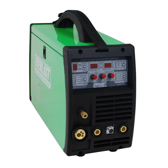
EVERLAST
MTS
POWER
200/250S
CC/CV MULTI-PROCESS WELDER
GMAW/GTAW/SMAW
CC
CV
GMAW
GTAW
SMAW
IGBT
DC
Operator's Manual for the Power MTS 200/250S
Safety, Setup and General Use Guide
Rev. 3
0 101009-13
everlastwelders.com
Specifications and Accessories subject to change without notice.
1-877-755-9353
329 Littlefield Ave. South San Francisco, CA 94080 USA
Advertisement
Table of Contents

Related Manuals for Everlast POWER MTS 200


Summary of Contents for Everlast POWER MTS 200
- Page 1 200/250S CC/CV MULTI-PROCESS WELDER GMAW/GTAW/SMAW GMAW GTAW SMAW IGBT Operator’s Manual for the Power MTS 200/250S Safety, Setup and General Use Guide Rev. 3 0 101009-13 everlastwelders.com Specifications and Accessories subject to change without notice. 1-877-755-9353 329 Littlefield Ave. South San Francisco, CA 94080 USA...
-
Page 2: Table Of Contents
Set Up Guide and Component Identification….…... Suggested Settings…….…………………...…….. Connections and Polarity…………………………. Installing MIG Wire ……..………...………………. Front View Power MTS 200………………….…… Front View Power MTS 250S…………………..… Front Panel Item Description and Function…..…. Side View (MTS 200 and 250S)……….…………. Side View Item Description and Function…….. - Page 3 Your unit registration is important should any information such as product updates or re- calls be issued. It is also important so that we may track your satisfaction with Everlast products and services. If you are unable to register by website, contact Everlast directly through the sales department at the main customer service number in your country.
-
Page 4: Everlast Contact Information
Model number: ____________________________ Date of Purchase:___________________________ EVERLAST Contact Information Everlast US: Everlast consumer satisfaction email: sales@everlastwelders.com Everlast Website: everlastwelders.com Everlast Technical Support: support@everlastwelders.com Everlast Support Forum: http://www.everlastgenerators.com/forums/index.php Main toll free number: 1-877-755 WELD (9353) 9am—5pm PST M-F 11am-4pm PST Sat. -
Page 5: Safety Precautions 5
Safe operation and proper maintenance is your responsibility. We have compiled this operator’s manual, to instruct you in basic safety, oper- ation and maintenance of your Everlast product to give you the best possible experience. Much of welding and cutting is based upon experience and com- mon sense. -
Page 6: Safety Precautions
SAFETY PRECAUTIONS These safety precautions are for protection of safety and health. Failure to follow these guidelines may result in serious injury or death. Be careful to read and follow all cautions and warnings. Protect yourself and others. Welding and cutting processes produce high levels of ultraviolet (UV) radiation that can cause severe skin burn and damage. - Page 7 SAFETY PRECAUTIONS WARNING! Persons with pacemakers should not weld, cut or be in the welding area until they consult with their physician. Some pacemakers are sensitive to EMF radiation and could severely malfunction while welding or while being in the vicinity of someone welding.
- Page 8 SAFETY PRECAUTIONS WARNING! Electrical shock can kill. Make sure all electrical equipment is properly grounded. Do not use frayed, cut or otherwise damaged cables and leads. Do not stand, lean or rest on ground clamp. Do not stand in water or damp areas while weld- ing or cutting.
-
Page 9: Introduction And Specifications
Section 1 Introduction and Specifications Overview of Parameters and Features Power MTS 200 MIG TIG STICK Welder PROCESS: GMAW/SMAW/DC GTAW(LIFT START) MIG OUTPUT: 30- 200 A/15.5-24 V DUTY CYCLE @ RATED AMPS: 35% INPUT: 240V 1 phase 50/60 Hz 34 A TIG OUTPUT: 10-200 A WIRE SIZE: .023”-.045”/8”... -
Page 10: Technical Parameters Of Mts 200
Section 1 Introduction and Specifications Power MTS 200 Technical Parameters* EVERLAST MIG/TIG/STICK INVERTER MODEL: PowerMTS 200 EN/ IEC60974.1 DC: 30-200 A 15.5-24 V 100% 200 A 160 A 130 A 22 V 20.5 V DC: 10-200 A ; 10.4-18V 100%... -
Page 11: Technical Parameters Of Mts 250S
Section 1 Introduction and Specifications Power MTS 250S Technical Parameters* EVERLAST MIG/TIG/STICK INVERTER MODEL: PowerMTS 250S EN/ IEC60974.1 DC: 30-250 A ; 15.5-26.5 V 100% 250 A 200 A 160 A 26.5 24 V 22 V DC: 10-250 A ; 10.4-20 V... -
Page 12: General Description, Purpose And Features
Section 1 Introduction and Specifications adjusted while the unit is in operation, offering instant 1.1 General Description, Purpose and Features. The welding response for maximum control. PowerMTS 200 and 250S, are compact lightweight CV/ 1.3 Installation. The basic construction of the CC welders capable of handling most jobsite duties and PowerMTS is rugged and durable, and is considered portable repairs. -
Page 13: Setup Guide And Component Identification
Section 2 Setup Guide and component Identification GENERAL POLARITY RECOMMENDATIONS* Table 1 *Consult manufacturer directions of filler material. There are exceptions! PROCESS TORCH POLARITY WORK POLARITY MIG (GMAW) FLUX CORE (FCAW) TIG (GTAW) STICK (SMAW) GAS SELECTION GUIDE Table 2 PROCESS MIG (GMAW) STEEL 80/20 Ar/CO2 or 75/25 Ar/CO2 (For optimum synergic operation) -
Page 14: Connections And Polarity
Section 2 Setup Guide and component Identification REGULATOR Everlast regulators read in Liters/minute. EVERLAST Customer Supplied. May need to supply additional fittings for connection, depending upon regulator. EVERLAST GAS IN FROM REAR OF WELDER GAS OUT TIG GAS: ARGON ONLY... -
Page 15: Installing Mig Wire
Pull the drive roll off, and flip the drive roll over. Reassemble and tighten roller. If larger roller is needed, contact Everlast. Thread straightened wire into coiled sheath and over grooves in lower drive roll. - Page 16 10. Negative Connector MIG: Work Clamp TIG: Torch Stick: Work Clamp 12. Positive Connector MIG: Spool Gun 13. MIG Torch Euro Connector 11. TIG Torch Switch Foot Pedal Control TIG: Work Clamp Stick: Torch FRONT VIEW/ MAIN PANEL POWER MTS 200...
- Page 17 Section 2 Setup Guide and component Identification 3. LED Indicators: Warning/Function (Multiple) 4. Amp/Wire Speed Display 1. Memory: 1-9 2. Volt/Seconds/Arc Force Display MIG: Wire Speed (while static) TIG: Amps Stick: Amps 5. 2T/4T Pedal Selector 17. Process Selector 6. Slope/Flow Selector 7.
-
Page 18: Front Panel Item Description And Function
Section 2 Setup Guide and component Identification Front Panel: 2 seconds. The 4T function in TIG mode acts simi- 1. Memory. 1-9. Select the channel number desired larly, but in conjunction with the up/ down slope with the button, and make desired adjustments timer. - Page 19 Section 2 Setup Guide and component Identification sound will change as the wave form is adjusted, receptacle and pushing in. Twist the collar on the going from a pitched whine to a frying sizzle. All cable connector to lock in place. Do not use pliers brands with no wave form control have a fixed or other tools to tighten.
-
Page 20: Side View Mts 200 And 250S
Section 2 Setup Guide and component Identification 3. Burn Back Control Timer 2. Polarity Buss Bar 1. Wire Spool Holder Assy. Burn Back 4. Wire Feeder Assy. SIDE VIEW MTS 200 and 250S... -
Page 21: Side View Item Description And Function
You may purchase additional work clamp to reflect the polarity change. If drive roll sizes from Everlast, but the standard the terminal buss bar is oriented to negative, drive roll will work with a wide range of wire then the work clamp should be in the “+”... -
Page 22: Rear Panel View (Mts 200 And 250S)
2. Main Power Switch 3. Power Input Cable GREEN/YELLOW STRIPE (Ground) L1, GREEN 120V L2,WHITE 120V 30/50 AMP EVERLAST 220/240V NEMA 6-50 PLUG SHOWN (Customer Supplied) CONSULT A LICENSED ELECTRICIAN FOR PROPER WIRING AND LOCAL CODES. NOTE: GREEN GROUND WIRE WELDER WIRE COLOR MAY NOT AGREE WITH THE WIRE COLOR FOUND IN OUTLET. -
Page 23: Rear Panel Item Desciption And Function
Section 2 Setup Guide and component Identification Rear Panel: 1. Gas Supply. Connect the Gas regulator hose to this point via the brass barb fitting. (Regulator is customer supplied and not provided as standard equipment at time of publication.) The hose barb connection must be tight to prevent gas leakage. -
Page 24: Synergic And Basic Mig Operation
Section 2 Setup Guide and component Identification SYNERGIC AND BASIC MIG OPERATION Synergic vs. Manual Setup and Operation How Synergic MIG operates: The Synergic function of the PowerMTS 250S allows the user to automatically raise or lower the voltage by using only the amp /wire speed control. - Page 25 Section 2 Setup Guide and component Identification 6. If the MTS 250S is used in the manual mode (MIG), or you are welding with the MTS 200 select the appropri- ate wire feed speed (amp) and voltage to match wire type, and size. Listen for a steady frying sound while weld- ing to give you a key as to when it is adjusted properly.
-
Page 26: Lift Start Tig Operation
Section 2 Setup Guide and component Identification LIFT START TIG OPERATION 3. After contact with the metal, quickly rock the torch 1. Position the edge of the ceramic cup on the metal. 2. Quickly rotate cup so that the tungsten comes back so that the tungsten breaks contact with the metal. - Page 27 Section 2 Setup Guide and component Identification Adjust amps with amp control knob located in the center. Start arc as depicted at the top of the previous page. 7. If using 2T, continue to hold the torch switch until you are ready to stop welding. Release switch. Arc will then cease.
-
Page 28: Stick Operation
Section 2 Setup Guide and component Identification STICK OPERATION STARTING METHODS Scratch/Match Method Tapping Method 1. Turn on unit. Allow unit to cycle through its start up program. 2. Select the Stick icon on the Process Selector. 3. Make sure electrode holder is in in the Positive side and the work clamp is in the negative connector. -
Page 29: Expanded View Of Major Mig Drive Components
Section 2 Setup Guide and component Identification EXPANDED VIEW OF MAJOR MIG DRIVE COMPONENTS* *Some non-significant variation may occur in component details. Not all components are individually serviceable, and are added for detail and explanation of assembly Parts Parts Wire feed motor Locking thumb screw Tensioning Spring Feed roller... -
Page 30: Expanded View Of Mig Torch
Section 2 Setup Guide and component Identification EXPANDED VIEW OF MIG TORCH PARTS Diffuser D.12 14-15AK NOTE: Some components may appear slightly different as design/ Contact Tip 0.8/M6*25 IFT0063 螺丝 M4X6 UNI 6107 supplier changes are made from time to time. At time of publication, 15AK Goose gun neck assy. -
Page 31: Expanded View Of Tig Torch
Section 2 Setup Guide and component Identification EXPANDED VIEW OF TIG TORCH 5/8” PARTS FOR SR 17 TORCH (STYLE MAY VARY) QTY. Long Back Cap with O-Ring Short Back Cap Opt. Torch Head Insulator Collet 1/16 or 3/32 Collet Holder Ceramic Cup #5,6, or 7 Tungsten (customer supplied) Torch Cable... -
Page 32: Trouble Shooting
Section 3 Trouble Shooting TABLE 6 Trouble Possible Cause Solution Switch damaged Replace Unit is switched on, but the Fuse damaged Replace power light isn’t on Power damaged Replace Fan damaged Change it After welding machine is overheating and the fan does Tighten wires, check for dislodged con- Fan power connector is loose not work... -
Page 33: Appendix A: Control Plug Schematic
APPENDIX A: PLUG SCHEMATIC Not Connected Not Connected... -
Page 34: Notes
GENERAL NOTES: 1. While welding aluminum with the Spool gun or MIG gun you must use 100% argon. You cannot use a mix as you would with steel or stainless. 2. While welding aluminum with the Spool gun or MIG gun you must use the next size up tip or a special oversize tip for the wire because the heat will cause the aluminum wire to swell and it will either drag or seize in the tip.
Need help?
Do you have a question about the POWER MTS 200 and is the answer not in the manual?
Questions and answers