Table of Contents
Advertisement
EVERLAST
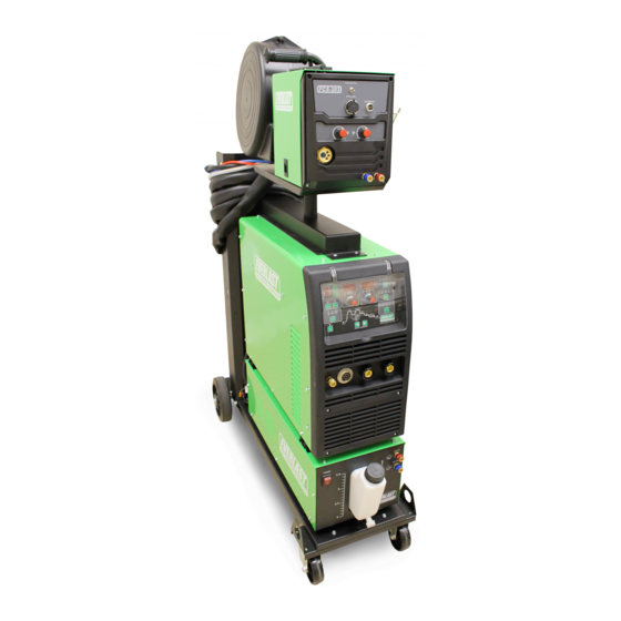
POWER i-MIG 353DPi
A Digitally-Controlled Synergic Pulse MIG with Stick Function
CC
CV
GMAW
SMAW
IGBT
DC
PULSE
Operator's Manual for the Power i-MIG 353DPi
Safety, Setup and General Use Guide
Rev. 1
0 10713-20
everlastwelders.com
Specifications and Accessories subject to change without notice.
1-877-755-9353
380 Swift Ave Unit 12. South San Francisc0, CA 94080 USA
Advertisement
Table of Contents

Related Manuals for Everlast Power i-MIG 353DPi


Summary of Contents for Everlast Power i-MIG 353DPi
- Page 1 POWER i-MIG 353DPi A Digitally-Controlled Synergic Pulse MIG with Stick Function GMAW SMAW IGBT PULSE Operator’s Manual for the Power i-MIG 353DPi Safety, Setup and General Use Guide Rev. 1 0 10713-20 everlastwelders.com Specifications and Accessories subject to change without notice.
-
Page 2: Table Of Contents
TABLE OF CONTENTS Letter to Customer Everlast Contact Information Safety Information Introduction and Specifications General Performance Specifications Electrical Specifications Duty Cycle Explanation and Generator Operation General Feature and Terms Setup Guide Polarity and Gas Selection Guide MIG wire, Gun Connection, Power Source and Wire Feeder Information... -
Page 3: Letter To Customer
This support is free to all Everlast customers. For best service call the appropriate support line and follow up with an email, especially during weekends, holidays or any off hours when you cannot reach a live person. -
Page 4: Everlast Contact Information
The owner of this product assumes all liability for its use and maintenance. Everlast Power Equipment INC. does not warrant this product or this document for fitness for any particular purpose, for performance/accuracy or for suitabil- ity of application. -
Page 5: Safety Information
If you feel you need more information please contact Everlast Support. The content of this manual is not meant to be an exhaustive primer on welding. It is written to an audience that, if not professional, will have at least some basic knowledge of welding terms and practices. - Page 6 Safety Precautions These safety precautions are for protection of safety and health. Failure to follow these guidelines may result in serious injury or death. Be careful to read and follow all cautions and warnings. Protect yourself and others. Welding and cutting processes produce high levels of ultraviolet (UV) radiation that can cause severe skin burn and damage.
- Page 7 Safety Precautions WARNING! Persons with pacemakers should not weld, cut or be in the welding area until they consult with their physician. Some pacemakers are sensitive to EMF radiation and could severely malfunction while welding or while being in the vicinity of someone welding. Serious injury or death may occur! Welding and plasma cutting processes generate electro-magnetic fields and radiation.
- Page 8 Safety Precautions WARNING! Electrical shock can kill. Make sure all electrical equipment is properly grounded. Do not use frayed, cut or otherwise damaged cables and leads. Do not stand, lean or rest on ground clamp. Do not stand in water or damp areas while welding or cutting.
-
Page 9: Introduction And Specifications
.040” to .045” (1.0mm to 1.2mm) for Aluminum, and Bronze (brazing) use. ** Additional Drive Rolls may be ordered direct from Everlast ( 2 pc kit). Size and type stamped on side of the drive roll next to the related groove for easy identification. Synergic Pulse settings for Mild Steel, Stainless Steel, 40XX series Aluminum, 50XX series Aluminum, and Bronze wires. -
Page 10: Electrical Specifications
Section 1 Introduction and Specifications Electrical Specifications EVERLAST POWER i-MIG 353DPi MODEL: POWER i-MIG 353DPi SERIAL NO. EN/ IEC60974.1 DC: 50-350 A; 16.5-31.5V 100% 350 A 280 A 70 V 31.5 V 28 V DC: 10-200 A; 20.4-28 V 100%... - Page 11 LED will be lit. If this happens, immediately shut down the machine, and find the source of the fault. If no fault can be found, turn the unit back on. If the fault does not clear, contact Everlast. If the fault reoccurs soon after, shut down the machine and con- tact Everlast.
-
Page 12: Duty Cycle Explanation And Generator Operation
The drive roll assortment that is included are designed to meet the common needs of most welders and applications that this unit is designed for. Extra drive rolls may be purchased direct from Everlast how- ever. -
Page 13: General Feature And Terms
Arc length can be “trimmed” to the desired length with the voltage offset feature. As already mentioned, the Power i-MIG 353DPi is also spool gun and push-pull gun (optional) ready for Aluminum welding or and brazing if needed. -
Page 14: Setup Guide
Section 2 Setup Guide GENERAL POLARITY RECOMMENDATIONS* *Consult the manufacturer of the filler material recommendations concerning polarity for Fluxed-Core Table 1 PROCESS TORCH POLARITY WORK POLARITY MIG (GMAW) FLUX CORE (FCAW) STICK (SMAW) GAS SELECTION GUIDE Table 2 PROCESS MIG (GMAW) STEEL For best operation in Synergic Pulse Spray: 90/10 (optimum), 95/5 (maximum), 82/18, or 80/20 (minimum) Ar/CO2 For best operation Short Circuit MIG: 75/25 Ar/CO2 or 100% CO2... -
Page 15: Mig Wire, Gun Connection, Power Source And Wire Feeder Information
Wire Feeder Information: The Power i-MIG 353DPi design features a power source and a separate portable wire feeder. The FCS 203 Wire Feeder serves as the primary wire feeding unit for this welder. The power source feeds the welding power and wire feeder power to this unit. The wire feeder is detachable and separate from the main power source and can be carried and placed near the work area. - Page 16 Section 2 Setup Guide MIG Wire , Gun Connection , Power Source and Wire Feeder Information For smooth wire feeding, free of jamming and slipping, the drive rolls must be sized correctly. You must select the proper type and size of drive roll for the size and type of wire used.
- Page 17 The gun supplied with this unit is an air-cooled 36 Series, 340 Amp gun, design. This gun is a common Binzel®-type gun. This is a widely used gun design and offers excellent ergonomics and dependability. A water-cooled Gun capable of sustained higher amperage welding may be purchased from Everlast.
- Page 18 Section 2 Setup Guide MIG Wire , Gun Connection, Power Source and Wire Feeder Information 1. Install the MIG gun as instructed in “To install the MIG gun (torch)” on the previous page. Loosen the top idler roller tensioner, rotating the black tensioner knob counter-clockwise.
- Page 19 MIG Wire , Gun Connection, Power Source and Wire Feeder Information The Power i-MIG 353DPi is divided into the main power source, wire feeder and water cooler. For opera- tional purposes, the wire feeder controls the main amps and the voltage/voltage offset on the power source.
-
Page 20: Water-Cooler Information
353DPi power source. This is done to accommodate multiple Everlast welder models with the same cooler. To attach the cooler to the cart, the large hand screws included with the cart screw directly into the cooler from the bottom of the cart. -
Page 21: Rear Panel Features And Connections
Section 2 Setup Guide Rear Panel and Power Connections Power i-MIG 353DPi ADJUSTMENT VALVE Main Power Switch Cooler Plug (240V) 2A FLOATING BALL FUSE FUSE 580 CGA Input Power Selector 5/8”-18 RH INERT CYLINDER PRESSSURE NEMA 6-50 Power Plug (recommended for 240V use) Operate on240V 1 Phase or 3 Phase 480V input power only. -
Page 22: Main Panel Featues
MIG welding, especially Pulse parameters. The Synergic function of the Power i-MIG 353DPi applies to non-pulse, single pulse and double pulse forms of MIG welding. In standard non-pulse MIG (CO )mode, the synergic function is optional and can be turned on and off. - Page 23 MIG modes. Percent. Parameters that aren’t expressed in time, frequency, or seconds are represented as a percentage of total adjusta- ble value. In the case of the Power i-MIG 353DPi, Pulse Time-On is the only parameter related to this value and is only accessible in Syn- ergic Double Pulse mode.
- Page 24 Section 2 Setup Guide Main Panel Power i-MIG 353DPi NOTICE: NOTICE: In Synergic Non-Pulse and Synergic Pulse modes, Volts will not actually be displayed as a standard Voltage value, even though In Synergic Non-Pulse and Synergic Pulse modes, Volts will not actually be displayed as a standard Voltage value, even though the “V”...
-
Page 25: Panel Functions Explained
Section 2 Setup Guide Welding Functions on Panel Explained Pre-Flow Timer. To improve weld quality before the weld begins and to reduce porosity, shielding gas Pre-Flow has been provided. This is especially important in Pulse-MIG welding. Pre-Flow is the length of time that shielding gas flows before arc initiation after the gun trigger is pressed. - Page 26 Double-Pulse fully cycles between the two layers of Single-Pulse is called Frequency. Frequency is commonly referred to as Pulses per Second (PPS). On the Power i-MIG 353DPi, this value is represented by “Hertz” or “Hz”. Hertz is the international standard used to represent any type of basic frequency.
-
Page 27: Basic Mig Operation
.045”: IPM ÷ 1 = Amps be hard to understand, but it is a more accurate way of calibrating your weld parameters. The fact that the Power i-MIG 353DPi is Keep in mind these are approximate conversions and do fall off in... - Page 28 Inductance Control. welding in the Pulse-MIG modes The arc force improves The third important variable in setting up the Power i-MIG 353DPi performance with different gas mixes by being able to adjust is the adjustable Inductance control. This setting isn’t found on the arc to render the best and smoothest possible arc for the most basic welders.
- Page 29 Section 2 Setup Guide BASIC MIG OPERATION travel. In most cases a push motion is desired. However, a lot of If the burn back control is set too long it can cause the wire to burn texts offer conflicting information on whether to push or to pull the back into the tip itself and welding of the wire to the tip.
- Page 30 Section 2 Setup Guide BASIC MIG OPERATION cleaner with chlorinated solvents or death or serious injury may occur! Pre-Clean stripped Aluminum with a dedicated Stainless Steel Brush to remove oxidation, even if metal is bright and appears clean. Aluminum will create an oxide layer quickly. Aluminum such as diamond plate tread with mirror finishes has an oxidized surface.
- Page 31 Section 2 Setup Guide BASIC MIG OPERATION Besides a butt joint and lap joint which are often used V-GROOVE (60-80°) DOUBLE V-GROOVE for thinner metal gauges, consider using one of these groove joints for best welding results. When grinding or cutting the bevels, especially with a single V- groove, it may be beneficial to leave a small land with U-GROOVE DOUBLE U-GROOVE...
- Page 32 Section 2 Setup Guide BASIC MIG OPERATION Problem: Gun is not being held vertical from side to side. Wire is not being directed to the center of the puddle. This concentrates heat on one side of the joint and results in poor fusion on the neglected side. It also can create more buildup on one side of the joint than the other.
- Page 33 Section 2 Setup Guide BASIC MIG OPERATION Characteristics: Concave weld, poor filling, possible un- dercutting resulting in weak weld. Possible Causes: Voltage too high, not enough wire speed, too short of wire stick out, wrong gun angle. Remedy: Decrease voltage, use push motion, increase wire speed.
-
Page 34: Pulse Mig Operation
Section 2 Setup Guide PULSE MIG OPERATION The Power i-MIG 353DPi pulse design features both Single and Double and form a steady stream of molten droplets somewhere between the Pulse wave forms that feature synergic control of the pulse parameters. - Page 35 Newer generations of Pulse MIG weld- ers, including the Power i-MIG 353DPi are controlled by digital pro- As you use the Everlast welder in pulse mode, the average voltage value grams which are programmed by the factory for optimal performance is roughly between the two voltage values selected by the programming.
- Page 36 Section 2 Setup Guide PULSE MIG OPERATION or in their published materials. In the absence of these references, if IMPORTANT: you do not know an approximate setting for Amps, you can use the formulas suggested earlier in this manual to determine the approximate Keep in mind that while these functions are discussed, they are auto- wire feed speed/amp value.
- Page 37 Section 2 Setup Guide PULSE MIG OPERATION Pulse Mode do not forget about the value of Inductance. It is very important to the function of the Pulse Mode. See previous comments regarding the Inductance settings. Remember that if you are getting a long arc and the wire wants to burn back into the tip while actively welding, it is likely that the Inductance is too low.
-
Page 38: Mig Control 2T/4T And 4T Special And Other Related Functions
Section 2 Setup Guide MIG Control Features of the Power i-MIG 353DPi Gun Operation and Features Controlled in Standard Non-Pulse MIG Mode Gun Trigger Pre-Flow Hot Start Peak Pulse Frequency Pulse Inductance Welding End Arc Burn Back Burn Back Post Flow Mode (.S) - Page 39 Section 2 Setup Guide MIG Control Features of the Power i-MIG 353DPi Single Pulse and Non-Pulse 2T WELDING BURNBACK TIME VOLTS PREFLOW POSTFLOW Single Pulse and Non-Pulse 4T WELDING BURNBACK TIME VOLTS PREFLOW POSTFLOW Single Pulse 4T Special HOT START...
- Page 40 Section 2 Setup Guide MIG Control Features of the Power i-MIG 353DPi Double Pulse 2T PEAK WELDING BURNBACK TIME VOLTS PREFLOW POSTFLOW Double Pulse 4T PEAK WELDING BURNBACK TIME VOLTS PREFLOW POSTFLOW Double Pulse 4T Special HOT START PEAK /ARC FORCE...
- Page 41 Section 2 Setup Guide Peak Amps offset, range 100-150A Peak Time offset, range 1.5-3.0ms Base Amps offset, range 10-40A Wire Run in Speed, 0-10. 10 is no run in. Reload factory default settings IMPORTANT! The factory synergic settings do allow some corrective adjustment. But they have been carefully chosen for best overall operation and should not need to be adjusted under most circumstances.
- Page 42 Section 2 Setup Guide STICK OPERATION STARTING METHODS Tapping Method Scratch/Match Method Make sure the unit is turned on and the startup cycle has finished. Select the appropriate Stick icon on the Process Selector. Make sure electrode holder is in in the Positive connector and the work clamp is in the negative connector. Select the Amp level desired.
-
Page 43: General Operating Notes
When using the optional spool gun, the amp/wire speed control is controlled at the wire feeder panel. Contact Everlast directly to purchase the correct spool gun for this welder. 6. Flux Core requires the use of serrated drive rollers. These grip the wire and feed it correctly at a steady... -
Page 44: Series Mig Gun And Consumables
Section 2 Setup Guide 36 SERIES MIG TORCH Expanded View NOTICE: Over time, pressure on the drive rolls causes metal fragments from the filler wire’s surface to find its way to the gun cable liner. If the wire guide is not cleaned, it can gradually clog up and causes wire feed malfunctions. - Page 45 NOTICE: NOTE: At time of publication, the standard torch provided with Power i-MIG 353dpI is commonly known as the 36 series. This torch may be supplied by Binzel®, Trafimet®, or Innotec®. However the consumables and most parts interchange except the torch handle design and trig- ger.
-
Page 46: Troubleshooting
Wire continues feeding but no large diameter wires. Check power plug for problems. If easily tripped the Resistor value too low. (Contact Everlast if OC is tripping regularly with normal settings.) Potentiometer damaged. Repair or Replace it. Welding Voltage/Current is uncon- trollable Control board damaged.
Need help?
Do you have a question about the Power i-MIG 353DPi and is the answer not in the manual?
Questions and answers