Table of Contents
Advertisement
EVERLAST
CC
GTAW-P
SMAW
PAC
IGBT
1
~
PHASE
AC/DC
120/240
DV
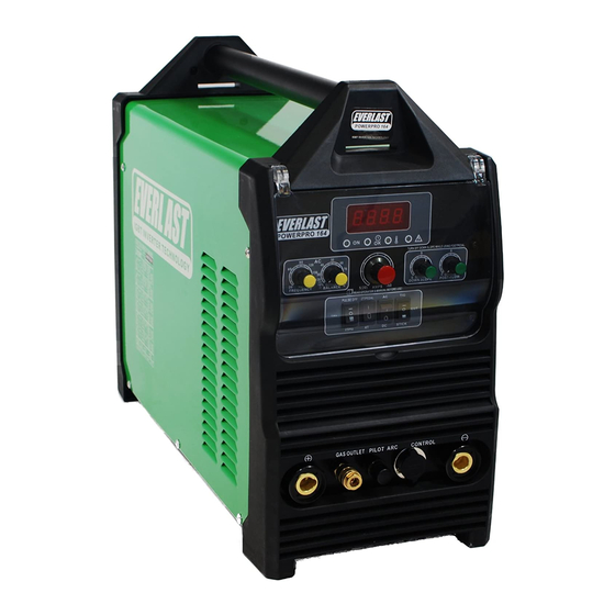
Operator's Manual for the PowerPro 164
Safety, Setup and General Use Guide
everlastwelders.com
POWERPRO 164
1-877-755-9353
329 Littlefield Ave. South San Francisco, CA 94080 USA
Rev. 2
Specifications and Accessories subject to change without notice.
0 00501-14
Advertisement
Table of Contents
Troubleshooting

Related Manuals for Everlast PowerPro 164


Summary of Contents for Everlast PowerPro 164
- Page 1 POWERPRO 164 GTAW-P SMAW IGBT PHASE AC/DC 120/240 Operator’s Manual for the PowerPro 164 Safety, Setup and General Use Guide Rev. 2 0 00501-14 everlastwelders.com Specifications and Accessories subject to change without notice. 1-877-755-9353 329 Littlefield Ave. South San Francisco, CA 94080 USA...
-
Page 2: Table Of Contents
The owner of this product assumes all liability for its use and maintenance. Everlast Power Equipment INC. does not warrant this product or this document for fitness for any particular purpose, for performance/accuracy or for suitability of application. -
Page 3: Letter To The Customer
Your unit registration is important should any information such as product updates or re- calls be issued. It is also important so that we may track your satisfaction with Everlast products and services. If you are unable to register by website, contact Everlast directly through the sales department through the main customer service number in your country. -
Page 4: Everlast Contact Information
Model number: ____________________________ Date of Purchase___________________________ EVERLAST Contact Information Everlast US: Everlast consumer satisfaction email: sales@everlastwelders.com Everlast Website: everlastwelders.com Everlast Technical Support: support@everlastwelders.com Everlast Support Forum: http://www.everlastgenerators.com/forums/index.php Main toll free number: 1-877-755 WELD (9353) 9am—5pm PST M-F 11am-4pm PST Sat. -
Page 5: Safety Precautions
Safe operation and proper maintenance is your responsibility. We have compiled this operator’s manual, to instruct you in basic safety, oper- ation and maintenance of your Everlast product to give you the best possible experience. Much of welding and cutting is based upon experience and com- mon sense. - Page 6 SAFETY PRECAUTIONS These safety precautions are for protection of safety and health. Failure to follow these guidelines may result in serious injury or death. Be careful to read and follow all cautions and warnings. Protect yourself and others. Welding and cutting processes produce high levels of ultraviolet (UV) radiation that can cause severe skin burn and damage.
- Page 7 SAFETY PRECAUTIONS WARNING! Persons with pacemakers should not weld, cut or be in the welding area until they consult with their physician. Some pacemakers are sensitive to EMF radiation and could severely malfunction while welding or while being in the vicinity of someone welding.
- Page 8 SAFETY PRECAUTIONS continued WARNING! Electrical shock can kill. Make sure all electrical equipment is properly grounded. Do not use frayed, cut or otherwise damaged cables and leads. Do not stand, lean or rest on ground clamp. Do not stand in water or damp areas while weld- ing or cutting.
-
Page 9: Introduction And Specifications
Foot Pedal Assembly NOTE: Accessory and consumable style and quantities are subject to change without notice. Consumable starter kits provide only enough consumables to get you started. Extra consum- ables can be purchased through Everlast or almost any local welding supply store. -
Page 10: Unit Specifications
Section 1 Introduction and Specifications PowerPro 164 SPECIFICATION Process AC/DC GTAW-P/DC SMAW/PAC Inverter Type Analog, Fairchild IGBT (non module) Minimum/Maximum Rated Output TIG 120/240v DC: 120 V: 5 A/10.2 V—25 A/ 15.0 V 240 V: 5 A/10.2 V — 60A/ 16.4 V AC: 120 V: 20 A/ 10.8V —... -
Page 11: General Overview
Duty Cycle. The duty cycle has been determined for the tends its capabilities. PowerPro 164 at 160 A @ 60% duty cycle for TIG and Stick. Improved HF point design offers better and more The duty cycle is based off a 10 minute duty cycle rating at stable arc starts, even at lower amperages. -
Page 12: Quick Setup Guide, Tig Torch/Cooler Connection
Section 2 QUICK SETUP AND USE GUIDE QUICK SETUP GUIDE: TIG CONNECTIONS TORCH (-) WORK (+) PILOT CONTROL 35 SERIES CONNECTOR 35 SERIES CONNECTOR AIR-COOLED TORCH GAS (Ar) 9/17 SERIES TORCH CONTROL CONTROL 26 SERIES TORCH FOOT PEDAL 35 SERIES CONNECTOR GAS (Ar) CONTROL NOTE: Torch switch and foot pedal... -
Page 13: Quick Setup Guide, Plasma Connection
When using lower amperage levels, the nozzles will need to be changed out for ones with a smaller diameter orifice. Everlast is the OEM supplier of the torch but not the manufacturer. Smaller diameter nozzles are available through Trafimet authorized distributors. -
Page 14: Quick Setup Guide, Stick Polarity And Connection
Section 2 QUICK SETUP AND USE GUIDE QUICK SETUP GUIDE: STICK POLARITY AND CONNECTIONS PILOT CONTROL TORCH (+) WORK (-) -
Page 15: Quick Setup Guide, Rear Connection For Plasma
Section 2 QUICK SETUP AND USE GUIDE QUICK SETUP GUIDE: REAR CONNECTIONS FOR PLASMA OPERATION Compressor and Dryer Diagram Compressor and Air hose w fittings (Customer Supplied) Regulator Assembly with built-in water trap and dirt filter (Included) CLAMP 1/4” Automotive Universal style quick connector (Included) 1~220 VAC Air Dryer/Oil Filter... -
Page 16: Quick Setup Guide, Rear Connection For Tig
SUPPLIED PLUG IS A NEMA 6-50P, THE STANDARD PLUG FOR MOST 1 PHASE 240 V WELDERS IN THE US AND CANADA. To convert to 120V operation, you may purchase a separate 240V to 120V adapter from Everlast. Rewiring the unit for strictly 120V operation by removing the existing plug is strongly discouraged. -
Page 17: Front Panel Features And Controls
Section 2 QUICK SETUP AND USE GUIDE FRONT PANEL FEATURES AND CONTROLS 17. PRESSURE GAUGE/REGULATOR (LOCATED ON REAR OF UNIT) 16. AMP DISPLAY 1. PROTECTIVE COVER 15. STATUS/WARNING INDICATORS 2. 2T/PEDAL/ OR 4T SWITCH 14. AMP CONTROL 13. POST FLOW 3. - Page 18 Section 2 QUICK SETUP AND USE GUIDE FRONT PANEL FEATURES AND CONTROLS CONTINUED POWERPRO 164 FEATURES PARAMETERS PURPOSE 1. Protective Cover Clear hinged cover protects panel from damage. Keep closed during welding operations. 2. 2T/4T Sequencer Switch 2T -Pedal/4T Used with the torch switch function. Select 2T for simple press and hold operation of the torch switch.
- Page 19 If the light does not go out after the cool down period by cycling the switch, or if comes on again when the arc is struck, contact Everlast. Over Current Indicator: Lights up when a voltage /amp surge has surpassed the units capabilities. Eliminate the source of the surge and manually cycle the power switch to reset.
-
Page 20: Rear Panel Features And Controls
Section 2 QUICK SETUP AND USE GUIDE REAR PANEL FEATURES AND CONTROLS 1. 2-POLE POWER SWITCH 5. REGULATOR ASSY. 1~220 VAC 2. POWER CABLE 1 ~ 220/240V 1~220 V INLET 4. HF GROUND BOLT 3. GAS INLET... - Page 21 Less than 5% is preferred. Operating the unit on square wave output or modified sine wave generator is strictly prohibited. Contact the manufacturer of the generator for this information. Everlast does not have an “approved” list of generators. But, if the generator is not listed as clean power by its manufacturer, then operation is prohibited.
-
Page 22: Welder Function Summary And Explanations
Section 3 Basic theory and function Welder Function Summary and Explanations. Post-Flow is a feature that works in conjunction with 1. 2T/4T sequencer. The 2T/4T feature allows op- both the foot pedal and the 2T/4T sequencer. Add eration of the TIG welder without a foot pedal. In more post flow time for larger welds. - Page 23 Section 3 Basic theory and function Cleaning/Frosted Area of Aluminum the side of the weld. Not all weld conditions will be alike, so more cleaning is required at times than 30% EP others. Similarly, more penetration will be re- Narrow bead/etching/sharp tungsten quired at times than others.
- Page 24 Pulse Amps deterioration or burn through. In effect you are cre- ating an average of amps. The PowerPRO 164 has Pulse Hz been created with a simple function pulse. The pulse frequency can be selected for either 1 Hz or 25 Hz.
- Page 25 Always set the panel amps to about 25% more than what is needed. In- Everlast. Do not use a nipple that is scarred, bent or other- wise deformed. Damage to the female connector may re-...
-
Page 26: Tungsten Preparation
Section 3 Basic theory and function TUNGSTEN PREPARATION 1. Use a dedicated grinding wheel or contamination may re- sult. Do not breath grinding dust! Wear eye protection and gloves. 2. Hold Tungsten firmly. 3. Grind perpendicular to grind- ing wheel face. -
Page 27: High Frequency Start Tig Operation
Section 3 Basic theory and function HIGH FREQUENCY START TIG OPERATION FOR AC OR DC USE. <1/8 <1/8” 1. Position the point of the sharpened tungsten about 1/8” or less above the metal. 2. Press the torch trigger or press the foot pedal to initiate the arc. The HF arc will be initiated. It may appear briefly as a blue spark. 3. - Page 28 Section 3 Basic theory and function STICK OPERATION STARTING METHODS Tapping Method Scratch/Match Method 1. Turn on the power switch on the rear of the unit. Allow unit to cycle through its start up program. 2. Select the Stick mode with the HF/Lift Start/Stick selector switch. 3.
-
Page 29: Plasma Function And Operation
Section 3 Basic theory and function The design of the blow back start may cause a slight delay in the arc as the air pressure must built inside the torch tubing and head to create the pressure needed to force the electrode off the nozzle seat. This may take up to two seconds. - Page 30 Section 3 Basic theory and function TIP: For longer consumable life do not use the pilot arc unnecessarily. FLAME AT NORMAL TRAVEL SPEED FLAME AT FAST TRAVEL SPEED TRAVEL TRAVEL FLAME AT SLOW TRAVEL SPEED 15-30 TRAVEL NOTE: When stepping down amps to cut thinner material, you must change to small- er orifice nozzle.
- Page 31 Section 3 Basic theory and function RESULTS OF CUT AT CORRECT SPEED, RESULTS OF CUT AT FAST SPEED AIR PRESSURE AND TORCH ANGLE ROUGH, DISTINCT CUT LINES SPACED FAR APART SMOOTH, EVEN CUT LINES WITH A S REARWARD SWEEP MINIMAL EASY TO CLEAN DROSS NOTICEABLE SMALL, HARD DROSS RESULTS OF TOO MUCH CURRENT OR RESULTS OF CUT AT SLOW SPEED...
- Page 32 Section 3 Basic theory and function AN EXAMPLE OF CUTTING A LEAD-IN WHEN CUTTING OUT A DISK SHAPED OBJECT AN EXAMPLE OF CUTTING A LEAD-IN WHEN CUTTING HOLE IN AN OBJECT When cutting an object, particularly a pattern shape, where the torch must pierce or re-fire in-line at an inter- section of a cut, a lead-in cut should be employed.
-
Page 33: Recommendations For Polarity/Amps/Tungsten
Section 3 Basic theory and function GENERAL POLARITY RECOMMENDATIONS* *Follow manufacturer of stick electrode for complete polarity recommendations PROCESS TORCH POLARITY WORK POLARITY TIG (GTAW) STICK (SMAW) TIG (GTAW) OPERATION GUIDE FOR STEEL (ALUMINUM)* *As a general rule, set amperage using 1 amp for every .001” of metal thickness for aluminum. Less is required for DC. METAL THICKNESS WELDING AMPS TUNGSTEN DIA. -
Page 34: Expanded View Of Tig Torch
Section 3 Basic theory and function EXPANDED VIEW OF TIG TORCH (Actual appearance may vary slightly from what is listed.) 5/8” Parts for Standard 17/26 Series Torch ( 18 series uses same consumables QTY. and basic design is similar, except water cooler line plumbing) Long Back Cap with O-Ring Short Back Cap Opt. -
Page 35: Powerpro 164 Plasma Torch S-45
POWERPRO 205 S-45 PLASMA TORCH** *Everlast is not the manufacturer of the Trafimet S-75 torch, nor is it affiliated with Trafimet other than its role as an OEM supplier of torches on PowerPRO S-Series units. Trafimet and its logo are a gistered trademarks of Trafimet. Not all items, accessories and parts depicted are available directly through Everlast. These are items supplied through nationwide Trafimet dealers and resalers. -
Page 36: Pin Connector Pin-Out
Section 3 Basic theory and function 7 PIN CONNECTOR FOR 47K Ω FOOT PEDAL Bridge to 7 To Pedal or Torch Switch Bridge to 6 To Pedal or Torch Switch... -
Page 37: Troubleshooting
Check gas flow. Adjust for higher flow of gas. Listen for audible click of gas solenoid. If no click is heard, then contact Everlast Support. Clean weld properly, especially in Aluminum. Too short of post flow. Check tungsten stick out. -
Page 38: Trouble Shooting
Make sure swirl ring is not cracked. Arc will try to start if touched to the metal, but no air Stuck or dirty solenoid valve. Contact Everlast. Wrong Pro- flow while switch is pressed. cess selected.
Need help?
Do you have a question about the PowerPro 164 and is the answer not in the manual?
Questions and answers