
Related Manuals for Mitsubishi AJ65BT-64DAV


Summary of Contents for Mitsubishi AJ65BT-64DAV
- Page 1 Digital-Analog Converter Module Type AJ65BT-64DAV/DAI User s Manual Mitsubishi Programmable Controller...
-
Page 3: Safety Precautions
• SAFETY PRECAUTIONS • (Read these precautions before using.) When using Mitsubishi equipment, thoroughly read this manual and the associated manuals introduced in this manual. Also pay careful attention to safety and handle the module properly. The precautions given in this manual are concerned with this product. Refer to the user's manual of the CPU module to use for a description of the PLC system safety precautions. -
Page 4: Wiring Precautions
[INSTALLATION PRECAUTIONS] CAUTION • Use the module in the environment given in the general specifications of this Manual. Using the module outside the range of the general specifications may result in electric shock, fire or malfunctioning, or may damage or degrade the module. •... - Page 5 [STARTING AND MAINTENANCE PRECAUTIONS] CAUTION • Do not touch the terminals while the power is on. Doing so may cause malfunctioning. • Be sure to shut off all phases of the external power supply used by the system before cleaning or retightening the terminal screws.
- Page 6 Japanese Manual Version SH-3600-H This manual does not imply guarantee or implementation right for industrial ownership or implementation of other rights. Mitsubishi Electric Corporation is not responsible for industrial ownership problems caused by use of the contents of this manual.
-
Page 7: Table Of Contents
Introduction Thank you for purchasing the Mitsubishi Graphic Operation Terminal. Before using the equipment, plese read this manual carefully to develop full familiarity with the functions and performance of the graphic operation terminal you have purchased, so as to ensure correct use. - Page 8 4.6.2 CC-Link dedicated cable connections ..................4- 6 4.7 Wiring................................ 4- 7 4.7.1 Precautions when wiring ....................... 4- 7 4.7.2 Wiring between the AJ65BT-64DAV/DAI and external devices ..........4- 7 5. PROGRAMMING 5- 1 to 5-16 5.1 Programming Procedure.......................... 5- 1 5.2 Conditions of Program Example......................
-
Page 9: About This Manual
Conformation to the EMC Directive and Low Voltage Instruction When complying with EMC Directives and Low-Voltage Directives by assembling a Mitsubishi PLC compatible with EMC Directive and Low-Voltage Directives into the user product, refer to Chapter 3 "EMC Directives and Low-Voltage Directives" in the User’s Manual (Hardware) for the CPU module being used. -
Page 10: Features
This is a module which converts the digital values (16-bit encoded binary value) set in the PLC CPU to analog values (4mA to 20mA current), and performs an external output to four channels. In this manual, the name which refers to both AJ65BT-64DAV and AJ65BT-64DAI is abbreviated as “AJ65BT-64DAV/DAI.”... - Page 11 1. OVERVIEW MELSEC-A MEMO...
-
Page 12: System Configuration
2. SYSTEM CONFIGURATION MELSEC-A SYSTEM CONFIGURATION (1) Applicable CPU When the master module is AJ61BT11: A0J2CPU A0J2HCPU A1CPU A2CPU(S1) A3CPU A1NCPU A2NCPU(S1) A3NCPU A3MCPU A3HCPU A2ACPU(S1) A3ACPU A2UCPU(S1) A3UCPU A4UCPU A73CPU A1SCPU(C24-R2) A1SJCPU A2SCPU A2USCPU(S1) Q02CPU-A Q02HCPU-A Q06HCPU-A A1SJHCPU A1SHCPU A2SHCPU (b) When the master module is AJ61QBT11: Q2ACPU(S1) - Page 13 2. SYSTEM CONFIGURATION MELSEC-A MEMO...
-
Page 14: Specifications
3. SPECIFICATIONS MELSEC-A SPECIFICATIONS The general specifications, performance specifications, and I/O characteristics of the AJ65BT-64DAV/DAI are explained. General Specification The general specifications of the AJ65BT-64DAV/DAI are shown in Table 3.1. Table 3.1 General specification Item Specification Usage ambient 0 to 55°C... -
Page 15: Performance Specification
3. SPECIFICATIONS MELSEC-A Performance Specification The performance specification of the AJ65BT-64DAV/DAI is shown Table 3.2: Table 3.2 Performance specification Specification Item AJ65BT-64DAV AJ65BT-64DAI 16-bit encoded binary (valid bit: 12 bits) Digital input value -2048 to 2047 0 to 4095 Voltage: -10 to 10VDC... - Page 16 3. SPECIFICATIONS MELSEC-A Maximum resolution of analog value The maximum resolution of analog value means the variation of analog value when the digital value changes for "1". Total accuracy The total accuracy is the accuracy of the maximum analog output value. The overall accuracy of the AJ65BT-64 DAV is the accuracy for 10V.
-
Page 17: I/O Conversion Characteristics
3.3.1 Offset value and gain value (1) Offset value This is an analog value (voltage or current value) produced by the AJ65BT-64DAV/DAI when the digital value set by the PLC CPU is "0". (2) Gain value This is an analog value (voltage or current value) produced by the AJ65BT-64DAV/DAI when the digital value set by the PLC CPU is "2000"... - Page 18 The analog output voltage for the characteristic graphs becomes as below, when the digital input value is at 1000 and 500: Number Digital input value Analog output voltage 1000 +5.0V +2.5V 1000 -5.0V 1000 +6.0V +5.0V Figure 3.2 I/O conversion characteristics of AJ65BT-64DAV...
- Page 19 3. SPECIFICATIONS MELSEC-A (2) When AJ65BT-64DAI is used: Gain value Offset value (mA) Analog output practical range 4000 4095 Digital input value Figure 3.3 I/O conversion characteristics of AJ65BT-64DAI How to calculate the analog value The resolution of AJ65BT-64DAI can be set arbitrarily by modifying the settings of the offset value and gain value.
- Page 20 3. SPECIFICATIONS MELSEC-A The following graph shows the I/O characteristic when the offset and gain values of the AJ65BT-64DAI are changed: The I/O conversion characteristics are shown in the graph on the right when the offset value and the gain value are set as in the following table: (mA) Number Offset value...
-
Page 21: Various Functions To Control The Analog Output
(i.e. to output the offset) the analog output value immediately before the PLC CPU enters the STOP status or before the AJ65BT-64DAV/DAI stops the D/A conversion due to an error. All channels are set simultaneously. (Including a time when link communications are shut off) 3.4.2... - Page 22 AJ65BT-64DAV/DAI analog value analog value Analog output status when a WDT error (*) has 0V/0mA occurred in the AJ65BT-64DAV/DAI Analog value Analog output status when the L.RUN LED is before the turned off (when link communications are shut...
-
Page 23: I/O Signals To The Master Station
The allocation of the I/O signals and the name of each signal are listed in Table 3.4. An RX device indicates an input signal from the AJ65BT-64DAV/DAI to the master module, and a RY device indicates an output signal from the master module to the AJ65BT-64DAV/DAI. -
Page 24: Functions Of The I/O Signals
3. SPECIFICATIONS MELSEC-A 3.5.2 Functions of the I/O signals Functions of the I/O signals of the AJ65BT-64DAV/DAI are shown in Table 3.5. Table 3.5 Descriptions of the I/O signals Device number Signal Name Description After the power is turned on or after the hardware reset, the initial data... -
Page 25: Remote Register
3. SPECIFICATIONS MELSEC-A Remote Register The AJ65BT-64DAV/DAI has a remote register (does not have backup) for data communication with the master module. The remote register allocation and data structure are described below. 3.6.1 Allocation of the remote register The allocation of the remote register is shown in Table 3.6. -
Page 26: Digital Value Setting Area For Channels 1 Through 4
Digital value for the D/A conversion Model Name Available setting range when the value beyond the range is set -2048 to 2047 2048 or higher: 2047 AJ65BT-64DAV (Practical range: -2000 to 2000) -2049 or lower: -2048 0 to 4095 4096 or higher: 4095 AJ65BT-64DAI... -
Page 27: Set Value Checking Code Storage Area For Channels 1 Through 4
(RY (n+1) A). 3.6.5 Error code (1) If an error occurs when starting the module or writing data to the AJ65BT-64DAV/DAI (the RUN LED flashes), the following error code is stored in the error code (RWrn+4) in the AJ65BT-64DAV/DAI remote register. -
Page 28: Setup And Preparation Before Operation
MELSEC-A SETUP AND PREPARATION BEFORE OPERATION Precautions When Handling The precautions when handling the AJ65BT-64DAV/DAI are described below: Do not touch the terminals while the power is on. CAUTION Doing so may cause malfunctioning. Be careful not to let foreign matter such as filings or wire chips get inside the module. -
Page 29: Name Of Each Part
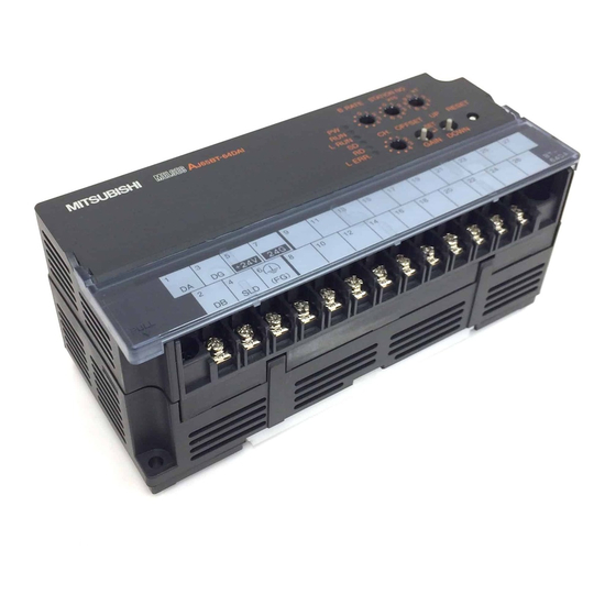
4. SETUP AND PREPARATION BEFORE OPERATION MELSEC-A Name of Each Part The name of each part in the AJ65BT-64DAV/DAI is described. B RATE STATION NO. MITSUBISHI MELSEC AJ65BT-64DA L RUN OFFSET GAIN. RESET L ERR. GAIN DOWN Number Name Description ↓... - Page 30 Flashing at irregular intervals : When you forgot fitting the termination resistors or the module or CC-Link dedicated cable is affected by noise. : Normal communication Terminal block AJ65BT-64DAV HLD/ HLD/ CH1/ +24V +24V (FG)
-
Page 31: Offset/Gain Setting
4. SETUP AND PREPARATION BEFORE OPERATION MELSEC-A Offset/Gain Setting When changing the I/O conversion characteristics, follow the procedure below. Start Voltage Current Set to the voltage the offset Set to the current the offset Short the test mode terminal value using the "UP/DOWN value using the "UP/DOWN (between 8 to 10). -
Page 32: Station Number Setting
Point (1) Set the offset and gain values in the actual usage state. (2) The offset and gain values are stored in the AJ65BT-64DAV/DAI, and are not erased even the power supply is shut off. (3) Perform the offset/gain setting when the PLC CPU is stopped. -
Page 33: Data Link Cable Wiring
4. SETUP AND PREPARATION BEFORE OPERATION MELSEC-A Data link Cable Wiring The wiring of the CC-Link dedicated cable which connects the AJ65BT-64DAV/DAI and the master module is described. 4.6.1 Precautions when handling the twisted pair cable Do not handle the CC-Link dedicated cable in extreme ways as bellow, for the cable may be damaged: (1) Compact with a sharp object (2) Twist the cable excessively. -
Page 34: Wiring
The precautions performing external wiring for the AJ65BT-64DAV/DAI are shown below: (1) Use separate cables for the AC and AJ65BT-64DAV/DAI external input signals, in order not to be affected by the AC side surge or conductivity. - Page 35 4. SETUP AND PREPARATION BEFORE OPERATION MELSEC-A (2) Wiring example of the AJ65BT-64DAI and external devices is shown in Figure 4.2. AJ65BT-64DAI Motor drive module, etc. CH.1 Motor drive module, etc. CH.4 *1 Use a two-core twist shielded line for the wiring. *2 When noise or ripple generates within the external wiring, connect a condenser with about 0.1 to 0.47μF (25V or higher voltage-resistant product) to the input terminal of the external device.
-
Page 36: Programming
Refer to the user's manual of the master module used for the master module, to Section 3.6 for the remote registers, and to the AnSHCPU/AnACPU/AnUCPU/QCPU (A mode) Programming Manual (Dedicated Instructions) for details of the dedicated instructions. Programming Procedure Create programs for executing the digital-analog conversion of the AJ65BT-64DAV/DAI in the following procedure. Start Select factory-set/user-set... -
Page 37: Conditions Of Program Example
ACPU/QCPU (A mode), RWr0 to RWr3 are assigned to D456 to D459. * 2 Although RX20 to RX3F and RY20 to RY3F are not used in the AJ65BT-64DAV, devices for them are reserved in a master module or CPU module. - Page 38 5. PROGRAMMING MELSEC-A POINT Some CPU modules may not accept the devices used in the program example in this chapter. For the setting ranges of the devices, refer to the user's manual of the CPU module used. For the A1SHCPU, for example, devices X100, Y100 and later are unusable. Use such devices as B and M.
-
Page 39: Program Example For Use Of The Qcpu (Q Mode)
5. PROGRAMMING MELSEC-A Program Example for Use of the QCPU (Q mode) The program examples in this section are created under the following conditions. GX Developer is used to set the network and automatic refresh parameters. Using the remote device station initialization procedure registration function facilitates initial settings. (1) Parameter setting (a) Network parameter setting (b) Automatic refresh parameter setting... - Page 40 (b) Setting the procedure registration When the initial data processing request flag (RX18) turns on and the remote device station initialization procedure registration (SB0D) is set, the following data are registered to the AJ65BT-64DAV. Procedure Execution Condition Execution Offset/gain value selection (RY04) is turned on (factory setting).
- Page 41 5. PROGRAMMING MELSEC-A (3) Program example *Checking of AJ65BT-64DAV status Reads data link status AJ65BT-64DAV data link normal AJ65BT-64DAV data link normal *Initial settings Offset/gain value selection (RY04) Analog output enable/ disable setting (RWw4) Turns on initial data procedure completion flag (RY18)
- Page 42 5. PROGRAMMING MELSEC-A (4) Program example *Checking of AJ65BT-64DAV status Reads data link status AJ65BT-64DAV data link normal AJ65BT-64DAV data link abnormal *Initialization procedure registration Turns off initialization procedure registration directive Turns on initialization procedure registration directive *Changing of Initial settings...
- Page 43 5. PROGRAMMING MELSEC-A *1 When remote device station initialization procedure registration is to be made to multiple modules, correct the program part enclosed by the dotted line 1) as shown below. RX(m+1)B/RX(n+1)B indicates remote READY, and RX(m+1)8/RX(n+1)8 indicates an initial data processing request flag.
-
Page 44: Program Example For Use Of The Qnacpu
5. PROGRAMMING MELSEC-A Program Example for Use of the QnACPU GX Developer is used to set the network and automatic refresh parameters. (1) Parameter setting (a) Network parameter setting (b) Automatic refresh parameter setting POINT When the QnACPU is used, using "Y" as the remote output (RY) refresh device of the automatic refresh parameter may not hold the analog value even for the HOLD setting. -
Page 45: Program Example For Use Of The Acpu/Qcpu (A Mode) (Dedicated Instructions)
A sequence program is used to set the network and automatic refresh parameters. (1) Program example *Setting of network parameters using RLPA dedicated instruction Synchronization mode: invalid Number of connected modules:1 AJ65BT-64DAV station information (remote device station, 2 stations occupied, station No.1) Dedicated instruction (RLPA) Starting I/O number of... - Page 46 5. PROGRAMMING MELSEC-A Sets RX starting number Sets "X" Sets X400 Sets 32points Sets RY starting number Sets "Y" Sets Y400 Sets 32points Sets RW starting number Sets "D" Sets D200 Sets 264points Sets SB starting number Sets "B" Sets B0 Sets 512points Sets SW starting number Sets "W"...
- Page 47 5. PROGRAMMING MELSEC-A *Checking of AJ65BT-64DAV status Reads data link status AJ65BT-64DAV data link normal AJ65BT-64DAV data link abnormal *Initial settings Offset/gain value selection (RY04) Analog output enable/ disable setting (RWw4) Turns on initial data processing completion flag (RY18) Turns on initial data setting...
- Page 48 5. PROGRAMMING MELSEC-A *Processing at error occurence Reads CH. Check code (RWr0, RWr1, RWr2, RWr3) Reads error code(RWr4) Error reset Turns on error reset request flag (RY1A) Turns off error reset request flag (RY1A) 5-13...
-
Page 49: Program Example For Use Of The Acpu/Qcpu (A Mode) (From/To Instructions)
Turns off start request signal at abnormal completion of start *Read of remote input signals RX00 to RX1F are read to X400 to X41F *Checking of AJ65BT-64DAV status Reads data link status AJ65BT-64DAV data link normal AJ65BT-64DAV data link abnormal... - Page 50 5. PROGRAMMING MELSEC-A *Initial settings Offset/gain value selection (RY04) Analog output enable/disable setting (RWw4) Writes to the master station Turns on initial data procedure completion flag (RY18) Turns on initial data setting request flag (RY19) *Changing of Initial settings Initial setting change Offset/gain value selection (RY04) Analog output enable/...
- Page 51 5. PROGRAMMING MELSEC-A *Processing at error occurence Read CH. Check code (RWr0, RWr1, RWr2, RWr3) Read error code (RWr4) Error reset Turns on error reset request flag (RY1A) Turns off error reset request flag (RY1A) 5-16...
-
Page 52: Troubleshooting
Error Code List When the data is written from the PLC CPU to the master module, and an error occurs (AJ65BT-64DAV/DAI RUN LED flashes), the error code is stored to the AJ65BT-64DAV/DAI remote register RWrn+4. Refer to Section 3.6.5 for the error code. -
Page 53: When A Communication Fault Occurs Between The Master Station And This Module
If the station-number-overlapping bit is turned on in the link special resister SW0098 to SW009B (station number overlapping status), check the AJ65BT-64DAV/DAI module of the corresponding station number by following the flow shown below: Troubleshooting flow when the ERR LED on the master station is flashing "ERR"... -
Page 54: Appendix
APPENDIX MELSEC-A APPENDIX Appendix 1 External Dimensions of the AJ65BT-64DAV 4.5 (0.18) Installation hole B RATE STATION NO. MITSUBISHI MELSEC AJ65BT-64DAV L RUN OFFSET RESET L ERR. GAIN. DOWN 143 (5.63) 151.9 (5.98) Unit: mm (inch) App-1... -
Page 55: Appendix 2 External Dimensions Of The Aj65Bt-64Dai
APPENDIX MELSEC-A Appendix 2 External Dimensions of the AJ65BT-64DAI 4.5 (0.18) Installation hole B RATE STATION NO. MITSUBISHI MELSEC AJ65BT-64DAI L RUN OFFSET RESET L ERR. GAIN. DOWN 143 (5.63) 151.9 (5.98) Unit: mm (inch) App-2... - Page 56 APPENDIX MELSEC-A MEMO App-3...
- Page 57 APPENDIX MELSEC-A MEMO App-4...
- Page 58 6. Failure caused by reasons unpredictable by scientific technology standards at time of shipment from Mitsubishi. 7. Any other failure found not to be the responsibility of Mitsubishi or that admitted not to be so by the user. 2. Onerous repair term after discontinuation of production (1) Mitsubishi shall accept onerous product repairs for seven (7) years after production of the product is discontinued.
- Page 60 Digital-Analog Converter Module Type AJ65BT-64DAV/DAI User s Manual AJ65BT-64DA-U-S-E MODEL MODEL 13J895 CODE SH(NA)-3615-F(0612)MEE HEAD OFFICE : TOKYO BUILDING, 2-7-3 MARUNOUCHI, CHIYODA-KU, TOKYO 100-8310, JAPAN NAGOYA WORKS : 1-14 , YADA-MINAMI 5-CHOME , HIGASHI-KU, NAGOYA , JAPAN When exported from Japan, this manual does not require application to the Ministry of Economy, Trade and Industry for service transaction permission.
Need help?
Do you have a question about the AJ65BT-64DAV and is the answer not in the manual?
Questions and answers
data write error
A data write error in the Mitsubishi AJ65BT-64DAV is caused when a digital value written to the module is outside the valid setting range. This includes values that exceed or fall short of the allowed range. The module stores an error code (11) indicating the channel with the error. The error is not cleared even if a valid value is later written, unless the error reset request flag (RY(n+1)A) is turned on.
This answer is automatically generated