Advertisement
Quick Links
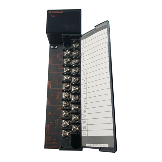
Converter Module
Thank you for purchasing the Mitsubishi programmable controller
MELSEC-A Series.
Prior to use, please read both this manual and detailed manual
thoroughly to fully understand the product.
© 2008 MITSUBISHI ELECTRIC CORPORATION
Analog-Digital
Model
MODEL
CODE
IB(NA)-0800371-C(1112)MEE
User's Manual
(Hardware)
A1S68AD
A1S68AD-U-HW
13JY17
Advertisement

Related Manuals for Mitsubishi MELSEC-A A1S68AD


Summary of Contents for Mitsubishi MELSEC-A A1S68AD
- Page 1 Analog-Digital Converter Module User's Manual (Hardware) A1S68AD Thank you for purchasing the Mitsubishi programmable controller MELSEC-A Series. Prior to use, please read both this manual and detailed manual thoroughly to fully understand the product. Model A1S68AD-U-HW MODEL 13JY17 CODE IB(NA)-0800371-C(1112)MEE...
- Page 2 SAFETY PRECAUTIONS (Always read before starting use) When using Mitsubishi equipment, thoroughly read this manual and the associated manuals introduced in the manual. Also pay careful attention to safety and handle the module properly. The instructions given this manual are concerned with this product. Refer to the User’s Manual of the CPU module in use for details on the safety instructions for...
- Page 3 [INSTALLATION PRECAUTIONS] CAUTION Use the programmable controller in an environment that meets the general specifications in the user's manual for the CPU module used. Failure to do so may cause an electric shock, fire, malfunction, or damage to or deterioration of the product. Insert the tabs at the bottom of the module into the holes in the base module before installing module.
- Page 4 [STARTING AND MAINTENANCE PRECAUTIONS] WARNING Do not touch the terminals while they are live. This will cause malfunctions. Make sure to switch all phases of the external power supply off before cleaning or re-tightening the terminal screws. Failure to do so will cause failure or malfunction of the module.
- Page 5 CONDITIONS OF USE FOR THE PRODUCT (1) Mitsubishi C Controller system ("the PRODUCT") shall be used in conditions; i) where any problem, fault or failure occurring in the PRODUCT, if any, shall not lead to any major or serious accident; and...
- Page 6 PRODUCT in one or more of the Prohibited Applications, provided that the usage of the PRODUCT is limited only for the specific applications agreed to by Mitsubishi and provided further that no special quality assurance or fail-safe, redundant or other safety features which exceed the general specifications of the PRODUCTs are required.
- Page 7 PRODUCT This manual confers no industrial property rights or any rights of any other kind, nor does it confer any patent licenses. Mitsubishi electric Corporation cannot be held responsible for any problems involving industrial property rights which may occur as a result of using the contents noted in this manual.
-
Page 8: Table Of Contents
CONTENTS 1. General Description ..................1 2. Performance Specifications ................2 3. Nomenclature and Settings ................4 4. Caution on Handling ..................7 5. Wiring ......................8 5.1 Cautions on Wiring .................. 8 5.2 Module connection example ..............9 6. Outside Dimensions ..................11... - Page 9 COMPLIANCE WITH EMC AND LOW VOLTAGE DIRECTIVES (1) Method of ensuring compliance To ensure that Mitsubishi programmable controllers maintain EMC and Low Voltage Directives when incorporated into other machinery or equipment, certain measures may be necessary. Please refer to one of the following manuals.
-
Page 10: General Description
1. General Description This manual provides the specifications and part names of the analog-digital converter module type A1S68AD (hereinafter referred to as "A1S68AD"), which is designed to use with the MELSEC-A series CPU module. -
Page 11: Performance Specifications
2. Performance Specifications The following table shows the performance specifications of the A1S68AD. Item Specification Voltage:-10 to 0 to +10 VDC (input resistance : 1M or more) Analog input Current:0 to +20mA (input resistance : 250 ) 16-bit signed binary Digital output Analog input value Digital output value... - Page 12 POINT The overall accuracy is applicable to the following analog input ranges: Voltage: -10 to 0 to +10V Current: 0 to +20mA Refer to the user's manual for the CPU module in use for details on the general specifications.
-
Page 13: Nomenclature And Settings
3. Nomenclature and Settings The following gives the Names and settings of each section for each part of the A1S68AD In this manual, modules whose hardware versions V or later are used for description. For the names and settings for each part of modules whose hardware version U or earlier, refer to the Analog-Digital Converter Module type A1S68AD User's Manual (IB-66576). - Page 14 No. Name and appearance Description “RUN” LED Displays the operating status of the A1S68AD. :Normal operation. Flash :Write disabled error or average time/count setting error. :5 V power cut or watchdog timer error. Input range selector Used to set the input range of each channel. switch SW1 (Factory default: 0 to 10V) The DIP switch numbers 1-8 correspond to the channel numbers.
- Page 15 Caution If voltage input appears when a current input range is selected, a failure may occur.
-
Page 16: Caution On Handling
4. Caution on Handling (1) The module case and the terminal block are made of resin. Do not drop the module or subject it to shock. (2) Do not remove the printed circuit board from the module case. This could cause failure. (3) During wiring, take all possible measures to prevent wire scraps or foreign matter from entering the module. -
Page 17: Wiring
5. Wiring This section gives the cautions on wiring and connection example for the module. 5.1 Cautions on Wiring To establish a highly reliable system by making the best use of the A1S68AD functions, external wiring that is not susceptible to the effects of noise is required. -
Page 18: Module Connection Example
5.2 Module connection example The figure below shows an example of voltage input and current input connections. (1) Voltage input connection Signal source 0 to 10V or more or more *1 Shield wire (2) Current input Signal source:0 to +20mA or more or more *1 Shield wire... - Page 19 *4: AG is the GND terminal of the analog circuit. Connecting it to the GND terminal of an external device is not mandatory, but a higher level of accuracy may be obtained when it is connected. If there are three or more channels of the input range of -10 to 10V and the external devices connected to the channels shares a common line, the AG terminal must be connected the shared common line of the external device.
-
Page 20: Outside Dimensions
6. Outside Dimensions 1S68AD 93.6 (3.69) 34.5 (1.36) (0.26) Unit:mm(inch) - Page 21 MEMO...
- Page 22 WARRANTY Mitsubishi will not be held liable for damage caused by factors found not to be the cause of Mitsubishi; machine damage or lost profits caused by faults in the Mitsubishi products; damage, secondary damage, accident compensation caused by special factors unpredictable by Mitsubishi;...
Need help?
Do you have a question about the MELSEC-A A1S68AD and is the answer not in the manual?
Questions and answers