Table of Contents
Advertisement
Quick Links
PL
AUTOMATYCZNY PRZEŁĄCZNIK AUTOMATIC TRANSFER
SZR
ATL10
● Przed pracami serwisowymi, należy odłączyć wszystkie napięcia
od wejść pomiarowych i zasilania pomocniczego oraz zewrzeć
zaciski przekładnika prądowego.
● Produkty zaprezentowane w poniższym dokumencie mogą zostać
zmienione lub ulepszone bez konieczności wcześniejszego
informowania o tym.
● Dane techniczne oraz opisy oddają w jak najdokładniejszy sposób
posiadaną przez nas wiedzę, jednak nie bierzemy
odpowiedzialności za ewentualne błędy, braki oraz sytuacje
awaryjne.
● W układzie należy zamontować rozłącznik (wyłącznik), który musi
znajdować się niedaleko urządzenia i być łatwo dostępny dla
operatora. Musi spełniać wymogi następujących norm: IEC/ EN
61010-1 § 6.12.2.1.
● Należy czyścić urządzenie delikatną suchą szmatką, nie należy
używać środków ściernych, płynnych detergentów
lub rozpuszczalników
SPIS TREŚCI
PANEL PRZEDNI ............... ............... ............... .............. 3
WYBÓR POMIARÓW ........... ............... ............... .............. 3
DIODY STATUSU ............... ............... ............... .............. 3
WYBÓR TRYBU PRACY . ... .............. ............... .............. 4
TRYB OFF-RESET .............. ............... ............... .............. 4
SYMULACJA ZANIKU LINII GŁÓWNEJ.......... .... .............. 5
APLIKACJA SIEĆ-GENERATOR ........ ............... .............. 5
APLIKACJA SIEĆ-SIEĆ ...... .............. ............... .............. 5
KONTROLA URZĄDZEŃ WYKONAWCZYCH .... .............. 6
STEROWANIE WYŁĄCZNIKAMI Z NAPĘDEM ... .............. 6
STEROWANIE ROZŁĄCZNIKAMI Z NAPĘDEM . .............. 6
STEROWANIE STYCZNIKAMI ............ ............... .............. 6
KONTROLA NAPIĘCIA ........ ............... ............... .............. 7
ALARMY............................. ............... ............... .............. 8
USTAWIANIE PARAMETRÓW (SETUP) ............ .............. 9
TABELA MENU ..... .............. ............... ............... .............. 9
MENU P1 - DANE ZNAMIONOWE ..... ............... .............. 9
MENU P2 - DANE OGÓLNE.. ............. ............... .............. 10
MENU P3 - KONTROLA NAPIĘCIA LINII 1 ........ .............. 12
MENU P4 - KONTROLA NAPIĘCIA LINII 2 ........ .............. 13
MENU P5 - WEJŚCIA PROGRAMOWALNE ...... .............. 14
MENU P6 - WYJŚCIA PROGRAMOWALNE ...... .............. 15
MENU P7 - KOMUNIKACJA................. .............. .............. 16
MENU A - ALARMY ........... ............... ............... .............. 17
WIADOMOŚCI DIAGNOSTYCZNE ..... ............... .............. 18
BLOKADA KLAWIATURY .... ............... ............... .............. 18
ZDALNA KONTROLA ........... ............... ............... .............. 18
MENU KOMEND ............... ............ ............... .............. 18
PODŁĄCZENIE ZACISKÓW .............. ............... .............. 19
WYMIARY MECHANICZNE I WYCIĘCIE W PANELU ....... 19
DANE TECHNICZNE............. .............. ............... .............. 22
Doc: MHIT100A0309_ATL10
UWAGA!
● Należy dokładnie zapoznać się z poniższa instrukcją
przed instalacją lub używaniem urządzenia.
● By uniknąć uszkodzeń i zagrożenia życia urządzenia
te powinny być instalowane przez wykwalifikowany
personel, i w zgodzie z odpowiednimi przepisami.
............... ............... ............... .............. 2
............... ............... ............... .............. 2
............... ............... ............... .............. 2
............... ............... ............... .............. 4
............... ............... ............... .............. 4
............... ............... ............... .............. 5
.. ............. ............... .............. 20
10/11/2009
SWITCH CONTROLLER
ATL10
WARNING!
●Carefully read the manual before the
installation or use.
●This equipment is to be installed by qualified
personnel, complying to current standards, to
avoid damages or safety hazards
●
Before any maintenance operation on the device, remove all the
voltages from measuring and supply inputs and short-circuit the CT
input terminals.
●
Products illustrated herein are subject to alteration and changes
without prior notice.
●Technical data and descriptions in the documentation are
accurate, to the best of our knowledge, but no liabilities for errors,
omissions or contingencies arising there from are accepted.
●A circuit breaker must be included in the electrical installation of
the building. It must be installed close by the equipment and within
easy reach of the operator. It must be marked as the disconnecting
device of the equipment: IEC /EN 61010-1 § 6.12.2.1.
●Clean the instrument with a soft dry cloth; do not use abrasives,
liquid
INDICE
.............. ............... ............... ............... 2
.............. ............... ............... ............... 2
.............. ............... ............... ............... 2
.............. ............... ............... ............... 3
MEASURE SELECTION ..... ............... ............... ............... 3
.............. ............... ............... ............... 3
OPERATING MODE SELECTION ....... ............... ............... 4
OFF-RESET MODE ............. ............... ............... ............... 4
.............. ............... ............... ............... 4
.............. ............... ............... ............... 4
MAIN LINE FAILURE SIMULATION .... ............... ............... 5
UTILITY-TO-GENERATOR APPLICATION ......... ............... 5
UTILITY-TO-UTILITY APPLICATION .. ............... ............... 5
.............. ............... ............... ............... 5
CONTROL OF CHANGEOVER DEVICES .......... ............... 6
CONTROL OF MOTORISED CIRCUIT BREAKERS .......... 6
CONTROL OF MOTORISED CH./OVER SWITCHES ....... 6
CONTROL OF CONTACTORS .......... ............... ............... 6
VOLTAGE CONTROLS ....... ............... ............... ............... 7
ALARMS.............. .............. ............... ............... ............... 8
PARAMETERS SETUP ........ ............... ............... ............... 9
.............. ............... ............... ............... 9
MENU P1 - RATINGS ......... ............... ............... ............... 9
MENU P2 - GENERAL DATA ............. ............... ............... 10
MENU P3 - LINE 1 VOLTAGE CONTROL ......... ............... 12
MENU P4 - LINE 2 VOLTAGE CONTROL ......... ............... 13
MENU P5 - PROGRAMMABLE INPUTS ............ ............... 14
MENU P6 - PROGRAMMABLE OUTPUTS ........ ............... 15
MENU P7 - SERIAL COMMUNICATION ............ ............... 16
MENU A - ALARMS ........... ............... ............... ............... 17
DIAGNOSTIC MESSAGES .. ............... ............... ............... 18
.............. ............... ............... ............... 18
REMOTE CONTROL ........... ............... ............... ............... 18
COMMAND MENU.. ............. ............... ............... ............... 18
REAR TERMINAL CONNECTIONS .... ............... ............... 19
MECHANICAL DIMENSIONS AND PANEL CUT-OUT ....... 19
WIRING DIAGRAMS ............ ............... ............... ............... 20
TECHNICAL CHARACTERISTICS ...... ............... ............... 22
.
s. 1 / 22
Advertisement
Table of Contents

Related Manuals for LOVATO ELECTRIC ATL10


Summary of Contents for LOVATO ELECTRIC ATL10
-
Page 1: Table Of Contents
AUTOMATYCZNY PRZEŁĄCZNIK AUTOMATIC TRANSFER SWITCH CONTROLLER ATL10 ATL10 UWAGA! ● Należy dokładnie zapoznać się z poniższa instrukcją WARNING! ●Carefully read the manual before the przed instalacją lub używaniem urządzenia. installation or use. ● By uniknąć uszkodzeń i zagrożenia życia urządzenia ●This equipment is to be installed by qualified... -
Page 2: Opis
OPIS DESCRIPTION Mikroprocesorowy automatyczny przełącznik SZR. Microprocessor-based automatic transfer switch controller Dwa wejścia do pomiaru napięcia Two voltage measuring inputs for three-phase + neutral trójfazowego+przewód neutralny Zasilanie DC 12-24-48 V 12-24-48 VDC power supply ... -
Page 3: Panel Przedni
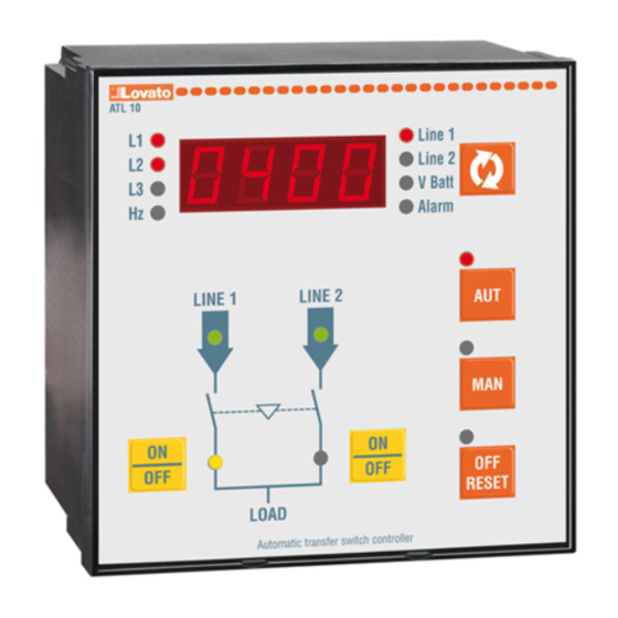
PANEL PRZEDNI FRONT PANEL Panel przedni wyposażony jest w wyświetlacz LED, The unit front panel is equipped with a LED display który pokazuje mierzone napiecia dwóch linii (Linia 1 which shows the voltages of the two supply lines (Line 1 i Linia 2), wyboru dokonujemy przyciskiem (A) and Line 2) with the relevant key for measure selection ... -
Page 4: Wybór Trybu Pracy
WYBÓR TRYBU PRACY OPERATING MODE SELECTION Trzy przyciski funkcyjne OFF-RESET / MAN / AUT The three keys OFF-RESET / MAN / AUT allow to pozwalają na wybór wymaganego trybu pracy, który select the required operating mode, which will be będzie sygnalizowany odpowiednia czerwoną... -
Page 5: Symulacja Zaniku Linii Głównej
P2.14 to allow it to cool down w parametrze P2.14. Przełącznik ATL10 wysyła komendę The ATL10 switch sends a start/stop command to the rozruchu/zatrzymania do generatora poprzez wyjście generator through a relay output and can receive przekaźnikowe i może otrzymać... -
Page 6: Kontrola Urządzeń Wykonawczych
Jeśli wejścia statusu urządzenia nie są używane, If the device status inputs are not used, then ATL10, ATL10 po włączeniu zasilania, wysyła komendę after power-on, sends an open command to bring the otwarcia i trzyma urządzenia wykonawcze... -
Page 7: Kontrola Napięcia
KONTROLA NAPIĘCIA VOLTAGE CONTROLS All the conditions which can help establish whether a Wszystkie warunki które, pozwalają ustalić czy źródło zasilania jest odpowiednie czy nie, są zdefiniowane power source is or is not suitable are defined by the przez użytkownika poprzez menu P1 (zakresy) user through menu P1 (ratings) and menus P3 and P4 i menu P3 i P4 (limity napięcia linii 1 i linii 2). -
Page 8: Alarmy
ALARMY ALARMS Kiedy pojawia sie sytuacja alarmowa, ATL10 When an alarm situation occurs, ATL10 either shows a wyświetla na wyświetlaczu kod alarmu lub świeci code on the displays or lights up a dedicated LED się odpowiednia dioda LED ... -
Page 9: Ustawianie Parametrów (Setup)
USTAWIANIE PARAMETRÓW (SETUP) PARAMETERS SETUP By uzyskać dostęp do ustawień parametrów, należy To access parameter setup, starting with the unit in OFF- ustawić jednostkę w tryb OFF-RESET, wcisnąć RESET mode, press the A and D keys together for five jednocześnie przyciski A i D i przytrzymać... -
Page 10: Menu P2 - Dane Ogólne
MENU P2 – DANE OGÓLNE MENU P2 –GENERAL DATA Funkcja Zakres Domyś. Function Range Default P2.01 Typ aplikacji U-G = Sieć- P2.01 Type of application U-G = Utility to Generator Generator U-U = Sieć – Sieć U-U = Utility to Utility P2.02 Kontrola kolejności OFF –... - Page 11 ATL10 jest w trybie RESET/OFF. Ten parametr może ATL10 is in RESET/OFF mode. This parameter can be useful być użyteczny kiedy mamy aplikację wykonaną na when working with contactors.
-
Page 12: Menu P3 - Kontrola Napięcia Linii 1
MENU P3 – KONTROLA NAPIĘCIA LINII 1 MENU P3 – LINE 1 VOLTAGE CONTROL Funkcja Zakres Domyś. Function Range Default P3.01 Próg zadziałania dla 70…98 % P3.01 Minimum voltage 70…98 % napięcia minimalnego threshold – trip P3.02 Próg powrotu dla 75…100 % P3.02 Minimum voltage 75…100 %... -
Page 13: Menu P4 - Kontrola Napięcia Linii 2
MENU P4 – KONTROLA NAPIĘCIA LINII 2 MENU P4 – LINE 2 VOLTAGE CONTROL Funkcja Zakres Domyś. Function Range Default P4.01 Próg zadziałania dla 70…98 % P4.01 Minimum voltage 70…98 % napięcia minimalnego threshold – trip P4.02 Próg powrotu dla 75…100 % P4.02 Minimum voltage 75…100 %... -
Page 14: Menu P5 - Wejścia Programowalne
(otwarty/zamknięty) wyłącznika Linii 1. Jeśli nie open/closed status of line 1 circuit breaker. If this podłaczyliśmy tego sygnału, ATL10 uwzględnia signal is not connected, ATL10 considers the status status wyłacznika w odniesieniu do statusu wyjść of the circuit breaker corresponding to the status of... -
Page 15: Menu P6 - Wyjścia Programowalne
Used in Utilty-Generator applications w aplikacji Sieć-Generator. ATL10 Ready ATL10 gotowy (Ready) It signals that the unit is in automatic mode and Sygnalizuje że jednostka jest w trybie without alarms, ready for intervention automatycznym, bez alarmów i gotowa do działania... -
Page 16: Menu P7 - Komunikacja
(ciąg dalszy opisu funkcji wyjść programowalnych) (continues programmable outputs function) L1.S Status Linii 1 L1.S Line 1 Status Wyjście jest pobudzone kiedy spełnione zostały The output is energized when there are all the wszystkie warunki podłączenia obciążenia do Linii 1 conditions to connect load to line 1 L2.S Status Linii 2... -
Page 17: Menu A - Alarmy
MENU A – ALARMY MENU A – ALARMS Funkcja Zakres Domyś. Funzione Range Default A01.1 Włączanie A01 OFF / On A01.1 Enable A01 OFF / On A01.2 Blokada OFF / On A01.2 Latch (retenitive) OFF / On A01.3 Blokada wyłącznika 1 OFF / On A01.3 Lock breaker 1 OFF / On... -
Page 18: Wiadomości Diagnostyczne
ZDALNA KONTROLA REMOTE CONTROL Możliwe jest podłączenie ATL10 do komputera przez It is possible to connect ATL10 to a PC through its serial jego port, by uzyskać dostęp do ustawień parametrów interface to access parameter programming and monitor... -
Page 19: Podłączenie Zacisków
Sterowanie wyłącznikami z napędem silnikowym – Control of motorised circuit breakers LINE 1 LINE 2 6.1 L1 RS232 LINE 1 6.3 L3 6.4 N ATL10 7.1 L1 7.2 L2 LINE 2 LINE 1 LINE 2 DIGITAL INPUTS SUPPLY LINE 1... -
Page 20: Schematy Połączeń
Sterowanie rozłącznikami z napędem silnikowym – Control of motorised changeover switch LINE 1 LINE 2 6.1 L1 RS232 LINE 1 6.3 L3 6.4 N ATL10 7.1 L1 7.2 L2 LINE 2 LINE 1 LINE 2 DIGITAL INPUTS SUPPLY LINE 1... - Page 21 Moduł podwójnego zasilania – zasilanie pomocnicze kontrolowane Dual power supply module – auxiliary voltage control by ATL10 przez ATL10 + opcjonalnie zasilacz DC (jeśli brak jest zasilania + optional DC power supply (if battery supply not available) z akumulatora) ATL10...
-
Page 22: Dane Techniczne
CHARAKTERYSTYKA TECHNICZNA TECHNICAL CHARACTERISTICS Zasilanie pomocnicze Auxiliary Supply Znamionowe napięcie akumulatora 12 lub 24 lub 48V= Nominal battery voltage 12 or 24 or 48V= Maksymalny prąd wejściowy 250mA @ 12V=, 130mA @ 24V= i 70mA @ Maximum input current 250mA @ 12V=, 130mA @ 24V= e 70mA @ 48V= 48V= Maksymalna moc wejściowa...
Need help?
Do you have a question about the ATL10 and is the answer not in the manual?
Questions and answers