LOVATO ELECTRIC ATL600 Instruction Manual
Automatic transfer switch contoller
Hide thumbs
Also See for ATL600:
- Instruction manual (48 pages) ,
- Installation manual (14 pages) ,
- Instruction manual (33 pages)
Table of Contents
Advertisement
Quick Links
ATTENZIONE!!
Leggere attentamente il manuale prima dell'utilizzo e l'installazione.
Questi apparecchi devono essere installati da personale qualificato, nel
rispetto delle vigenti normative impiantistiche, allo scopo di evitare danni a
persone o cose.
Prima di qualsiasi intervento sullo strumento, togliere tensione dagli ingressi di misura e di
alimentazione.
Il costruttore non si assume responsabilità in merito alla sicurezza elettrica in caso di utilizzo
improprio del dispositivo.
I prodotti descritti in questo documento sono suscettibili in qualsiasi momento di evoluzioni o
di modifiche. Le descrizioni ed i dati a catalogo non possono pertanto avere alcun valore
contrattuale.
Un interruttore o disgiuntore va compreso nell'impianto elettrico dell'edificio. Esso deve
trovarsi in stretta vicinanza dell'apparecchio ed essere facilmente raggiungibile da parte
dell'operatore. Deve essere marchiato come il dispositivo di interruzione dell'apparecchio: IEC/
EN 61010-1 § 6.11.3.1.
Pulire lo strumento con panno morbido, non usare prodotti abrasivi, detergenti liquidi o
solventi.
Indice
ATL600 - ATL610
COMMUTATORE AUTOMATICO DI RETE
MANUALE OPERATIVO
Pagina
2
2
3
3
3
4
4
5
5
7
8
8
8
9
9
10
10
10
11
11
12
12
12
14
21
21
21
22
22
24
24
25
26
31
31
31
34
ATL600 - ATL610
AUTOMATIC TRANSFER SWITCH CONTROLLER
INSTRUCTIONS MANUAL
WARNING!
Carefully read the manual before the installation or use.
This equipment is to be installed by qualified personnel, complying to
current standards, to avoid damages or safety hazards.
Before any maintenance operation on the device, remove all the voltages from measuring and
supply inputs.
Products illustrated herein are subject to alteration and changes without prior notice.
Technical data and descriptions in the documentation are accurate, to the best of our
knowledge, but no liabilities for errors, omissions or contingencies arising there from are
accepted.
A circuit breaker must be included in the electrical installation of the building. It must be
installed close by the equipment and within easy reach of the operator.
It must be marked as the disconnecting device of the equipment:
IEC /EN 61010-1 § 6.11.3.1.
Clean the instrument with a soft dry cloth; do not use abrasives, liquid detergents or solvents
Index
.
Page
2
2
3
3
3
4
4
5
5
7
8
8
8
9
9
10
10
10
11
11
12
12
12
14
21
21
21
22
22
24
24
25
26
31
31
31
34
Advertisement
Table of Contents

Related Manuals for LOVATO ELECTRIC ATL600


Summary of Contents for LOVATO ELECTRIC ATL600
-
Page 1: Table Of Contents
ATL600 - ATL610 ATL600 - ATL610 COMMUTATORE AUTOMATICO DI RETE AUTOMATIC TRANSFER SWITCH CONTROLLER MANUALE OPERATIVO INSTRUCTIONS MANUAL ATTENZIONE!! WARNING! Leggere attentamente il manuale prima dell’utilizzo e l’installazione. Carefully read the manual before the installation or use. Questi apparecchi devono essere installati da personale qualificato, nel... -
Page 2: Introduzione
Introduction Le unità di controllo ATL600 e ATL610 sono state progettate incorporando The ATL600 and ATL610 control units have been designed to offer state- lo stato dell’arte delle funzioni richieste per le applicazioni di supervisione e of-the-art functions for automatic transfer switching applications between commutazione automatica tra due linee di alimentazione trifase. -
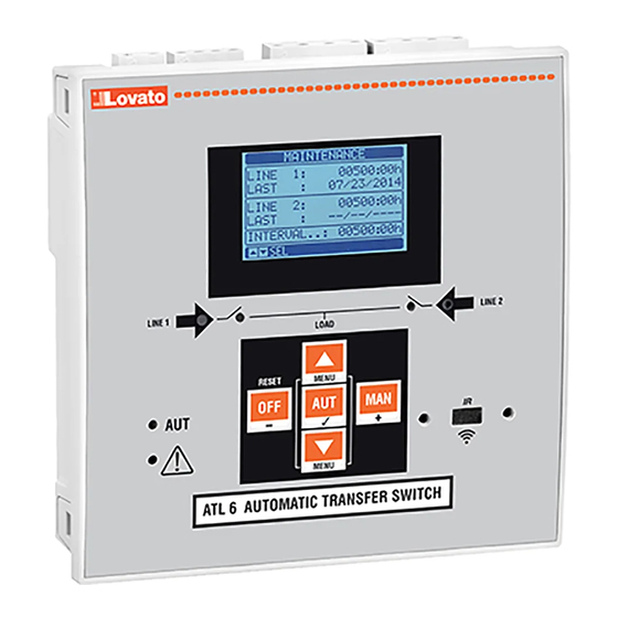
Page 3: Funzione Dei Tasti Frontali
1 breaker. If flashing, indicates a mismatch tra lo stato desiderato dell’ATL600 e lo stato vero rilevato dal segnale di between the desired state of the breaker and its true state detected by the feedback. -
Page 4: Messa In Tensione
(interruttori motorizzati, commutatori motorizzati o contattori). Messa in tensione Power-up ATL600 ha alimentazione 100-240VAC. ATL600 has 100-240VAC supply. ATL610 ha alimentazione 100-240VAC o 12-24VDC. In caso di ATL610 has 100-240VAC or 12-24VDC supply. In the case of the... -
Page 5: Accesso Tramite Password
Accesso tramite password Password access La password serve per abilitare o bloccare l’accesso al menu di The password is used to enable or lock the access to setting menu impostazione ed al menu comandi. (setup) and to commands menu. Per gli apparecchi nuovi di fabbrica (default), la password è disabilitata e For brand-new devices (factory default), the password management is l’accesso è... - Page 6 Statistiche Statistics Line 2 AUT mode MAN mode Line1 Contatore Linea 1 Linea 2 Contatore commutation commutazioni commutation commutazioni counter in modalità counter in modalità Contatore Time lapse Contatore Tempo allarmi A03 with load trascorso con allarmi A03 supplied carico alimentato Tempo Time lapse...
-
Page 7: Espandibilità
Lista Eventi Event List Event code Codice evento Data e ora evento Descrizione Description evento of event Synoptic Sinottico Note: Some of the pages listed above may not be displayed if the Nota: Alcune delle pagine elencate sopra potrebbero non essere relevant function is disabled. -
Page 8: Risorse Aggiuntive
pagina del display (moduli espansione), dove si vedono il numero, il tipo display (expansion modules), where it is possible to see the number, the e lo stato dei moduli collegati. type and the status of the modules. La numerazione degli I/O viene elencata sotto ogni modulo. The I/O numbering is shown under each module. -
Page 9: Soglie Limite (Limx)
Soglia inferiore Stato variabile limite Variabili da remoto (REMx) Remote-controlled variables (REMx) ATL600 e ATL610 hanno la possibilità di gestire un massimo di 16 ATL600 and ATL610 can manage up to 16 remote-controlled variables variabili comandate da remoto (REM1…REM16). (REM1…REM16). -
Page 10: Allarmi Utente (Uax)
Allarmi utente (UAx) User Alarms (UAx) L’utente ha la possibilità di definire un massimo di 4 allarmi The user has the possibility to define a maximum of 4 programmable programmabili (UA1…UA4). alarms (UA1…UA4). Per ciascun allarme è possibile stabilire: For each alarm, it is possible to define: la sorgente, cioè... -
Page 11: Blocco Tastiera
un trasferimento del carico esattamente come nel ciclo automatico. You can stop the simulation at any time by passing in OFF mode. E’ possibile arrestare la simulazione in qualsiasi momento passando in If you make the simulation through commands menu, you must start modalità... -
Page 12: Impostazione Parametri Da Pc
Impostazione parametri da PC Parameter setting (setup) with PC Mediante il software di set-up ATL Remote Control è possibile You can use the ATL Remote control set-up software to transfer effettuare il trasferimento dei parametri di set-up (precedentemente (previously programmed) set-up parameters from the ATL6.. to the hard impostati) da ATL6.. - Page 13 Nella seguente tabella sono elencati i sottomenu disponibili: The following table lists the available submenus: Cod. MENU DESCRIZIONE Cod. MENU DESCRIPTION UTILITA’ Lingua, luminosità, pagine display ecc. UTILITY Language, brightness, display pages, etc. GENERALE Dati caratteristici dell’impianto GENERAL System specifications PASSWORD Impostazione codici di accesso PASSWORD...
-
Page 14: Tabella Dei Parametri
Quando si è in modalità modifica, il valore può essere modificato con i When the editing screen is displayed, the parameter setting can be tasti + e -. Vengono visualizzati anche una barra grafica che indica il modified with + and -keys. The screen shows the new setting, a graphic range di impostazione, i valori minimi e massimi possibili, il valore bar that shows the setting range, the maximum and minimum values, the precedente e quello di default. - Page 15 Inversa = L3-L2-L1. Nota: Abilitare anche i corrispondenti allarmi. P02.06 – Choosing the type of connection, three-phase with / without neutral, two-phase or P02.06 – Scelta del tipo di connessione, trifase con/senza neutro, bifase o monofase. single phase. P02.07 – Controlli di tensione effettuati su concatenate, tensioni di fase o entrambe. P02.07 –...
- Page 16 P05.03 – Tempo che intercorre tra la avvenuta apertura del dispositivo di commutazione P05.03 – Time from the opening of the LINE 1 switchgear, after which the LINE 2 switchgear LINEA 1 e il comando di chiusura del dispositivo di commutazione LINEA 2. closing command is given.
- Page 17 P06.04 Limite tensione MAX sgancio 100-130 / OFF P06.04 MAX voltage limit for trip 100-130 / OFF P06.05 Soglia MAX ripristino 100-130 / OFF P06.05 MAX voltage pick-up 100-130 / OFF P06.06 Ritardo tensione MAX 0-600 P06.06 MAX voltage delay 0-600 P06.07 Ritardo rientro rete nei limiti...
- Page 18 OFF+GLOB OFF+GLOB ON+GLOB ON+GLOB P07.18 Controllo LINEA 2 in modo MAN P07.18 LINE 1 control MAN mode OFF+GLOB OFF+GLOB ON+GLOB ON+GLOB P07.19 Tempo ritardo avviamento generatore OFF / 1-6000 P07.19 Time delay generator starter due to a lack OFF / 1-6000 in seguito a mancanza LINEA 2 of LINE 2 P07.20...
- Page 19 P09.10 – P09.11 Stabilisce l’ora e i minuti di inizio del test periodico. Attenzione!! L’orologio P09.10 – P09.11 Sets the time (hour and minutes) when the periodic test starts. Warning!! The calendar clock must be set to the right date and time. datario deve essere impostato correttamente.
- Page 20 P13.n.11 Stato a riposo OFF-ON P13.11 Idle state OFF-ON P13.n.12 Memoria OFF-ON P13.12 Memory OFF-ON Nota: questo menu è diviso in 4 sezioni, per le soglie limite LIM1…4 Note: this menu is divided into 4 sections for the limit thresholds LIM1…4 P13.01 –...
-
Page 21: Allarmi
Allarmi Alarms Al sorgere di un allarme, il display mostra una icona di allarme, un When an alarm is generated , the display will show an alarm icon, the codice identificativo e la descrizione dell’allarme nella lingua code and the description of the alarm in the language selected. selezionata. -
Page 22: Descrizione Degli Allarmi
Descrizione degli allarmi Alarm description DESCRIPTION ALARM EXPLANATION DESCRIZIONE MOTIVAZIONE ALLARME Tensione batteria Tensione di batteria al di fuori della soglia minima per un Battery voltage too Battery voltage beyond the lowest threshold for a time troppo bassa tempo superiore a quello impostato. exceeding the time set. - Page 23 Funzione Descrizione Function Description Disabilitato Ingresso disabilitato Disabled Input disabled Configurabile Libera configurazione utente Configurable Free user configuration Interruttore linea 1 chiuso Contatto ausiliario che informa l’ATL dello stato di Line 1 breaker closed Auxiliary contact informing the ATL of the open/closed (Feedback 1) aperto/chiuso dell’interruttore linea 1.
-
Page 24: Tabella Funzioni Uscite
Tabella funzioni uscite Output function table La tabella seguente riporta tutte le funzioni che possono essere The following table shows all the functions that can be attributed to the associate alle uscite digitali programmabili OUTn. OUTn programmable digital inputs. Ciascuna uscita può essere poi impostato in modo da avere funzione Each output can be configured so it has a normal or reverse (NOR or normale o invertita (NOR o REV). -
Page 25: Installazione
To quit command menu press RESET. Installazione Installation ATL600 è destinato al montaggio da incasso. Con il corretto montaggio ATL600 is designed for flush-mount installation. With proper mounting, it e la guarnizione opzionale garantisce una protezione frontale IP65. guarantees with the optional gasket IP65 front protection. -
Page 26: Schemi Di Connessione
Schemi di connessione Wiring diagrams Comando interruttori motorizzati Control of motorised circuit breakers Programmazione parametri per lo schema in figura Parameter setting for the wiring diagram in picture Morsetto Codice parametro Impostazione Terminal Parameter code Setting P05.07 Interruttori Impulso o Interruttori continuo Breaker pulse or breaker continuous 15(INP1) P10.01.01... - Page 27 Comando Commutatore motorizzato Control of motorized changeover switch Programmazione parametri per lo schema in figura Parameter setting for the wiring diagram in picture Morsetto Codice parametro Impostazione Terminal Parameter code Setting P05.07 Commutatore impulso o Commutatore continuo Changeover pulse or Changeover continuous 15(INP1) P10.01.01 Interruttore linea 1 chiuso (Feedback 1)
- Page 28 Comando contattori Control of contactors Programmazione parametri per lo schema in figura Parameter setting for the wiring diagram in picture Morsetto Codice parametro Impostazione Terminal Parameter code Setting P05.07 Contattori Contactors 15(INP1) P10.01.01 Interruttore linea 1 chiuso (Feedback 1) Line 1 breaker closed (Feedback 1) 16(INP2) P10.02.01 Interruttore linea 2 chiuso (Feedback 2)
- Page 29 Dual power supply implementation with auxiliary voltage control by mediante dispositivo Lovato electric codice ATLDPS1 Lovato Electric dual power supply relay code ATLDPS1 Esecuzione Dual Power Supply con controllo tensione ausiliaria Dual Power Supply implementation with auxiliary voltage control by mediante relè...
- Page 30 Linea 2 proveniente da generatore Line 2 coming from generator Controllo tensione ausiliaria mediante ATL600 + AC Dual Power Supply opzionale (impianto Auxiliary voltage control by ATL600 + optional AC Dual Power Supply (battery supply not sprovvisto di alimentazione da batteria) available)
-
Page 31: Disposizione Morsetti
Disposizione morsetti Terminals position Dimensioni meccaniche e foratura pannello (mm) Mechanical dimensions and front panel cut-out (mm) - Page 32 Caratteristiche tecniche Technical characteristics Alimentazione AC: morsetti 13, 14 AC Supply : terminals 13, 14 100 - 240V~ 100 - 240V~ Tensione nominale Us Rated voltage Us 110 - 250V= 110 - 250V= 90 - 264V~ 90 - 264V~ Limiti di funzionamento Operating voltage range 93,5 - 300V= 93.5 - 300V=...
- Page 33 Tensione di isolamento Insulation voltage Alimentazione AC AC Supply Ui 250V~ Tensione nominale d’isolamento Rated insulation voltage Ui 250V~ Uimp 6kV Tensione nomi. di tenuta a impulso Rated impulse withstand voltage Uimp 6kV Tensione di tenuta a frequenza d’esercizio Power frequency withstand voltage Ingressi voltmetrici Linea1 e Linea 2 Line 1 and Line 2 voltage inputs Ui 480V~...
-
Page 34: Cronologia Revisioni Manuale
Cronologia revisioni manuale Manual revision history Data Note Date Notes 30/07/2014 30/07/2014 Prima revisione First release 26/09/2014 Aggiornamento schemi 26/09/2014 Schemas updating 02/12/2014 02/12/2014 Inserita espansione EXP1014. Added expansion EXP1014. Modificato parametro P05.03, P05.04. Changed parameters P05.03, P05.04. Inserito blocco tastiera. Added keypad lock.
Need help?
Do you have a question about the ATL600 and is the answer not in the manual?
Questions and answers