LOVATO ELECTRIC ATL 500 Instruction Manual
Automatic transfer switch controller
Hide thumbs
Also See for ATL 500:
- Instruction manual (14 pages) ,
- Instruction manual (14 pages) ,
- Instruction manual (14 pages)
Table of Contents
Advertisement
Quick Links
LOV TO ELECTRIC S.P. .
24020 GORLE (BERGAMO) ITALIA
VIA DON E. MAZZA, 12
TEL. 035 4282111
L
E
E-mail info@
ovato
lectric.com
L
E
Web
www.
ovato
lectric.com
W RNING!
– Carefully read the manual before the installation or use.
– This equipment is to be installed by qualified personnel, complying to current standards, to avoid
damages or safety hazards.
– Before any maintenance operation on the device, remove all the voltages from measuring and supply inputs and short-
circuit the CT input terminals.
– The manufacturer cannot be held responsible for electrical safety in case of improper use of the equipment.
– Products illustrated herein are subject to alteration and changes without prior notice. Technical data and descriptions
in the documentation are accurate, to the best of our knowledge, but no liabilities for errors, omissions or
contingencies arising there from are accepted.
– A circuit breaker must be included in the electrical installation of the building. It must be installed close by the
equipment and within easy reach of the operator. It must be marked as the disconnecting device of the equipment:
IEC /EN 61010-1 § 6.11.3.1.
– Clean the device with a soft dry cloth; do not use abrasives, liquid detergents or solvents.
TTENTION !
– Lire attentivement le manuel avant toute utilisation et installation.
– Ces appareils doivent être installés par un personnel qualifié, conformément aux normes en vigueur en
matière d'installations, afin d'éviter de causer des dommages à des personnes ou choses.
– Avant toute intervention sur l'instrument, mettre les entrées de mesure et d'alimentation hors tension et court-circuiter
les transformateurs de courant.
– Le constructeur n'assume aucune responsabilité quant à la sécurité électrique en cas d'utilisation impropre du
dispositif.
– Les produits décrits dans ce document sont susceptibles d'évoluer ou de subir des modifications à n'importe quel
moment. Les descriptions et caractéristiques techniques du catalogue ne peuvent donc avoir aucune valeur
contractuelle.
– Un interrupteur ou disjoncteur doit être inclus dans l'installation électrique du bâtiment. Celui-ci doit se trouver tout
près de l'appareil et l'opérateur doit pouvoir y accéder facilement. Il doit être marqué comme le dispositif
d'interruption de l'appareil : IEC/ EN 61010-1 § 6.11.3.1.
– Nettoyer l'appareil avec un chiffon doux, ne pas utiliser de produits abrasifs, détergents liquides ou solvants.
CHTUNG!
– Dieses Handbuch vor Gebrauch und Installation aufmerksam lesen.
– Zur Vermeidung von Personen- und Sachschäden dürfen diese Geräte nur von qualifiziertem
Fachpersonal und unter Befolgung der einschlägigen Vorschriften installiert werden.
– Vor jedem Eingriff am Instrument die Spannungszufuhr zu den Messeingängen trennen und die Stromwandler
kurzschlie en.
– Bei zweckwidrigem Gebrauch der Vorrichtung übernimmt der Hersteller keine Haftung für die elektrische Sicherheit.
– Die in dieser Broschüre beschriebenen Produkte können jederzeit weiterentwickelt und geändert werden. Die im
Katalog enthaltenen Beschreibungen und Daten sind daher unverbindlich und ohne Gewähr.
– In die elektrische Anlage des Gebäudes ist ein Ausschalter oder Trennschalter einzubauen. Dieser muss sich in
unmittelbarer Nähe des Geräts befinden und vom Bediener leicht zugänglich sein. Er muss als Trennvorrichtung für das
Gerät gekennzeichnet sein: IEC/ EN 61010-1 § 6.11.3.1.
– Das Gerät mit einem weichen Tuch reinigen, keine Scheuermittel, Flüssigreiniger oder Lösungsmittel verwenden.
DVERTENCI
– Leer atentamente el manual antes de instalar y utilizar el conmutador.
– Este dispositivo debe ser instalado por personal cualificado conforme a la normativa de instalación
vigente a fin de evitar daños personales o materiales.
– Antes de realizar cualquier operación en el dispositivo, desconectar la corriente de las entradas de alimentación y
medida, y cortocircuitar los transformadores de corriente.
– El fabricante no se responsabilizará de la seguridad eléctrica en caso de que el dispositivo no se utilice de forma
adecuada.
– Los productos descritos en este documento se pueden actualizar o modificar en cualquier momento. Por consiguiente,
las descripciones y los datos técnicos aquí contenidos no tienen valor contractual.
– La instalación eléctrica del edificio debe disponer de un interruptor o disyuntor. Éste debe encontrarse cerca del
dispositivo, en un lugar al que el usuario pueda acceder con facilidad. Además, debe llevar el mismo marcado que el
interruptor del dispositivo (IEC/ EN 61010-1 § 6.11.3.1).
– Limpiar el dispositivo con un trapo suave; no utilizar productos abrasivos, detergentes líquidos ni disolventes.
UPOZORNĚNÍ
AVERTIZARE!
GB
UTOM TIC TR NSFER SWITCH CONTROLLER
Instructions manual
ES
CONMUT DOR UTOMÁTICO DE RED
Manual de instrucciones
TL 500
TTENZIONE!
– Leggere attentamente il manuale prima dell'utilizzo e l'installazione.
– Questi apparecchi devono essere installati da personale qualificato, nel rispetto delle vigenti normative
impiantistiche, allo scopo di evitare danni a persone o cose.
– Prima di qualsiasi intervento sullo strumento, togliere tensione dagli ingressi di misura e di alimentazione e
cortocircuitare i trasformatori di corrente.
– Il costruttore non si assume responsabilità in merito alla sicurezza elettrica in caso di utilizzo improprio del dispositivo.
– I prodotti descritti in questo documento sono suscettibili in qualsiasi momento di evoluzioni o di modifiche. Le
descrizioni ed i dati a catalogo non possono pertanto avere alcun valore contrattuale.
– Un interruttore o disgiuntore va compreso nell'impianto elettrico dell'edificio. Esso deve trovarsi in stretta vicinanza
dell'apparecchio ed essere facilmente raggiungibile da parte dell'operatore. Deve essere marchiato come il dispositivo
di interruzione dell'apparecchio: IEC/ EN 61010-1 § 6.11.3.1.
– Pulire l'apparecchio con panno morbido, non usare prodotti abrasivi, detergenti liquidi o solventi.
UW G !
ПРЕДУПРЕЖДЕНИЕ!
DİKKAT!
1
Advertisement
Table of Contents

Related Manuals for LOVATO ELECTRIC ATL 500


Summary of Contents for LOVATO ELECTRIC ATL 500
- Page 1 UTOM TIC TR NSFER SWITCH CONTROLLER Instructions manual LOV TO ELECTRIC S.P. . CONMUT DOR UTOMÁTICO DE RED 24020 GORLE (BERGAMO) ITALIA VIA DON E. MAZZA, 12 Manual de instrucciones TEL. 035 4282111 E-mail info@ ovato lectric.com www. ovato lectric.com TL 500 W RNING! TTENZIONE!
-
Page 2: Table Of Contents
ATL 500 es un conmutador automático de redes que permite conmutar de manera automática o manual ATL 500 is an automatic transfer switch controller for the automatic or manual switching of the load from la carga de una línea principal (“MAIN LINE”) a una línea de seguridad o reserva (“SECONDARY LINE”) y the MAIN LINE to a stand-by or emergency SECONDARY LINE and vice versa. -
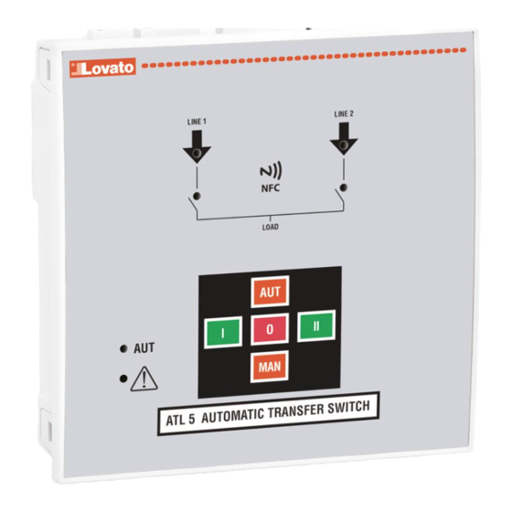
Page 3: Front Leds
POWER-UP PUESTA EN MARCHA – ATL 500 has self-seeking power supply from the two measurement inputs 110...240VAC. It means – El conmutador ATL 500 incorpora autoalimentación doble (autobúsqueda) de 110 a 240VAC. that it is self-powered by automatically selecting the best line available between LINE 1 and LINE 2, Esto significa que selecciona automáticamente la línea de alimentación más adecuada de las dos,... -
Page 4: Programmable Inputs And Outputs
(activo). – If a password is set in the ATL 500 (see menu M02 - Password), this must be known, otherwise the – cuando se configura una contraseña en el conmutador ATL 500 (véase el menú M02 - Contraseña), access to parameters will not be possible (the App requires to entry the password). - Page 5 LOVATO NFC App: QR code for the download of the LOVATO NFC App: – In the following table there is the lists of available submenus: – En la tabla siguiente se muestran los menús disponibles: Code MENU DESCRIPTION Cód. MENÚ DESCRIPCIÓN GENERAL System specifications...
-
Page 6: Parameters Table
P04.07 – If this parameter is enabled, after a transfer to the secondary line, restore to main line does not suministro de carga. Nota: cuando faltan completamente las dos líneas, el conmutador ATL 500 deja de occur automatically when the latter becomes available again, but it must be commanded in manual recibir alimentación y no se genera ninguna alarma. - Page 7 M05 - LINE 1 CONTROL / CONTROL DE LÍNEA 1 Default/por defecto Range/Rango P05.01 MIN voltage limit / Límite de tensión MÍN. 70-100 P05.02 MIN voltage pick-up / Umbral MÍN. restablecimiento 70-100 P05.03 MIN voltage delay / Retardo de tensión MÍN. POT/0-600 P05.04 MAX voltage limit / Límite de tensión MÁX.
-
Page 8: Alarms
= alarma A01, 2 parpadeos = alarma A02, 3 parpadeos = alarma A03 y así sucesivamente). – Alarms can be reset by pressing the MAN key. Note. After pressing MAN key the ATL 500 goes in El significado de la alarma se describe en la tabla de alarmas. -
Page 9: Alarms Description
Auxiliary contact informing the ATL 500 of the open/closed status of LINE 1 Realimentación de LÍNEA 1 Contacto auxiliar que indica a la unidad ATL 500 si el dispositivo de changeover device. If this signal is not connected, ATL 500 considers the conmutación de la LÍNEA 1 está... -
Page 10: Programmable Outputs Function Table
Control del generador INSTALLATION INSTALACIÓN – ATL 500 is designed for flush-mount installation. With proper mounting, it guarantees with the – El conmutador ATL 500 está diseñado para montarse empotrado. Cuando está correctamente montado, la EXP80 01 optional gasket IP65 front protection. -
Page 11: Wiring Diagrams
WIRING DIAGRAMS ESQUEMAS DE CONEXIÓN Control of contactors – three-phase connection Control de contactores – conexión trifásica Note: for two-phase connection, connect the terminals L1-L2-N. Nota: utilice los terminales L1-L2-N en la conexión bifásica. Parameter setting for the wiring diagram in picture Programación de parámetros correspondiente al esquema de la figura Terminal Parameter code... - Page 12 Dual power supply implementation with auxiliary voltage control for motorized changeover by Alimentación dual con control de tensión auxiliar de conmutador motorizado mediante dispositivo LOVATO Electric dual power supply relay code AT LDPS1 LOVATO Electric con código ATL DPS1 ATL DPS1...
-
Page 13: Terminals Position
TERMINALS POSITION DISPOSICIÓN DE LOS TERMINALES L1 L2 L3 N L1 L2 L3 N LINE 1 LINE 2 110-240V~ LN 110-240V~ LN 190-415V~ 3N 190-415V~ 3N 50/60Hz 50/60Hz OUT1 - OUT3 B300 / 250V~ 8A AC1 / 1A 30V= PILOT DUTY MECHANICAL DIMENSIONS AND FRONT PANEL CUT-OUT [mm] DIMENSIONES MECÁNICAS Y ESCOTADURA DEL PANEL [mm] 43.3... -
Page 14: Technical Characteristics
TECHNICAL CHARACTERISTICS CARACTERÍSTICAS TÉCNICAS LINE 1 and LINE 2 voltage inputs: terminals 1-4 and 5-8 Entradas de monitorización de tensión de LÍNE 1 y LÍNE 2, terminales 1-4 y 5-8 Rated voltage 110...240V~ LN / 190...415V~ 3N Tensión nominal 110 a 240V~ LN / 190 a 415V~ 3N Operating voltage range 90...300V~ LN / 155...519V~ 3N Límites de funcionamiento con tensión...
Need help?
Do you have a question about the ATL 500 and is the answer not in the manual?
Questions and answers