
Related Manuals for Spirit CG800


Summary of Contents for Spirit CG800
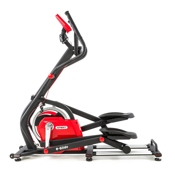
- Page 1 Group Exercise Elliptical OWNER’S MANUAL Please carefully read this entire manual before operating your group exercise elliptical!
-
Page 2: Table Of Contents
TABLE OF CONTENTS Important Safety Instructions…………………………………………………………….…. Features………………………………………………………………………………….…..Assembly Instructions…………………………………………………………………….…. Console Operation……………..………………………….……………………….………… Maintenance………………………………………………………………………………….. Exploded view and parts list………………………………………………………………… SE880-YE04_1807B(SP) -
Page 3: Important Safety Instructions
IMPORTANT SAFETY INSTRUCTIONS WARNING - Read all instructions before using this appliance. elliptical ■ Do not operate on deeply padded, plush or shag carpet. Damage to both carpet elliptical may result. elliptical ■ Keep children away from the . There are obvious pinch points and other caution areas that can cause harm. -
Page 4: Features
Features This all new product from the company is a next generation elliptical machine specially designed for use with group exercise workouts or for serious training at home. Here are the top reasons why we believe the group exercise elliptical is among the best elliptical machines available, for everyone: •... -
Page 5: Assembly Instructions
ASSEMBLY INSTRUCTIONS Step1 #58. M10 x 20mm #65. Split washer M10 Stainless steel bolt #129. M10 x 25mm Stainless steel bolt Step2 #58. M10 x 20mm #32. Cup washer Stainless steel bolt #59. M5 x 10mm #145. 25mm Phillips head screw Wave Washer... - Page 6 Step3 #45. 5/16” Nut #44. 5/16” x 1-3/4” Bolt #59. M5 x 10mm head Phillips screw Step4 #110. M10 Nut #74. M10 x 38mm Shoulder Bolt...
- Page 7 Tools #117- 17mm Wrench #115- Phillips Head #116- 8mm Allen Wrench Screw Driver #118. 12mm Allen Wrench #120. 13 &14 m/m Wrench #119. 5mm Allen Wrench...
- Page 8 STEP 1: CONSOLE MAST The tension adjustment cable and speed sensor wire are pre-installed to the console mast and main frame so be careful not to pull too hard on the console mast during assembly to avoid damaging them. Connect the two speed sensor wires together. ...
- Page 9 STEP 2: SWING ARMS & PEDALS Put one wave washer (145) at each side of the mast axle prior to sliding the two swing arms ( 9 Right & 10 Left ) onto the console mast axle. There is a left and right swing arm ( marked with an “R”...
- Page 10 STEP 3: CONSOLE Assemble the transport wheels (79) with the two 5/16” x 1-3/4” bolts (44) and 5/16” nuts (45). Unpack the console and install the 3 AA batteries. Connect the speed sensor wire into the white two pin connector accessed through the opening in the back of the console. Mount the console onto the console mast plate and secure with four M5 x 10mm screws (59).
- Page 11 STEP 4: SWING ARMS Assemble the bracket at the bottom of the swing arms to the rod ends on the pedal arms using the M10 x 38mm shoulder bolts (74) and the M10 nuts (110). Tighten securely.
- Page 12 STEP 5: LEVELERS & END CAPS Tilt the elliptical to one side and put something under the unit for support and install the three levelers (40) for that side. Tilt the unit to the other side and install those three levelers (40). Level the elliptical once it is positioned where it will be used.
-
Page 13: Console Operation
CONSOLE OPERATION Power The power for the console is provided by 3 AA alkaline batteries (provided) and will operate on rechargeable NiCd AA batteries. Once the batteries are installed the console will power on, the Time window will display an hour meter reading, the Distance window will display an odometer reading and the RPM/Cadence window will display the software version. - Page 14 Displays Time: Displays workout time two ways; either count up (accumulated time) or count down (remaining time), depending on your preference selected before starting the timer. Speed/Cadence/ RPM: Displays the current pedaling speed as revolutions per minute. Displays Speed in mph or kph, depending on setting, when the Display key is pressed. Distance/Calories: Displays virtual distance traveled in miles or kilometers (units selected through management mode, see page 13 for details).
-
Page 15: Maintenance
MAINTENANCE The elliptical is practically maintenance free. Just keep it clean by wiping down the unit with a damp cloth after each use. Do not use harsh detergents. Every month check that all the hardware is securely tightened. Do not use the elliptical if any parts are loose or broken. No Lubrication should be applied on the wheels and aluminum tracks, only need to be kept clean to prevent noise and maintain smoothness. -
Page 16: Exploded View And Parts List
EXPLODED VIEW DIAGRAM... - Page 17 PARTS LIST Dwg # Part description Q’ty Main Frame Console Mast Handlebar Assembly Sliding Pedal Arm (R) Sliding Pedal Arm (L) Connecting Pedal Arm (R) Connecting Pedal Arm (L) Main Crank Axle Swing Arm (R) Swing Arm (L) Crank Arm Console Mounting Plate 15-1 Flywheel covers Bearing Housing, Crank Axle...
- Page 18 Dwg # Part description Q’ty Split Washer M5 Split Washer M6 Split Washer M8 Split Washer M10 (Stainless steel) Nut M5 - 4t Flat Head Socket Screw M4 × 10mm (Stainless steel) Idler Adj. Bolt M10 × 1.5 × 220L Shoulder Bolt 14mm dia x M10 x 38mm Riv-Nut 13mm dia ×- M10 ×...
- Page 19 Dwg # Part description Q’ty Phillips HeadScrew Driver 8th L Allen Wrench 17m/m_Combination Wrench 12th L Allen Wrench 5th L Allen Wrench 13.14m/m_Wrench Idler Wheel 35 Retaining Ring for Bore Socket Head Cap Bolt M10 × 1.5 - 80mm Socket Head Cap Bolt M10 × 1.5 - 25mm (Stainless steel) Flywheel Pulley Ø174 Drive Axle...
Need help?
Do you have a question about the CG800 and is the answer not in the manual?
Questions and answers