Sign In
Upload
Manuals
Brands
Flowserve Manuals
Controller
Limitorque QX
Flowserve Limitorque QX Manuals
Manuals and User Guides for Flowserve Limitorque QX. We have
2
Flowserve Limitorque QX manuals available for free PDF download: User Instructions, Maintenance And Spare Parts
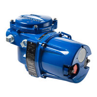
Flowserve Limitorque QX User Instructions (96 pages)
Electronic
Brand:
Flowserve
| Category:
Controller
| Size: 6 MB
Table of Contents
Table of Contents
2
1 Important Notes
7
Figure 1.1 - QX-05 Actuator
7
Limitorque QX Electronic Actuator FCD LMENIM3306-06
7
2 Quick Start
9
Calibrate Position Limits
10
Electrical Operation Feature
10
Handwheel Operation Feature
12
Figure 2.1 - Electrical Operation
12
Figure 2.2 - Handwheel Operation
14
Figure 2.3 - QX Travel Stops
14
Limitorque QX Electronic Actuator FCD LMENIM3306-06
14
Entering the Setup Mode
15
DDC Option
15
Check the Settings
15
3 Installation and Operation
16
Preparing the Stem Nut
16
Torque Applications
16
Table 3.1 - Available QX Flanges
16
Figure 3.1 - Top View - Stem Nut with Standard Keyway Position
17
Figure 3.2 - Exploded View of QX Bases
17
Mechanical Installation Onto Valve or Gearbox
18
Electrical Connections
18
Removing Terminal Cover
18
Terminal Compartment Documents
18
Sealing Cable/Conduit Entries
19
Recommended Terminal Connections
19
Figure 3.3 - Power Terminal Connector Size Limitations
19
Figure 3.4 - Terminal Block
20
Figure 3.5 - Control Terminal Connector Size Limitations
20
Table 3.2 - Terminal Block Rating; Power Terminals
20
Termination of Cables
21
Cable Connections
21
Table 3.3 - Terminal Block Rating; Control Terminals
21
Network Installations
22
Figure 3.6 - View of Terminal Block
22
Table 3.4 - Required Ratings for External Wires
22
Figure 3.7 - Standard Wiring Diagram - Three Phase Shown
23
Figure 3.8 - Removing Outer Plastic Jacket
23
Figure 3.9 - Separating Cable Parts
24
Figure 3.10 - Stripping Conductors and Applying Heat Shrink Tubing
24
Figure 3.11 - Ring Tongue Connectors
24
Foundation Fieldbus Installation
25
Table 3.5- Loop Topology Connections
25
Network Wiring - Profibus DP/PA Installation
26
Table 3.6 - Foundation Fieldbus Connections
26
Table 3.7 - Profibus Cable Specifications
26
Network Wiring - Devicenet
27
Replacing Terminal Cover
27
External Earth/Ground Connections
27
Terminal Block Shield Installation
27
Table 3.8 - Devicenet Cable Specifications
27
Commissioning the Actuator
28
Default Configuration Set
28
Figure 3.12 - Terminal Block Shield
28
Figure 3.13 - User Network Connection for Loop Topology
29
Figure 3.14 - External Earth/Ground Connection - Housing
29
Table 3.9 - Default Configurations
29
View the Existing Settings
30
Entering the Setup Mode
30
Setting Position Limits
31
Figure 3.15 - View Settings
31
Figure 3.16 - Position Setup - Electrical Operation
33
Operating the QX Actuator
34
Manual Operation
34
Electrical Operation
34
Local Control
34
Figure 3.17 - Declutch Lever Shows Direction of Engagement (QX-05 Shown)
34
Remote Control
35
Local Indication
35
Figure 3.18 - Control Panel
35
Table 3.10 - LED Indicators - Default Settings
36
4 Customizing the Actuator
37
Changing the Existing Settings
37
Figure 4.1 - Entering the Setup Mode
38
Figure 4.2 - Main Menu Selections
38
Password Entry
39
Figure 4.3 - Changing Settings
39
New Password
40
Figure 4.4 - Password Entry
40
Figure 4.5 - New Password
40
Valve Setup
41
Close Direction
41
Close Seating
41
Open Seating
41
Figure 4.6 - Valve Setup
41
Torque Switch Timer
42
Status
42
Torque Timer
42
Figure 4.7 - Torque Switch Timer
42
Operating Time
43
Torque Setup
43
Figure 4.8 - Operating Time Setup
43
Figure 4.9 - Torque Setup
43
Close Torque Valve or Open Torque Valve
44
Position Setup
44
Set Position Limits for Electrical Operation
44
Figure 4.10 - Typical XP Nameplate
44
Set Position Limits for Manual Operation
45
Figure 4.11 - Electrical Operation
46
Figure 4.12 - Handwheel Operation
46
Modutronic Option
47
Status
47
Proportional Band
47
Fail Position
47
Deadband
47
Polarity (20 Ma)
47
Delay after Stop
48
Ma Signal Range
48
Set High Reference
48
Set Low Reference
48
Figure 4.13 - Modutronic Option
48
Modutronic LCD Display
49
DDC Option
49
Status
49
Figure 4.14 - Modutronic Signals
49
Network Address
50
Protocol
50
Analog Scale
50
ESD Action
50
Figure 4.15 - DDC
50
Proportional Band
51
Deadband
51
Offset
51
Move to
51
Comm Loss Delay
51
Comm Loss Action
51
FF Option
51
Status
52
Terminate Bus
52
Analog Scale
52
ESD Action
52
OPEN/CLOSE Mode
52
Proportional Band
52
Deadband
52
Comm Loss Delay
53
Comm Loss Action
53
PB Option
53
Figure 4.16 - Foundation Fieldbus
53
Figure 4.17 - Profibus DP
54
PB DP Operation
54
Status
54
Comm Loss Action
55
Comm Loss Delay
55
DN Option
55
Figure 4.18 - Profibus PA
55
Baud Rate
56
Deadband
56
ESD Action
56
Network Address
56
Proportional Band
56
Status
56
Comm Loss Action
57
Comm Loss Delay
57
Status and Alarm Contacts
57
Figure 4.19 - DN Option
57
Status and Alarm Contact Default Settings
58
Status Function
58
Contact
59
Valve Position
59
Two-Speed Timer (Optional)
59
Status 59
59
Start Position
59
Figure 4.20 - Status and Alarm Contacts (Shown with Optional Boards Added)
59
Stop Position
60
Pulse Time - on
60
Pulse Time - off
60
Change Analog out
60
Figure 4.21 - Two-Speed Timers
60
Figure 4.22 - Change Analog out
61
Figure 4.23 - Change Analog out Voltage - APT
61
Figure 4.24 - Change Analog out Current - APT
61
APT Polarity Option
62
Figure 4.25 - Change Analog out Voltage - ATT
62
Figure 4.26 - Change Analog out Current - ATT
62
ATT Polarity Option
63
Remote Mode
63
Figure 4.27 - Remote Mode
63
Local Control
64
LED Customization
64
ESD (Emergency Shutdown) Overrides
64
Figure 4.28 - Local Control
64
ESD Override
65
Figure 4.29 - ESD Overrides
65
Inhibit
65
Jammed Valve
65
Local Command
65
Stop
65
Lost Phase
66
Motor Thermostat
66
Oil over Temperature
66
Overtorque
66
Two-Speed Timer
66
Network ESD
67
Torque Switch Timer
67
Inputs
67
Input Standard Remote Control
67
Status
68
Custom Input Mode #1 - Momentary ESD/PSESD (Optional)
68
Figure 4.30 - Inputs
68
Figure 4.31 - Custom Input Mode
70
Custom Input Mode #2 - Momentary ESD/CSE (Optional)
71
Custom Input Mode #3 - ESD Time Delay Relay
71
Custom Input Mode #4 - Multi-Position Mode (Optional)
72
Table 4.1 - Digital Input Terminals
72
Monitor Relay
73
Diagnostic Reset
74
Figure 4.32 - Monitor Relay
74
TAG Number
75
Figure 4.33 - Diagnostic Reset
75
Figure 4.34 - TAG Number
75
LCD Contrast
76
Motor Thermostat
76
Change Valve Data
76
Figure 4.35 - LCD Contrast
76
Figure 4.36 - Motor Thermostat
76
Change Port
77
Figure 4.37 - Change Valve Data
77
Figure 4.38 - Change Port and Bluetooth Settings
77
5 Troubleshooting
78
View Diagnostics Routine
79
Troubleshooting Problems/Corrective Action
79
Actuator Fails to Operate
79
Jammed Valve Detected
80
Actuator Operates but Does Not Drive Valve
80
Valve Does Not Seat Correctly
80
Status Messages
81
View Diagnostics
83
Figure 5.1 - Initialize Routine
83
View Hardware Status
84
Figure 5.2 - Diagnostic Overview
84
Figure 5.3 - View Hardware Status
84
View Motor Status
85
View Power Supply
85
View Identification
85
Figure 5.4 - View Motor Status
85
Figure 5.5 - View Power Supply
85
View Torque Profile
86
View Operation Log
86
Figure 5.6 - View Identification
86
Figure 5.7 - View Torque Profile
86
Figure 5.8 - View Operation Log
87
View DNET Status
88
Figure 5.9 - View DNET Status
88
6 Maintenance
90
Lubrication
90
Oil Capacities
90
Checking Oil Level
90
Table 6.1 - Oil Capacities
90
7 Regulatory Information
91
Specific Conditions for Safe Use - Atex/Cenelec/Iecex Applications
94
Statement of Compliance with Applicable European Directives
94
Figure 7.1 - Typical ATEX Nameplate
95
Advertisement
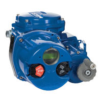
Flowserve Limitorque QX Maintenance And Spare Parts (82 pages)
Brand:
Flowserve
| Category:
Controller
| Size: 6 MB
Table of Contents
Table of Contents
2
Optional Thrust Base Assembly QX-1
2
Motor Subassembly. QX-1 Thru
5
Motor Subassembly Removal. QX-1 Thru
5
Motor Subassembly Remounting. QX-1 Thru
5
Handwheel Cover Subassembly, QX-1 Thru
5
Handwheel Cover Subassembly Removal, QX-1 Thru
5
Motor Cartridge Subassembly, QX-1 Thru
5
Motor Cartridge Subassembly Removal, QX-1 Thru
5
Encoder 90 Degree Unit Removal. QX-1 Thru
5
1 Introduction
7
Premise
7
Procedure Emphasis
7
Important Notes and Warning Statement
8
Reference Documents
8
This Document Applies to both QX - 90˚ Actuators and All QXM-Multi-Turn Actuators
8
2 QX Actuator Subassembly
9
Figure 2.1 Typical QX Actuator
9
QX Actuator Subassembly Components
10
Product Description
10
Storage
10
Table 2.1 Typical QX Actuator Subassembly
10
Unit Weights
11
Product Idenitification
11
Initial Inspection and Recording Suggestions
11
Figure 2.2 QX Nameplate
11
Figure 2.3 QX Nameplate
11
Table 2.2 QX Unit Weights
11
Maintenance
12
Recommended Maintenance
12
Unit Lubrication
12
Table 2.3 QX-1 Thru 5 Oil Capacities
12
O-Ring Lubrication
13
Subassembly Removal and Remounting Procedures
13
How to Order Replacement Subassemblies
13
Replacement Parts
13
Figure 2.4 QX Oil Fill /Plug Locations (QX-1 Thru 5)
13
Returning Procedure
14
Screw Preload (Torque)
14
Table 2.4 Screw Preload Torque
14
3 Remove Actuator from Mounting Adapter
15
Actuator Removal with Type B4/B4E Base (Torque)
15
Removal (Type B4/B4E Base)
15
Figure 3.1 - Torque Nut, F/FA-10, QX-1 & 2 and F/FA-12 and -14, QX-1 Thru 5
15
Figure 3.2 - Torque Nut, F/FA-05 and -07, QX-1& 2 and F/FA-10, QX-1 Thru 5
16
Table 3.1 Torque Nut, F/FA-05 and -07, QX-1 & 2 and F/FA-10, QX-1 Thru 5
16
Actuator Removal with Type A1/A1E Base (Thrust)-QXM Only
17
Optional Thrust Base Assembly Removal
17
Figure 3.3 Optional Thrust Base Assembly
17
Table 3.2 Optional Thrust Base Assembly
17
Thrust Base Remounting
18
Figure 3.4 Optional Thrust Base Subassembly
18
Table 3.3 Optional Thrust Base Subassembly
18
Limitorque QX Electronic Actuator FCD LMENIM3314-01
18
Removal (Type A1/A1E Base) Actuator Removal Separate from Thrust Base
19
Removal (Type A1/A1E Base) Actuator and Thrust Base as a Unit
20
Remounting (Type A1/A1E Base) Actuator and Thrust Base as a Unit
20
4 Mechanical Assemblies
21
Figure 4.1 Motor Cover and Motor Subassembly Removal
21
Table 4.1 Motor Parts List
21
Figure 4.2 Motor Subassembly, Item11
22
Table 4.2 Motor Subassembly, Item 11
22
Motor Subassembly Removal. QX-1 Thru 5
22
Figure 4.3 Motor Bracket Orientation View
23
Motor Subassembly Remounting. QX-1 Thru 5
23
Figure 4.4 Handwheel Cover Assembly
24
Table 4.3 Handwheel Cover Assembly
24
Handwheel Cover Subassembly, QX-1 Thru 5
24
Figure 4.5 - Handwheel Cover Subassembly, Item 10. QX-1 & 2
25
Table 4.4 - Handwheel Cover Subassembly Item 10. QX -1 & 2
25
Table 4.5 - Handwheel Cover Subassembly, Item 10. QX-3 Thru 5
25
Figure 4.6 - Handwheel Cover Subassembly, Item 10. QX-3 Thru 5
26
Figure 4.7 Handwheel Subassembly, Item 10-4. QX-1 & 2 Shown
26
Table 4.6 Handwheel Subassembly, Item
26
Figure 4.8 Motor Cartridge Assembly Removal
27
Handwheel Cover Assembly Remounting
27
Table 4.7 Motor Cartridge Assembly Removal
27
Figure 4.9 - Motor Cartridge Subassembly, Item 5
28
Motor Cartridge Assembly Remounting
28
Table 4.8 - Motor Cartridge Subassembly, Item 5
28
Figure 4.10 - Gearing and Clutching, QX-1 & 2
29
Gearing and Clutching
29
Table 4.9 - Gearing and Clutching, QX-1 & 2
29
Figure 4.11 - Gearing and Clutching, QX-3 Thru 5
30
Table 4.10 - Gearing and Clutching, QX-3 Thru 5
30
Gearing and Clutching Removal
31
Table 4.11 - Clutch Shaft Subassembly, Item 6. QX-1 & 2
31
Figure 4.12 - Clutch Shaft Subassembly, Item 6. QX-1 & 2
32
Figure 4.13 - Clutch Shaft Subassembly, Item 6. QX-3 Thru 5
32
Table 4.12 - Clutch Shaft Subassembly Item 6. QX-3 Thru 5
32
Figure 4.14 - Clutch Shaft Subassembly, Item 7
33
Gearing and Clutching Remounting
33
Table 4.13 - Clutch Shaft Subassembly Item 7
33
Figure 4.15 Clutch Fork Shaft Remounting
34
Figure 4.16 Declutch Spring Assembly View. QX-1 & 2 Shown
34
Baseplate
35
Baseplate Removal
35
Figure 4.17 Pipe Plug
35
Figure 4.18 - Baseplate, F/FA-10 QX-1 & 2, F/FA-12 & 14, QX-3 Thru 5
36
Figure 4.19 - F/FA-10 QX-1 & 2, F/FA-12 & 14, QX-3 Thru 5 Baseplate Subassembly, Item 3
36
Table 4.15 Baseplate F/FA-10 QX-1 & 2, F/FA-12 & 14 QX-3 Thru 5
36
Table 4.16 - Baseplate Subassembly Item 3
36
Baseplate Remounting
37
Pipe Plug
35
Worm Shaft Assembly
37
Table 4.17 Worm Shaft Parts List
37
Figure 4.20 Worm Shaft
38
Worm Shaft Assembly Removal
38
Worm Shaft Assembly Replacement
38
Figure 4.21 Drive Sleeve, Stops, and Encoder Shaft Assembly
40
Table 4.18 Drive Sleeve, Stops, and Encoder Shaft Assembly
40
Drive Sleeve, Stops and Encoder Shaft Assemblies
41
Drive Sleeve, Mechanical Stops, Encoder Shaft Removal
41
Figure 4.22 Multi-Turn Encoder Shaft Subassembly (Item 1-6)
41
Table 4.19 Multi-Turn Encoder Shaft Subassembly (Item 1-6)
41
Drive Sleeve, Mechanical Stops and Encoder Shaft Assembly Remounting
42
Figure 4.23 Stop Groove View
42
Optional Baseplate Assembly, F/FA-05 & -07 QX-1 & 2, F/FA-10 QX-3 Thru
43
Figure 4.24 F/FA-05 / 07, QX-1 & 2 or F/FA-10, QX-3 Thru 5 Optional Baseplate
43
Optional Baseplate Remounting
43
Optional Baseplate Removal
43
Table 4.20 Optional Baseplate Removal
43
Figure 4.25 - Torque Nut, F/FA-10, QX-1 & 2 and F/FA-12 and -14, QX-1 Thru 5
44
Figure 4.26 - Torque Nut, F/FA-05 and -07, QX-1 & 2 and F/FA-10, QX-1 Thru 5
44
Table 4.21 - Torque Nut, F/FA-10, QX-1 & 2 and F/FA-12 and -14, QX-1 Thru 5
44
Table 4.22 - Torque Nut F/FA-05 and -07 QX-1 & 2 and F/FA-10, QX-1 Thru 5
44
Figure 4.27 Optional Thrust Base Assembly QXM Only
45
Optional Small Baseplate Remounting
45
Optional Small Baseplate Removal
45
Table 4.23 Optional Thrust Base Assembly
45
Figure 4.28 Optional Thrust Base Subassembly
46
Optional Thrust Base Assembly Removal
46
Table 4.24 Optional Thrust Base Subassembly
46
Thrust Base Remounting
47
Torque Nut
44
5 Encoder Assemblies
48
Degree Encoder Removal
48
Figure 5.1 90º Encoder Assembly
48
Table 5.1 90º Encoder Assembly
48
Degree Encoder Remounting
49
Figure 5.2 Encoder to Subassembly, Item
49
Figure 5.3 Encoder to Unit Assembly View
49
Table 5.2 Encoder Subassembly, Item
49
Multi Turn Encoder. QXM-1 Thru 5, All Rpms
50
Multi Turn Encoder Removal
50
Figure 5.4 Multi-Turn Encoder Assembly
50
Table 5.3 Multi-Turn Encoder Assembly
50
Figure 5.5 6.5-Turn Spur Gear Subassembly (Item 17-2)
51
Table 5.4 6.5-Turn Spur Gear Subassembly (Item 17-2)
51
Table 5.5 20-Turn Spur Gear Subassembly (Item 17-2)
51
Multi Turn Encoder Remounting
52
Figure 5.6 20-Turn Spur Gear Subassembly (Item 17-2)
52
Figure 5.7 20-Turn Gear Slot Orientation View
52
6 Electronic Assemblies
54
Terminal Cover
54
Terminal Cover Removal
54
Figure 6.1 Terminal Cover Assembly
54
Table 6.1 Terminal Cover Assembly
54
Terminal Cover Remounting
55
Controls Cover
55
Figure 6.2 Terminal Cover Subassembly
55
Table 6.2 Terminal Cover Subassembly
55
Table 6.3 Controls Cover Assembly
55
Controls Cover Removal
56
Figure 6.3 Controls Cover Assembly
56
Table 6.4 Controls Cover Subassembly
56
Controls Cover Subassembly Remounting
57
Figure 6.4 Controls Cover Subassembly
57
Table 6.5 Control Module Assembly
57
Control Module Subassemblies
58
Control Module Removal
58
Figure 6.5 Control Module Assembly
58
Table 6.6 Low Voltage (Less than 250 VAC) Control Module Subassembly
58
Figure 6.6 Low Voltage (Less than 250 VAC) Control Module Subassembly
59
Figure 6.7 High Voltage (Greater than 250 VAC) Control Module Subassembly
59
Table 6.7 High Voltage (Greater than 250 VAC) Control Module Subassembly
59
Figure 6.8 DCV Control Module Subassembly
60
Table 6.8 DCV Control Module Subassembly
60
Control Module Remounting
61
Terminal Block
61
Figure 6.9 Bracket Connector Retainer Assembly
61
Table 6.9 Terminal Block Assembly
61
Terminal Block Removal
62
Terminal Block Shield
62
Mounting of Standard and Optional Controls
62
Installation
62
Figure 6.10 Terminal Block Assembly
62
Figure 6.11 Terminal Block Shield
62
Figure 6.12 Quik Power Without Option Boards
64
Figure 6.13 Quik Power with Option Boards
65
Figure 6.14 Option Board Assembly
66
Table 6.10 Control Board Connectors
66
Removal
67
Optional Transformer
67
Figure 6.15 Optional Transformer Assembly
67
Table 6.11 Screw Part Numbers
67
Table 6.12 Optional Transformer Assembly
67
Figure 6.16 Optional Transformer Subassembly
68
Optional Transformer Removal
68
Table 6.13 Optional Transformer Subassembly
68
Optional Transformer Remounting
69
7 Electronic Wiring (Cabling)
70
Main Board. (Less than 250 VAC)
70
AC Low Voltage Module (Version 1)
70
Figure 7.1 Low Voltage QX Unit Wiring Connections
70
AC Low Voltage Module (Version 2)
71
DC Board Wiring (24 - 48 VDC)
71
High Voltage Wiring (Cabling) Quick Reference Guide. (Greater than 250 VAC)
71
High Voltage Module
71
Figure 7.2 Low Voltage QX Unit Wiring Connections (Version 2)
71
Figure 7.3 DC QX Unit Wiring Connections
71
Optional Transformer Wiring (Cabling) Quick Reference Guide
72
Figure 7.4 High Voltage QX Unit Wiring
72
Figure 7.5 Typical Toroid Transformer Label
72
Figure 7.6 Optional Low Voltage Transformer Harness Wiring
73
Figure 7.7 Optional High Voltage Transformer Harness Wiring
73
Figure 7.8 High Voltage Optional Transformer Harness Assembly Routing
73
Optional Transformer Harness Routing Used with High Voltage Control Module
73
Optional Transformer Harness Wiring Used with High Voltage Control Module
73
Terminal Block Wiring Harness Numbers
74
Figure 7.9 Optional Transformer Harness Connector to Wire Position Per Supply Voltage
74
Figure 7.10 Terminal Block Wiring Harness and Connector Numbers
74
Table 7.1 Connector to Wire Position Per Supply Voltage
74
8 Spares and Replacement Parts
75
Guidelines for Recommended Spare Parts
75
Wear Components
75
Bearings, O-Rings, and Seals
75
Critical Components
75
Recommended Spare Parts for QX Actuators
76
Commissioning and Startup
76
Short-Term Duty
76
Long-Term Duty
76
Severe Duty
76
Other Concerns
77
9 Regulatory Information
78
Declaration of Conformity
78
Specific Conditions for Use - Atex/Cenelec/Iecex Applications
80
Statement of Compliance with Applicable European Directives
80
Advertisement
Related Products
Flowserve Limitorque Accutronix MX
Flowserve Limitorque MX
Flowserve Limitorque LTQ008
Flowserve LMENIM5001-02
Flowserve Limitorque L120-10
Flowserve LTQ230 Series
Flowserve LTQ017
Flowserve LTQ088
Flowserve Limitorque LTQ053
Flowserve Limitorque LTQ0 3 Series
Flowserve Categories
Control Unit
Controller
Water Pump
Valve Positioners
Industrial Equipment
More Flowserve Manuals
Login
Sign In
OR
Sign in with Facebook
Sign in with Google
Upload manual
Upload from disk
Upload from URL