Table of Contents
Advertisement
Quick Links
Advertisement
Table of Contents

Subscribe to Our Youtube Channel
Summary of Contents for TESTO 0555 4444
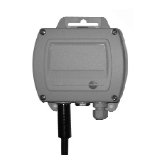
- Page 1 Flow transmitter 0555 4444 / 0699 5100/1...5 Instruction manual...
-
Page 2: Imprint
This documentation is subject to the copyright of Testo AG. Reproduction and employment contrary to the justified interests of Testo AG are prohibited without the prior, written consent of the company. We reserve the right to modify technical details in the descriptions, specifications and illustrations contained in this documentation. -
Page 3: Preface / General Notes
Preface Dear Testo customer, Congratulations for choosing a Testo product. We hope that you will enjoy many years of using the product and that it will help you in your work. Please read these operating instructions carefully and familiarise yourself with the operation of the unit before putting it to use. -
Page 4: Table Of Contents
Content Imprint ..................2 Preface / General notes ............3 Content ................4 1. Fundamental safety instructions ..........5 2. Product description ..............6 3. Measuring instrument dimensions ........6 4. Advantages of the flow transmitter........7 5. Standard versions ..............7 6. Version options ..............8 7. Compensation for thermal probes ........9 8. -
Page 5: Fundamental Safety Instructions
For safety reasons, use only original spare parts from Testo. Any additional work must only be carried out by authorised personnel. Testo will otherwise refuse to accept responsibility for the proper functioning of the instrument after repair and for the validity of certifications. -
Page 6: Product Description
2. Product description The low-cost flow transmitter can be combined with the standard flow probes of the reference class (see table on page 8). Vane, hot ball and hot wire probes can be connected. The device will then be configured for all standard applications in heating, ventilation and air-conditioning. -
Page 7: Advantages Of The Flow Transmitter
4. Advantages of the flow transmitter - Optimal price/performance ratio - electronics immune to interference thanks to reverse voltage protection, surge protection, EMC to industrial standards - Electrical isolation between supply voltage and analogue output - Standard flow sensors can be connected - Easy to install - Flexible analogue outputs and scaling - Two analogue outputs (1 - flow and 2 - temperature (optional)) -
Page 8: Version Options
6. Version options Art. No. Designation Measuring range Accuracy Permanent con- nection possible? 0635 9443* Vane probe 12 mm 0.6...20 m/s ±(0.2 m/s ±1% of reading) 0635 9540* Vane probe 16 mm 0.4...60 m/s ±(0.2 m/s ±1% of reading) with TE type K -30...+ 140 °C 0635 9440* Vane probe 60 mm 0.25...20 m/s... -
Page 9: Compensation For Thermal Probes
7. Compensation for thermal probes Testo calibrates the thermal Local altitude Average Correction probes at a reference pressure of air pressure factor 1013 hPa. If the ambient or (hPa) process pressure in the particular 1013 1.00 application differs from the 1007.01... -
Page 10: Configuration Of Connections
8. Configuration of connections RS232 connection for service software or display (optional) Solder bridge for 0...20 mA or 4...20 mA Open: = 4...20 mA Solder bridges for voltage output 0...1 V / 0...10 V Standard 4...20 mA Programming interface (for service only) Supply connection and analogue outputs Probe connection... -
Page 11: Connection
In the 4-wire system the device is supplied via a separate voltage supply (24 V DC). The outputs then actively supply the respective current or voltage signal. In the testo flow transmitter the power supply is galvanically isolated from the analogue outputs. 9.2 Current/voltage measurement (4-wire system) For other 24 V DC max. -
Page 12: Troubleshooting
10. Troubleshooting If faults occur which are not described here, please consult Testo’s customer service department (see customer service address). Faults when switching on: Fault Possible causes Remedy Currents < 3.8 mA Sensor breaks Have Testo replace the sensor (for 4...20 mA version) -
Page 13: Technical Data
11. Technical data General EMC: as per Directive 2004/108/EC Housing: Material: ABS, grey RAL 7035 Current consumption: 50...150 mA (depending on Size: 130 x 105 (140) x 52 mm connected probe) Screw connections: M 16 x 1.5 All data relate to an ambient temperature of 22 °C. Electrical connections 2 x 4 pole screwed plug in connector... -
Page 14: Accessories
12. Accessories Designation Art. No. Desktop mains unit 90...264 V AC - 24 V 800 mA 0554 1748 Top-hat rail mains unit 90...264 V AC - 24 V 3 A 0554 1749 Magnetic probe holder for vane probes 0554 0430... - Page 16 AG Postfach 11 40, D-79849 Lenzkirch Testo-Straße 1, D-79853 Lenzkirch Phone: +49 (0) 7653 681-0 Fax: +49 (0) 7653 681-100 E-mail: info@testo.de Internet: http://www.testo.com 0973.4010 de 01...


Need help?
Do you have a question about the 0555 4444 and is the answer not in the manual?
Questions and answers