Table of Contents
Advertisement
Quick Links
Advertisement
Table of Contents

Related Manuals for TDSi EXcel4


Summary of Contents for TDSi EXcel4
- Page 1 EXcel Controller User Manual UM0012, Issue 8...
- Page 2 Copyright © 2003 Time and Data Systems International Ltd (TDSi). This document or any software supplied with it may not be used for any purpose other than that for which it is supplied nor shall any part of it be reproduced without the prior written consent of TDSi. Trademarks Microsoft and Windows are registered trademarks of Microsoft Corporation.
-
Page 3: Table Of Contents
For documentation on How to use the EXgarde Toolkit..30 Testing the installation Installer mode ......................31 Reset (simply link jumper 1 and remove) ..........33 Firmware ........................33 How to upgrade EX series ACU with new Firmware ....... 33 3.4.1 Firmware Update ..................... 35 EXcel4 Controller Page i... - Page 4 Compliance Notices Compliance with CE regulations ..............46 Limitations on the intended operating environment....46 FCC Regulations Notice ..................47 ......................47 ....................48 ..........................48 ..........................48 ..............48 ........49 ..................... 49 ......................49 EXcel4 Controller Page ii...
- Page 5 Figure 18 - Communication channels ................28 Figure 19 - Selected channel ..................29 Figure 20 - Xinstall window ..........Error! Bookmark not defined. Figure 21 - Firmware loading ...........Error! Bookmark not defined. Figure 22 - ACU UID ......................42 EXcel4 Controller Page iii...
-
Page 7: Introduction
32/16 boards relays (I/O) Readers: Readers: TDSi Infra-red MICROcard (EXcel 4 requires TDSi Infra-red MICROcard, mag-stripe digital output reader), mag-stripe track 2 track 2 ABA, Wiegand 26-bit, Wiegand 34 ABA, Wiegand 26-bit, Wiegand 34 bit, bit, Wiegand 37 bit, Octopus 44 bit, Me... -
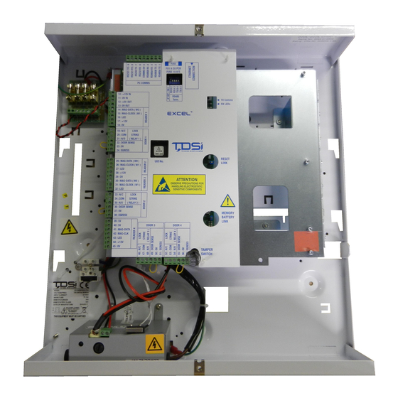
Page 8: Layout Of Ex-Series Access Control Units
Number begins with 4 e.g. 4-xxx-xxx-xxx Earth connection Power Supply Unit Fused Mains Terminal Block Space For Standby Battery (not supplied) Standby battery connection cables Tamper Switch with Spring Memory Battery Link Cable Screen Braid Earthing Clamps Reset Link EXcel4 Controller Page 2... -
Page 9: System Capabilities - Excel
EXcel is a four-door access control unit (ACU) that is administered by a computer (PC) running TDSi’s EXgarde software. More than one controller can be administered simultaneously from one or more computers, and TDSi manufacture several controller types besides EXcel that can co-exist in a single system. -
Page 10: Technical Specification Excel 4
390 x 410 x 90 mm Weight 5.7 kg (unpacked) Door/Control Relay Changeover volt-free contact 30 V, 2 A rating Ethernet 10Base-T or 100Base-Tx (Auto-Switching), RJ45, TCP/IP Communications with indication LEDs for 10Base-T connection, T-Base-TX connection, link and activity EXcel4 Controller Page 4... -
Page 11: Cable Specifications
5002-1781 Digital IR 5002-1791 OS6C24/Alpha 5096/BICC H8124 150m Screened Alarm Cable 150m Belden 9730 150m 5002-0433 5002-0434 Belden 9503 150m 5002-0435 MIFARE / 5002-0436 OS6C24/Alpha 5096/BICC H8124 150m EXsmart2 5002-0440 5002-0441 5002-0442 Screened Alarm Cable 150m EXcel4 Controller Page 5... - Page 12 When using an EX9520R converter or USB to serial converter configured to 2-wire mode, a maximum cable length of 500m is possible. Use of an MA45 converter or USB to serial converter configured for 4-wire mode will allow distances of up to a maximum of 1200 m to be achieved. EXcel4 Controller Page 6...
-
Page 13: Installation
The load output features full electronic short circuit protection under mains operation. LED’s are provided to indicate mains present and fault conditions. A single 12 v lead acid battery is required – Yuasa, 12v, 7Ah type, or similar. EXcel4 Controller Page 7... -
Page 14: Installation Do's And Don'ts
In particular note that the use of an exit (egress) button may not be legal. Single– action exit may be required. The use of shielded cable, and adherence to correct grounding procedures, is necessary for every connection to the controller. EXcel4 Controller Page 8... -
Page 15: Terminating Screened Cable At The Acu
The following two diagrams show correct methods of grounding cable shields, where the peripheral equipment may or may not be connected to ground already. Figure 2 - Peripheral mounted in Non-Metal surface Figure 3 - Peripheral mounted on Metal surface EXcel4 Controller Page 9... -
Page 16: How To Terminate
Figure 4 - Incorrect Screening Method (Tails Left Long) Figure 5 - Correct Screening Method (Tails Kept Short) EXcel4 Controller Page 10... -
Page 17: Readers
The following section covers the most popular readers currently supplied by TDSi. For any other reader, please refer to the documentation that came with the reader. - Page 18 The Reader LED default is set to bi-colour. (This can be reprogrammed to Red Only.) The LED line is held at approximately 5V, and in normal mode will pulse to 0 Volts every 2 seconds (red LED). Upon access granted this will activate to 12 Volts for 5seconds (Green). EXcel4 Controller Page 12...
-
Page 19: Power Supply For Locks
DC lock strikes must be fitted with suppression components i.e. diode plus capacitor or MOV device (Metal Oxide Varistor). AC lock strikes must be fitted with a suitable specialised suppressor, the TDSi suppressor provided is specialized and supports both AC and DC locks - part number 4262-0095. -
Page 20: Figure 6 - Suppressor
Figure 6 - Suppressor EXcel4 Controller Page 14... -
Page 21: Fail-Locked
Door 1 Lock relay Common pole Door 2 Lock relay n/c Door 2 Lock relay Common pole Door 3 Lock relay n/c Door 3 Lock relay Common pole Door 4 Lock relay n/c Door 4 Lock relay Common pole EXcel4 Controller Page 15... -
Page 22: Fail-Open Drawing (Less Than 2A Lock)
Lockstrike Relay n/c Relay pole Relay pole Relay n/o pole Coil Cable screen must NOT be connected to controller chassis if lock Power is grounded Supply Suppressor Lock release Figure 9 - DC lock release diagram EXcel4 Controller Page 16... -
Page 23: Door Sensors
0V (for Inputs 3 & 4) 1 Door Input 4 Input 5 0V (For inputs 5 & 6) 1 or 2 Door Input 6 Input 7 0V (For inputs 7 & 8) 1, 2 or 3 Door Input 8 EXcel4 Controller Page 17... -
Page 24: Supervision Options
RS485 is not supplied by the Converter then use dip switches on ONE EXpert only in the RS485 daisy chain to provide termination. Termination can be put on the first ACU in the RS485 line EXcel4 Controller Page 18... -
Page 25: Communications
It is important to screen the cable at one end only. There are several possible methods for connecting one or more ACU’s to a computer running TDSi EXgarde software: 2.15.1 Single ACU over RS232 to a PC One ACU to a PC to a maximum of 15 meters RS232 cable. -
Page 26: Protocol Converter Usb To Rs232/Rs485 Converter
J 1 -2 J 3-4 J 5-6 J 7-8 J 9-10 J 11-12 J 13-14 LINK Refit the cover when finished. Set the rear external row of 4 dip switches to Full Duplex 4 RS485 wire EXcel4 Controller Page 20... -
Page 27: Figure 11 - Rs485 Communication Diagram
Connect to the EX series ACU’s as follows: USB Converter terminal Rs485 4 WIRE Continuation of daisy block Ex Series ACU chain to other EX series Connector controllers No Connection No Connection Figure 11 - RS485 communication diagram EXcel4 Controller Page 21... -
Page 28: Ethernet Communications
EXcel . The ferrite sleeve is supplied with the EXcel and must be installed as close as possible to the end of the lead: EXcel4 Controller Page 22... -
Page 29: Built In Tcp/Ip Xport As Converter
RS485A TX RS485B TX RS485A RX RS485B RX ACU chassis ACU chassis Protective screen Below is an example of multiple ACU’s of differing TDSi types on an Ethernet and then converted to RS485 4 wire protocol. EXcel4 Controller Page 23... -
Page 30: Figure 13 - Tcp/Ip Connection Setup
Figure 13 - TCP/IP Connection setup EXcel4 Controller Page 24... -
Page 31: Pc Communications Set-Up
If you install EXgarde Software this EXgarde toolkit will be installed in the default location of C:/Program Files/TDSi/Extras/EXgarde Toolkit and in this folder is the xsearch folder. Alternatively this EXgarde Toolkit folder can be found on either the EX series Documentation CD (provided with every EX series Controller) or on the EXgarde Pro CD;... -
Page 32: Figure 15 - Com Port Select
“B” allow you to select the Base or Starting UID number to search from i.e. Type the last 9 digits only e.g. 004-003-655. The search will start from this number. “N” allow you to select the number to search on from the starting number selected with “B”. EXcel4 Controller Page 26... -
Page 33: How To Assign An I/P Address
For a more detailed description on how to use xsearch, refer to the EXgarde Toolkit manual UM0062. Located on your EX series Documentation CD or installed with EXgarde Software on your PC, location C:/Program Files/TDSi/Documentation/. 2.18.2 How to assign an I/P address Copy and paste the xsearch.exe utility tool onto the communications PC... -
Page 34: Figure 18 - Communication Channels
Figure 18 - Communication channels EXcel4 Controller Page 28... -
Page 35: Troubleshooting Tc/Ip
Installer and Telnet are other methods which may help you. For further help refer to other TDSi I/P documentations such as “How to Correctly Set UP IP Connections of TDSI Product located on your EX series Documentation CD or installed with EXgarde Software on your PC, location C:/Program Files/TDSi/Documentation/. -
Page 36: For Documentation On How To Use The Exgarde Toolkit
2.18.5 How to use the EXgarde Toolkit. Refer to the EXgarde Toolkit manual UM0062 l ocated on your EX series Documentation CD or installed with EXgarde Software on your PC, location C:/Program Files/TDSi/Documentation/. EXcel4 Controller Page 30... -
Page 37: Testing The Installation
9. Present the card again – relays 1 and 2 should be energised for 5 seconds. (At this stage, the EXpert has not been told whether it is a one-door or two-door installation). Note that until the first card is programmed using EXgarde, ANY card of the correct technology will trigger both relays. EXcel4 Controller Page 31... - Page 38 You can test all the readers, reader ports, relays and locks (if fitted) are working. To come out of installer mode, just validate your first card using the software or EXkeypad or perform a RESET EXcel4 Controller Page 32...
-
Page 39: Reset (Simply Link Jumper 1 And Remove)
2. Place Jumper on Reset J1 3. Power Up (this will be confirmed by beeping) 4. Press and continue to hold the tamper switch on. 5. Remove jumper & replace again within 15 seconds. 6. Release tamper switch 7. Power down EXcel4 Controller Page 33... - Page 40 The unit is now ready to have new firmware loaded. This can be confirmed using the EXkeypad on an EXpert which displays “LOADER Vx-xx” or one of the EXgarde toolkit utilities on an EXcel which will display either “Loader” or the short form “ldr”. EXcel4 Controller Page 34...
-
Page 41: Firmware Update
NOTE. If you are using IP it is recommended to be connected from your computer to the ACU with a crossover cable. Although the procedure can be done over a network, extreme caution on downloading the file to the correct ACU and guaranteeing a continuous seamless network connection is necessary EXcel4 Controller Page 35... -
Page 42: Trouble-Shooting
Lack of suppression across peripheral equipment containing a coil, may induce back EMF (spikes) which could potentially affect the PCB and thus erase programming in the RAM. Such effects can cause permanent damage to the circuit. Page 36 EXcel4 Controller 06.28.06.19... -
Page 43: Controller Is Alarming - Buzzing
Door Lock 1 has a built in Local door alarm (buzzer), which if the contact is left open for more than 15 seconds will “sound” out. To stop the buzzer change the door sensor type (close to open); fit a link, or simply close the door. EXcel4 Controller Page 37... -
Page 44: Reader Problems
Reader Gone, or Reader Back: This implies the reader was disconnected, or reconnected, either on the power supply lines, or on the data signal lines. Check the wiring, reader EXcel4 Controller Page 38... - Page 45 &/or check the connections at the ACU or any additional connector blocks or cable extension joints along the wiring EXcel4 Controller Page 39...
-
Page 46: Interpretation Of Xkdx Messages
Location Reader 1 Card type can be of type: Access result can be of type: K= Pin Only A= Access granted M= MICROcard (i.e. TDSi-technology B= ID not in memory card) C= ID not valid for door W= Wiegand D= ID expired... -
Page 47: Intermittently Card Works
TDSi ACUs are designed to respond only to open and closed states from a lock. When a monitored contact is connected to the Door Sense contact in a TDSi ACU, then the door is seen to open as soon as the maglock is powered down and so the lock power is immediately restored before anyone has had time to enter. -
Page 48: Identifying Versions Of Hardware
The Version 2 hardware has a UID SQUARE processor chip + a WSI processor SQUARE chip next to it. 4.2 Final configuration Final configuration involves using EXgarde to program the required features into EXcel Please refer to the help system in EXgarde for further guidance. EXcel4 Controller Page 42... -
Page 49: Connection Tables
EXcel 4 No connection 5.1.3 Connecting one EXcel to another (the same pin connections apply for all EX series) EXcel EXcel 5.1.4 RS232 to EXcel PC 9-way PC 25-way EXcel 4 terminal Function Receive Transmit Ground EXcel4 Controller Page 43... -
Page 50: Readers And Doors
Input 6 (2 or 3-door configuration) Door 4 Lock relay n/c Door 4 Lock relay Common pole Relay 4 (1, 2 or 3-door configuration) Door 4 Lock relay n/o Door 4 Door Sense Input 7 (2 or 3-door configuration) EXcel4 Controller Page 44... - Page 51 0V (for Door Sense and Egress) Door 4 Egress Input 8 (2 or 3-door configuration) EXcel4 Controller Page 45...
-
Page 52: Compliance Notices
TDSi exercise due diligence to ensure that its equipment is suitable for use in the stated applications, but ultimate responsibility for the compliance of a complete system must rest with the prime contractor at a site where local conditions may require additional EMC precautions to be taken. -
Page 53: Fcc Regulations Notice
Le présent appareil numérique n’émet pas de bruits radioélectriques dépassant les limites applicable aux appareils numériques de la Classe B prescrites dans le règlement sur le brouillage radioélectrique édicte par le Ministère des Communications du Canada. EXcel4 Controller Page 47... - Page 54 7 Safety Notices 7.1 Product description These notes apply to TDSi EXcel Access Control Units with an internal ACU PSU mains power supply fitted. The mains supply must be connected to the equipment by a permanently connected wiring installation as described below.
- Page 55 7.5 Connecting signal wiring to associated equipment. The TDSi EXcel Access Control Units with an internal AC PSU mains power supply fitted must be connected to other equipment forming part of an overall control system using signal wiring connections made with screened cable with the screen securely...
- Page 56 IN/OUT Reader 1 RS485 Chips Door 1 Processor and UID Reset Jumper Reader 2 Reader 3 Flash EPROM Memory Battery Door 2 Memory Battery Jumper Reader 4 Buzzer Tamper Switch (without spring) Door 3 Door 4 EXcel4 Controller Page 50...
- Page 57 TDSi UK Unit 10 Concept Park, Innovation Close, Poole, Dorset BH12 4QT United Kingdom t: +44 (0)1202 723535 f: +44 (0)1202 724975 e: sales@tdsi.co.uk TDSi France Immeuble ATRIA, 2 rue du Centre, 93160 NOISY LE GRAND France t: +33 (0)1 58 84 20 90 f: +33 (0)1 58 84 20 91 e: tdsif@wanadoo.fr...
Need help?
Do you have a question about the EXcel4 and is the answer not in the manual?
Questions and answers