Table of Contents
Advertisement
Advertisement
Table of Contents

Related Manuals for Eaton DX RT 6K UPS


Summary of Contents for Eaton DX RT 6K UPS
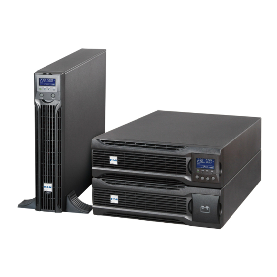
- Page 1 Eaton DX RT Online UPS 6000/10000VA(XL) IN USER MANUAL...
-
Page 3: Service And Support
Service and support Call your local service representative Safety Instructions SAVE THESE INSTRUCTIONS. This manual contains important instructions that should be followed during installation and maintenance of the UPS and batteries. The UPS models that are covered in this manual are intended for installation in an environment within 0 to 50°C, free of conductive contaminant. -
Page 4: Safety Of Persons
Safety of persons RISK OF VOLTAGE BACKFEED. The system has its own power source (the battery). Isolate the UPS and check for hazardous voltage upstream and downstream during lockout-tagout operation. Terminal blocks may be energized even if the system is disconnected from the AC power source. -
Page 5: Special Precautions
Disconnection and overcurrent protection devices shall be provided by others for permanently connected AC input (Normal AC/Bypass AC) and AC output circuits. Check that the indications on the rating plate correspond to your AC powered system and to the actual electrical consumption of all the equipment to be connected to the system. For PLUGGABLE EQUIPMENT, the socket-outlet shall be installed near the equipment ... -
Page 6: Table Of Contents
Contents ...................... 1 1. Introduction 1.1 Environmental protection......................1 1.2 Electronic equipment protection ....................2 ...................... 3 2. Presentation 2.1 RT Front panel ........................... 3 2.2 RT Rear panels .......................... 3 2.3 EBM Front panel: ........................4 2.4 EBM rear panel: ......................... 4 2.3 Circuit diagram........................... - Page 7 6.2 Intelligent Card (Optional) ...................... 34 6.3 UPS Management Software ....................34 .................... 35 7. UPS maintenance 7.1Equipment care......................... 35 7.2 Transporting the UPS ......................35 7.3 Storing the equipment......................35 7.4 Replacing batteries ......................... 36 7.5 Recycling the used equipment ....................37 ....................
-
Page 8: Introduction
1. Introduction Thank you for selecting UPS to protect your electrical equipment. The UPS has been designed with the utmost care. We recommend that you take the time to read this manual to take full advantage of the many features of your UPS (Uninterruptible Power System). Before installing your UPS, please read the booklet presenting the safety instructions. -
Page 9: Electronic Equipment Protection
Battery The product contains lead-acid batteries that must be processed according to applicable local regulations concerning batteries. The battery may be removed to comply with regulations and in view of correct disposal. 1.2 Electronic equipment protection The uninterruptible power system (UPS) protects your sensitive electronic equipment from the most common power problems, including power failures, power sags, power surges, brownouts, line noise, high voltage spikes, frequency variations, switching transients, and harmonic distortion. -
Page 10: Presentation
2. Presentation 2.1 RT Front panel 2.2 RT Rear panels 1. Intelligent slot bat-, and no external battery connector #10.) 2. USB 9. Input switch 3. RS232 10. External battery connector 4. RJ11 (only for RT model) 11. Maintenance bypass switch 5. -
Page 11: Ebm Front Panel
2.3 EBM Front panel: 2.4 EBM rear panel: RT EBM 13. Fuse board cover (replace EBM fuse) 14. EBM plug 15. EBM connector 2.3 Circuit diagram... -
Page 12: Installation
3. Installation It is recommended to move the equipment to the installation site by using a pallet jack or a truck before unpacking. The system may be installed only by qualified electricians in accordance with applicable safety regulations. The cabinet is heavy, please install it with at least two peoples. 3.1 Inspecting the equipment If any equipment has been damaged during shipment, keep the shipping cartons and packing materials for the carrier or place of purchase and file a claim for... -
Page 13: Checking The Accessory Kit
Recycling symbols are printed on the packing materials to facilitate sorting. 3.3 Checking the accessory kit Verify that the following additional items are included with the unit: DXRT Eaton DX RT UPS Eaton DX RT UPS 6000VAIN/10000VAIN 6000VAXLIN/10000VAXLIN Battery power cable... -
Page 14: Install The Unit
3.4 Install the unit 3.4.1 RT model: Rack position installing This procedure is suitable for 19 inch rack cabinet installation with a minimum of 800mm depth. UPS model Identify the final position and keep ‘2U’ space for this installing. Note that you already installed a ‘rail kit’... - Page 15 3. Connect EBM to UPS with ‘Battery power cable’. Note: This ‘Battery power cable’ may have different plug according to the number of battery inside of this unit, please check the ‘Voltage ’ parameter on rear-panel if it matches the UPS before connection. The battery number can be adjusted from ‘16pcs*1 strings’...
- Page 16 2. Set up the ‘Stabilizer bracket’, then take the unit into ‘Stabilizer bracket’. EBM model 1. Set up the ‘Extension plate’ as below and install to ‘Stabilizer bracket’ from UPS. 2. Take the UPS& EBM into ‘Stabilizer bracket’ individually. 3.
-
Page 17: Power Cables Connection
4. Power cables connection Recommended protective devices and cable cross-sections Recommended upstream protection UPS power rating Upstream circuit breaker DX RT 6K UPS D curve – 63A DX RT 10K UPS D curve – 100A N(L2) To UPS Normal AC / Bypass AC source. -
Page 18: Access To Terminal Blocks (Ac Source To Ups)
4.1 Access to terminal blocks (AC source to UPS) High leakage current: Earth connection essential before connecting supply. Common input/output sources connection This type of connection must be carried out by qualified electrical personnel Before carrying out any connection, check that the upstream protection devices (Normal AC source and Bypass AC source) are open "O"... -
Page 19: Access To Terminal Blocks (Pdu Source To R/T Ups)(Optional)
4.2 Access to terminal blocks (PDU source to R/T UPS)(Optional) If you ordered PDU model, please connect the UPS’s terminal blocks from PDU’s source, detail operation please refer to PDU’s user manual. 4.3 Parallel Installation and Operation (Optional) As long as the UPS is equipped with parallel board and parallel cables, up to 3 UPSs can be connected in parallel to configure a sharing and redundant output power. - Page 20 How to install a new parallel UPS system: Before installing a new parallel UPS system, please prepare the input /output wires, breakers, and a main maintenance mechanical switch or static switch. 2) Independent battery packs for each UPS. 3) Remove the cover plate of parallel port on the UPS, connect each UPS one by one with parallel cable, and make sure the cable is screwed tightly.
- Page 21 Rack model: 6) Turn on the input breakers for the parallel UPS. 7) Pressing button continuously for more than 1 second for one UPS of the system, then the system will turn to line mode. 8) Regulate the output voltage of the each UPS separately, and check if the difference of output voltage is less than 0.5V among the parallel system.
- Page 22 2) Regulate the output voltage of the new UPS: check if the output voltage difference between the new UPS and the parallel system is less than 0.5V. 3) Ensure the bypass of the parallel system is normal and the auto bypass setting is “enable”, then press the button to turn off the UPS, the UPS will turn to bypass mode.
- Page 23 3. How to remove all the UPS from parallel system: Firstly, a main maintenance mechanical switch or static switch should be installed for the parallel system. 2) Ensure the bypass is normal and the auto bypass setting is “enable”, press button to turn off the UPS system, and the UPS system will turn to bypass mode.
-
Page 24: Operation
5. Operation 5.1 Control panel The UPS has a graphical LCD with five-button. It provides useful information about the UPS itself, load status, events, measurements and settings. The following table shows the indicator status and description: Indicator Status Description Online model The UPS is operating normally on Online or on High (Green) Efficiency mode. - Page 25 The following table shows the Control Button Functions: The Button Function Illustration Press this button for >100ms&<1s can power on Power on the ups without utility input at the condition of battery connected. When the unit is powered on and stayed is in Turn on Bypass mode, press this button for >1s can turn on the UPS.
-
Page 26: Lcd Description
The Buzzer definition as below: UPS condition Buzzer status Fault active Continuous Over Load 2 Beep every second Warning active Other Warning active Beep every second Beep every 4 seconds, if battery low, buzzer Beep every Battery output second Bypass output Beep every 2 minutes 5.2 LCD description The LCD backlight automatically dims after 2 minutes of inactivity (except UPS is... - Page 27 The following table describes the information of ups status. Note: If other indicator appears, see troubleshooting on chapter 7.2 for more information. Operation status Cause Description Standby mode The UPS is Off. UPS is operating without output. Online mode The UPS is operating The UPS is powering and protecting the normally.
-
Page 28: Display Functions
Warning There are some The UPS continues working, but please abnormal problems pay attention to the warning, or the UPS during the operation may fail. of UPS. Normally the problems are not fatal Fault Some fatal problems The UPS will cut off the output or transfer to happened bypass mode at once, and keep alarming. -
Page 29: User Settings
Reset fault status Clears active fault Clear event log Clears events Restore factory set Returns all settings to original values Settings Sets parameters Event log Event list Identification [Product type/model] / [Part/Serial number] / [UPS/NMC firmware] 5.4 User settings The following table displays the options that can be changed by the user. Submenu Available settings Default settings... -
Page 30: Ups Startup And Shutdown
External [0~20] According to model battery modules External [0~300] According to model battery AH setting Battery [enabled] [disabled] [enabled] remaining time Charger [0~4] 0~4A for standard model [1.4A] for 6K current [0~12] 0~12A for long backup model [2A] for 10K [4A] for 6KS/10KS Site wiring [disabled] [enabled]... - Page 31 Before using this feature, the UPS must have been powered by utility power with output enabled at least once. After connect the UPS with battery, should wait 10s before pressing the button for pre-charging the auxiliary power supply. Battery start can be disabled. See “Start on battery” setting in user settings refer to chapter 5.4.
-
Page 32: Lcd Operation
5.6 LCD operation Except the default UPS status summary screen, the user can get more useful information about UPS status, detailed various measurements, previous event records which ever occurred, UPS own identification, and could change the settings to fit the user own requirements, optimize the function of UPS. The main menu In the default UPS status summary screen, when pressing <300ms, the... - Page 33 The UPS status menu By pressing on the menu of “UPS status”, the display would enter the next UPS status menu tree. The content of UPS status menu tree is same as the default UPS status summary menu. By pressing ESC >300ms, the display would return the last main menu tree.
- Page 34 The measurement menu By pressing on the menu of “Measurement”, the display would enter the next measurement menu tree. A lot of detailed useful information could be checked here, Ex. the output voltage and frequency, the output current, the load capacity, the input voltage and frequency, etc.
- Page 35 The event log menu By pressing on the menu of “Event log”, the display would enter the next event menu tree. All the previous events, alarm and fault have been recorded here. The information includes the illustration, the event code, and the precise time of UPS when the event happened.
- Page 36 would stop alarm and recover to bypass mode. And the reason of fault should be checked and deleted before UPS is turned on again by manual operation. Restore factory settings: all the settings would be recover to default factory settings. It could only be done in Bypass mode.
- Page 37 The identification information includes UPS serial number, firmware serial number, model type, would be shown here. By press ESC >300ms, the display would return the last main menu tree. Eaton DX RT 6Ki The setting menu Please contact your local distributor for further information before using the settings.
- Page 39 Example: set rated output voltage value Setting menu tree By press <1s The option would flash Output voltage Output voltage <230V> <230V> By press <1s By press >100ms, to select the wanted option Output voltage <220V> By press >1s, to confirm the setting The option would stop flashing Output voltage after being confirmed...
-
Page 40: Communication
6. Communication 6.1 Communication ports RS232 or USB communication ports The RS232 and USB communication ports cannot operate simultaneously. 1. Communication cable to the serial or USB port on the computer. 2. Connect the other end of the communication cable to the RS232 or USB communication port on the UPS. -
Page 41: Intelligent Card (Optional)
6.2 Intelligent Card (Optional) Intelligent Card allow the UPS to communicate with different types of devices in variety of networking environments. The Online series has one available communication bay for the following connectivity cards: 1. Connect UPS-MS Web/SNMP Card – has SNMP and HTTP capabilities as well as monitoring through a Web browser interface;... -
Page 42: Ups Maintenance
Installation procedure: 1. Go to the website: http://www.ups-software-download.com/ 2. Choose the operation system you need and follow the instruction described on the website to download the software. 3. When downloading all required files from the internet, enter the serial No: 511C1-01220-0100-478DF2A to install the software. -
Page 43: Replacing Batteries
7.4 Replacing batteries DO NOT DISCONNECT the batteries while the UPS is in Battery mode. Consider all warnings, cautions, and notes before replacing batteries. Servicing should be performed by qualified service personnel with knowledgeable of batteries and required precautions. Keep unauthorized personnel away from batteries. -
Page 44: Recycling The Used Equipment
least. For Tower module, should turn the MBS to bypass and switch off the input and then replace the EBM(s). For RT module, if PDU is connected with the UPS, should turn the MBS to bypass and switch off the input and then replace the EBM(s). If PDU is not connected with the UPS, should turn off the UPS and then replace the EBM. -
Page 45: Troubleshooting
Do not discard the UPS or the UPS batteries in the trash. This product contains sealed, lead acid batteries and must be disposed of properly. For more information, contact your local recycling/ reuse or hazardous waste center. Do not discard waste electrical or electronic equipment (WEEE) in the trash. - Page 46 Fault code: A60D Battery not connected Check the battery and battery Fault light flashes, cable. If the battery is damaged, 1 beep every 1 second. Replace it immediately by a professional. Fault code: A604 Battery voltage is too low Check the battery, If the battery Fault light flashes, is damaged, Replace it 1 beep every 1 second.
- Page 47 Fault code: F304 Indicates that the positive Please contact your supplier Fault lamp lights long, BUS voltage and Beep continuous. negative BUS voltage unbalance to fault Fault code: F304 Indicates that the positive Please contact your supplier Fault lamp lights long, BUS and negative BUS Beep continuous.
- Page 48 Fault code: A80E Power requirements Remove some of the equipment Fault LED is flash exceed the UPS capacity from the UPS. 2 beep every 1 second The UPS continues to operate, but may switch to Bypass mode or shut down if the load increases.
-
Page 49: Silencing The Alarm
Fault code: A004 Alarm because of UPS Please contact your supplier Fault LED is flash internal heat sink 1 beep every 1 second temperature is too high. Fault code: A004 Alarm because of Check if the ambient Fault LED is flash ambient temperature temperature exceed 50°C. -
Page 50: Specifications
Table 2. Extended Battery Module model list Model Configuration Battery voltage For power ratings 192Vdc (7Ah) 6000-10000VA Eaton DXRT EBM 192-07 RT3U IN 192Vdc (9Ah) 6000-10000VA Eaton DXRT EBM 192-09 RT3U IN Table 3. Weights and dimensions Description Weights (kg) - Page 51 176~276Vac Noise filtering MOV for normal and common mode noise Model Default input Voltage at 100% Load (Voltage/Current) 230V/31.2A 176~276Vac Eaton DX RT 6000VAIN 230V/38.7A 176~276Vac Eaton DX RT 6000VAXLIN 230V/49.9A 176~276Vac Eaton DX RT 10000VAIN 230V/57.6A 176~276Vac Eaton DX RT 10000VAXLIN Table 5.
- Page 52 * for 208V output, the load level will be derating to 90%. Table 7. Electrical output connections Model Output connection Output cable Eaton DX RT 6000VAIN Eaton DX RT 6000VAXLIN Hardwired Not provided Eaton DX RT 10000VAIN Eaton DX RT 10000VAXLIN Table 8.
- Page 53 Operating altitude Up to 3,000 meters (9,843 ft) above sea level with 10% derating per 1000m Transit altitude Up to 10,000 meters (32,808 ft) above sea level Audible noise < 50 dBA at 1 meter typical for 6kVA models < 55 dBA at 1 meter typical for 10kVA models Table 9.
-
Page 54: Glossary
10 Glossary Bypass AC source Source supplying the bypass line. The equipment can be transferred to the bypass line if an overload occurs on the UPS output, for maintenance or in the event of a malfunction. Frequency converter Operating mode used to convert the AC-power frequency between the UPS input and output (50Hz ->... - Page 56 614-02180XT1...
Need help?
Do you have a question about the DX RT 6K UPS and is the answer not in the manual?
Questions and answers