Sign In
Upload
Download
Table of Contents
Contents
Add to my manuals
Delete from my manuals
Share
URL of this page:
HTML Link:
Bookmark this page
Add
Manual will be automatically added to "My Manuals"
Print this page
×
Bookmark added
×
Added to my manuals
Manuals
Brands
Eaton Manuals
UPS
Pulsar EX RT 5000
Installation and user manual
Eaton 5000 RT Installation And User Manual
Pulsar series
Hide thumbs
Also See for 5000 RT
:
Quick manual
(4 pages)
1
2
3
4
Table Of Contents
5
6
7
8
9
10
11
12
13
14
15
16
17
18
19
20
21
22
23
24
25
26
27
28
29
30
31
32
33
34
35
36
37
38
39
40
41
42
43
44
page
of
44
Go
/
44
Contents
Table of Contents
Troubleshooting
Bookmarks
Table of Contents
Revision History
Table of Contents
Introduction
Important Safety Instructions
Symbol Usage
1 Presentation
Standard Positions
Rear Panels
Display and Control Panel
Accessories for Rack Mount
Extended Battery (EXB)
2 Installation
Unpacking and Contents Check
Internal Batteries Connection (Battery Start-Up)
Installation in Tower Position
Installation in Rack Position
Communication Ports
Required Protective Devices and Cable Cross-Sections
Hardwire Connection of Output Power Cable to UPS
Connection to Output Receptacles
Connection of Extended Battery Module, UPS, and Transformer
3 Operation
Initial Start-Up
Final Start-Up Sequence
Operating Modes
Operation on Battery Power
Return to Normal AC Source
UPS Shutdown When AC Present
UPS Shutdown When on Battery
4 Access to Maintenance and Personalization Data
Display Organization
Access to Measurements
Access to UPS Set-Up and Maintenance Using the Control Panel
UPS Set-Up
Maintenance
Personalization Using External Software
5 Troubleshooting
Troubleshooting LEDS (21) and (22)
Troubleshooting Not Requiring EATON
Troubleshooting Requiring EATON After-Sales Support
6 Life Cycle Monitoring (LCM)
Description
7 Maintenance
Hot Swapping the Power Sub-Module
Hot Swapping the Battery Sub-Module
8 Appendices
Technical Specifications
EATON Customer Care Center
Technical Support and Product Services
Who to Contact
Scheduling Field Service Engineer Support
Return Policy for Repair of Single Phase Products (RGA)
Glossary
Advertisement
Quick Links
1
Internal Batteries Connection (Battery Start-Up)
2
Troubleshooting Leds (21) and (22)
3
Hot Swapping the Battery Sub-Module
Download this manual
w w w . e a t o n . c o m
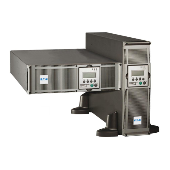
MX
5000 RT — UPS
EXB RT — Extended
Battery
Transformer 5000
Installation and User Manual
Pulsar Series
Table of
Contents
Previous
Page
Next
Page
1
2
3
4
5
Advertisement
Table of Contents
Troubleshooting
Troubleshooting
31
Troubleshooting Requiring EATON After-Sales Support
32
Need help?
Do you have a question about the 5000 RT and is the answer not in the manual?
Ask a question
Questions and answers
Related Manuals for Eaton 5000 RT
UPS Eaton Eaton EX RT Quick Manual
Pulsar series (4 pages)
UPS Eaton MX 4000 RT Installation And User Manual
Eaton mx range pulsar series ups (32 pages)
UPS Eaton MGE Pulsar MX 4000 RT Firmware Update
(12 pages)
Control Unit Eaton Transformer 5000 Quick Start
(4 pages)
UPS Eaton EX 2200 RT 2U Installation And User Manual
Pulsar series (172 pages)
UPS Eaton EX 2200 RT 2U Installation And User Manual
Pulsar series (132 pages)
UPS Eaton EX Pulsar Series Installation And User Manual
(66 pages)
UPS Eaton EX 2200 RT 3U Installation And User Manual
(172 pages)
UPS Eaton Pulsar EX RT Series Brochure & Specs
Pulsar ex rt series 7/11 kva single phase input / single phase output 5/7/11 kva three phase input / single phase output (2 pages)
UPS Eaton EX RT 5 Quick Start Manual
(13 pages)
UPS Eaton EX RT 5 Installation And User Manual
(38 pages)
UPS Eaton EX RT EXB 7 Installation And User Manual
(233 pages)
UPS Eaton RT 1250VA User Manual
(35 pages)
UPS Eaton 700VA User And Installation Manual
(19 pages)
UPS Eaton Evolution S EXB 2500 RT 3U Installation And User Manual
Pulsar series (158 pages)
UPS Eaton DX RT 6K UPS User Manual
6000/10000va(xl) in online ups (56 pages)
This manual is also suitable for:
Exb rt
Mx 5000 rt
Mx exb rt
Transformer 5000
Table of Contents
Print
Rename the bookmark
Delete bookmark?
Delete from my manuals?
Login
Sign In
OR
Sign in with Facebook
Sign in with Google
Upload manual
Upload from disk
Upload from URL


Need help?
Do you have a question about the 5000 RT and is the answer not in the manual?
Questions and answers