Lincat Opus 800 Series User, Installation, Servicing And Conversion Instructions
Gas chargrills
Hide thumbs
Also See for Opus 800 Series:
Table of Contents
Advertisement
User, Installation, Servicing and Conversion
Instructions
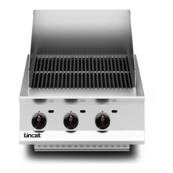
Opus 800 Gas Chargrills
OG8401, OG8402 & OG8403
Please make a note of your product details for
future use:
Date Purchased:_________________________
Model Number:__________________________
Serial Number:__________________________
Dealer:_________________________________
_______________________________________
IS589 ECN4504
1
Advertisement
Table of Contents

Related Manuals for Lincat Opus 800 Series


Summary of Contents for Lincat Opus 800 Series
- Page 1 User, Installation, Servicing and Conversion Instructions Opus 800 Gas Chargrills OG8401, OG8402 & OG8403 Please make a note of your product details for future use: Date Purchased:_________________________ Model Number:__________________________ Serial Number:__________________________ Dealer:_________________________________ _______________________________________ IS589 ECN4504...
-
Page 2: Customer Information
CAUTION! This is a Caution symbol. This symbol is used throughout the user guide whenever there is a risk damaging your Lincat product. Ensure that these warnings are read and understood at all times. NOTE: This is a Note symbol. This symbol is used throughout the user guide to provide additional information, hints and tips. -
Page 3: Table Of Contents
CONTENTS Contents Page Customer Information………………………………………………………. 2 Warnings and Precautions………………………………………………… 3 Technical Data……………………………………………………………….. 4 Commissioning………………………………………………………………. 5 Check List of Enclosures………………………………………………….. 5 Installation…………………………………………………….……………… 6-7 Conversion of Gas Types………………………………………………….. 8-10 User…………………………………………………………………………….. 11-12 Servicing ……………………………………………………………………… 13 Component Replacement ………………………………………….……… 14 Spare Parts List……………………………………………………………… 15 Fault Finding…………………………………………………………………. -
Page 4: Technical Data
TECHNICAL DATA Model OG8401 OG8402 OG8403 Dimensions Overall Height (mm) Width (mm) 1200 Depth (mm) Weight (kg) Cooking Surface w x d (mm) 500 X 620 700 X 620 1100 X 620 Cooking Grid Area (m 0.31 0.43 0.68 Heat Input Total Heat Input Natural (Gross) 13.8kW 23kW... -
Page 5: Commissioning
Male – Female Elbow Pressure Regulator SERIAL NUMBER Each appliance manufactured at Lincat has a unique identifying number found in the NOTE top right hand corner of the data plate attached at the rear of the appliance. Please record that number in the space provided should it be required for future reference. -
Page 6: Installation
INSTALLATION SITING The installer must ensure that all local regulations in force are met and that there is an unobstructed minimum distance of 1000mm from the top of the cooking grid to the extraction canopy, which must be of non-combustible material. The appliance should be installed on a level surface ensuring the unit is stable and firmly located. - Page 7 SUPPLY AND OPERATING PRESSURES The appliance is connected directly to the gas supply where the gas supply pressure is controlled at the source of inlet in the building or via the regulator attached to bottled gases. Natural gas appliances are connected directly to the gas supply provided the inlet pressure is regulated up stream to 20mbar.
-
Page 8: Conversion Of Gas Types
CONVERSION OF GAS TYPES CONVERSION OF GAS TYPE Burner Injector Changes Inlet Part Model Mark Pressure Number 20mbar 1.51 JE45 37mbar 1.06 JE34 Valve Bypass Injector Changes Part When converting to Propane an external Model Mark Number regulator must be fitted to the appliance gas inlet in conjunction with a barrel nipple and or ½”... - Page 9 Pilot Injector Removal Remove the fascia panel as detailed previously to gain access to the valves and pilot assemblies. JExx To change the pilot injector very carefully loosen the ignitor retaining nut A and withdraw the ignitor B Loosen and the pilot feed pipe nut C and withdraw the pilot feed pipe from the pilot assembly The pilot injector, JExx, can be removed and replaced with the appropriate injector applicable to gas type Refit the pilot feed pipe and secure nut C Refit the ignitor B...
- Page 10 Remove the injector JEx together with the fibre washer (if applicable) and the copper washer W Replace with the new injector applicable to the gas type being converted with a new copper washer, the injector should be tightened to 2.5Nm and the thread should have a 0.5mm covering of Loctite 577. Refit the bracket Tighten the burner feed pipe nut Check connections are leak free...
-
Page 11: User
USER INSTRUCTION APPLIANCE USE This appliance is only for professional use and should only be used by qualified personnel. Ensure that the person responsible understands how to light, safely operate, clean and shut down the appliance and is made aware of the position and operation of the gas isolating cock in the event of an emergency. - Page 12 If the pilot flame goes out repeat the process until the flame is maintained. Leave the pilot lit for a further 45-60 seconds to allow the flame failure sensing element to heat to its full potential. To light the gas at the corresponding burner rotate the control knob to any point between the low rate and full rate as denoted by the small and large stylized flames on the control knob.
-
Page 13: Servicing
The only end user service operation permitted is the routine cleaning and inspection of external parts of the appliance. The only maintenance operation permitted is the replacement of parts by approved and qualified representatives appointed by Lincat Ltd. Visual inspection shall determine that: ... -
Page 14: Component Replacement
COMPONENT REPLACEMENT Valve Body Loosen the pilot feed pipe nut AA and withdraw the pilot feed pipe from the valve body Loosen the valve inlet nut BB Loosen the burner feed pipe nut CC and free the burner feed pipe from the valve body Loosen the valve body nut DD Loosen and remove the thermocouple nut EE (not shown) at the rear of the valve Disconnect the ignitor lead from the ignitor at the pilot assembly (not shown) -
Page 15: Spare Parts List
SPARE PARTS LIST Part number Part description Used on BP45 Cast Branding Grid BU29/S Ceramic Plaque Burner CO113 Copper Washer CO248 Olive 8mm CO254 Tube Nut CO52 Stud Elbow 8mm CO53 Lock Nut FE40 Adjustable Foot IG03 Ignitor Electrode IS571 User Manual JE136 Bypass Injector Natural Gas... -
Page 16: Fault Finding
FAULT FINDING User Fault Finding Pilot not lighting Check gas supply is on Turn on the gas supply Gas supply is on but pilot not lighting Check for spark at ignitor The spark can be seen by looking through the inspection slots on the control panel. -
Page 17: Service Information
Gas Appliance Regulations 2016/426. GUARANTEE This unit carries a comprehensive UK mainland warranty. The guarantee is in addition to, and does not diminish your statutory or legal rights. Contact Lincat for terms and conditions The guarantee does not cover: Accidental damage, misuse or use not in accordance with the manufacturer’s instructions ... - Page 18 IS589 ECN4504...
- Page 19 IS589 ECN4504...
- Page 20 IS589 ECN4504...
Need help?
Do you have a question about the Opus 800 Series and is the answer not in the manual?
Questions and answers