
Related Manuals for Nidec LEROY-SOMER Commander ID30 Series


Summary of Contents for Nidec LEROY-SOMER Commander ID30 Series
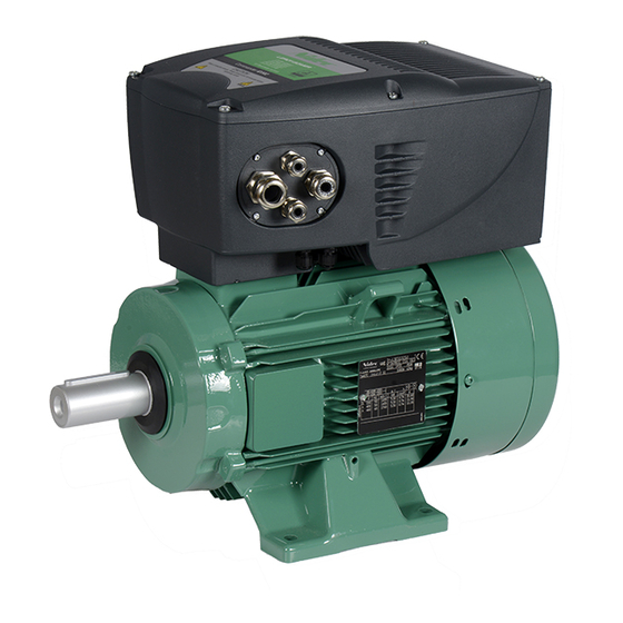
- Page 1 Installation and quick start commissioning guide Commander ID300/302 Integrated drive for IMfinity ® motors with or w/o brake Reference : 5511 en - 2017.06 / a...
- Page 2 NOTE LEROY-SOMER reserves the right to modify the characteristics of its products at any time in order to incorporate the latest technological developments. The information contained in this document may therefore be changed without notice. WARNING For the user’s own safety, the Commander ID300/302 must be connected to an approved earth ( terminal If accidentally starting the installation is likely to cause a risk to personnel or the machines being driven, it is essential to supply the equipment via a circuit-breaking device (power contactor) which can be controlled via an external safety system (emergency stop, detection of errors on the installation).
- Page 3 SAFETY AND OPERATING INSTRUCTIONS FOR VARIABLE SPEED DRIVES (In accordance with the low voltage directive 2014/35/EU) 4 - Installation Throughout the manual, this symbol warns The installation and cooling of equipment must comply of consequences which may arise from with the specifications in the manual supplied with the inappropriate product.
-
Page 4: Table Of Contents
CONTENT 1 - GENERAL INFORMATION ..................5 1.1 - General operating principle ..................5 1.2 - Designation and presentation ..................5 1.3 - Environmental characteristics ..................8 1.4 - Electrical characteristics ....................9 1.5 - Earth leakage current ....................11 1.6 - Thermal overload protection and typical overload limits ..........12 1.7 - Surge immunity of control circuits ................12 1.8 - Options ........................13 2 - MECHANICAL INSTALLATION .................15... -
Page 5: General Information
GENERAL INFORMATION 1 - GENERAL INFORMATION The motor can be offered in several mounting arrangements (foot, flange) and can be combined CAUTION with standard gearboxes and brake from Leroy-Somer The characteristics given in this section are for ranges. 40 °C (104 °F), 1000 m altitude and 3 kHz swit ching frequency. - Page 6 GENERAL INFORMATION 1.2.2 - Motor nameplate IES2 Motor rated speed Motor rated (Pr 00.007) power factor (Pr 00.009) Motor rated voltage Motor rated (Pr 00.008) Motor performance ratings current Eff. (Pr 00.006) 8.45 Minimum Maximum frequency frequency for gearmotor (Pr 00.001) (Pr 00.002) Performance system Maximum frequency for...
- Page 7 GENERAL INFORMATION 1.2.4 - Commander ID300/302 presentation • Size 1 or 2 Optional Fieldbuses and I/O extension* Optional Braking Optional Resistors Keypads* Optional Fan Cable entry side flanges (2 models) LED & Command side flanges Brake Control (4 models) option External EMC filter (available soon) (*) To be mounted by the user.
-
Page 8: Environmental Characteristics
GENERAL INFORMATION 1.3 - Environmental characteristics Characteristics Level Environmental protection IP55 rating Operating ambient air • -16°C (3.2°F) to 40°C (104°F) temperature • Up to 50°C (122°F) with derating (current derating of 1% per additional Celsius degree from 40°C). For more information, please contact Leroy-Somer. Storage and transport •... -
Page 9: Electrical Characteristics
GENERAL INFORMATION 1.4 - Electrical characteristics 1.4.1 - General characteristics Characteristics Level Maximum supply imbalance 2 % negative phase sequence (equivalent to 3 % voltage imbalance between phases). Starts per hour By electronic control: unlimited By interrupting the AC supply: ≤ 20 (equally spaced) Motor frequency variation range From 10 to 150 Hz maximum. - Page 10 GENERAL INFORMATION Commander ID300/302 with IE motors Commander Supply IMfinity Motor ® ID300 drive Output Output Voltage input Current power Size Ref. 4 poles - IE2 4 poles - IE3 2 poles - IE3 current 12030 LSES 80LG LSES 80LG LSES 80L 0.75 230V...
-
Page 11: Earth Leakage Current
GENERAL INFORMATION Commander ID300/302 with non IE or IE3 motors and brake Commander Supply LS or IMfinity Motor ® ID300/302 drive Output Output Voltage input Brake Current power Size Ref. 4 poles - NIE 4 poles - IE3 current type 14012 FFB1 LS 71M... -
Page 12: Thermal Overload Protection And Typical Overload Limits
GENERAL INFORMATION 1.6 - Thermal overload protection and 2. Shielded cable with additional power ground bonding. The cable shield may be connected to ground typical overload limits at both ends, but in addition the ground conductors at both ends of the cable must be bonded together by a As standard, the Commander ID300/302 integrates power ground cable (equipotential bonding cable) with internal functions to protect motor and drive against... -
Page 13: Options
GENERAL INFORMATION 1.8 - Options Type Option Name Details ID-RUN-POT- • 1 potentiometer, connected to drive control terminal 1 LED-FLANGE to 3 • 3 command buttons, connected to drive control terminal 9 & 10: Run Forward + Run Reverse + Stop (no reset) •... - Page 14 GENERAL INFORMATION Type Option Name Details ID-SIZE1- • For size 1 and 2 drives, use ID-SIZE1-DBR200: DBR200 Resistor 200W, 200 Ω ID-SIZE3- • For size 3 drive, use ID-SIZE3-DBR400: DBR400 Resistor 400W, 100 Ω Braking Mounting arrangements: back side of the drive (new resistors drive dimensions: W = 296 x D = 140 (mm) for sizes 1 &...
-
Page 15: Mechanical Installation
MECHANICAL INSTALLATION Type Option Name Details ID-SIZE1-I/O • For size 1 and 2 drives, use ID-SIZE1-I/O Increases the I/O capability Mounting arrangement: replaces standard terminal cover (new drive dimensions: H + 41.5 mm). This option has to be mounted by the user. Please refer to the relevant mounting documentation. -
Page 16: Handling
MECHANICAL INSTALLATION 2.2 - Handling CAUTION For a brake motor, ensure there is minimum • Position of lifting rings for lifting the motor clearance (corresponding to the length of the only (not connected to the machine). cover) at the non-drive end of the brake motor •... -
Page 17: Coupling
MECHANICAL INSTALLATION 2.5 - Coupling CONFORMING MOUNTINGS Preparation Coupling adapted to the Machining of visible parts length of the key protruding from the key Turn the motor by hand before coupling to detect any possible fault due to handling. Part to be machined √... -
Page 18: Connections
CONNECTIONS 3 - CONNECTIONS of automatically isolating the plug from the drive must be used (e.g. a latching relay). • All connection work must be performed in • The STOP and the Safe Torque Off functions do accordance with the laws in force in the not remove dangerous voltages from the drive, the country where the drive is installed. -
Page 19: Terminal Block Location
CONNECTIONS 3.2 - Terminal block location Power and control terminal blocks are all removable (relay, STO, control, AC power). To avoid a fire hazard and maintain validity of the UL listing, adhere to the specified tightening torques for the power and ground terminals. •... -
Page 20: Cable Runs
CONNECTIONS • Commander ID300/302 with ID-SIZEx-Brake Contactor option (drive size 1 or 2 shown) Relay terminals EIA 485 serial comms RJ45 connector STO terminals Control terminals Small screwdriver Braking terminals Maximum torque setting: 0.5 N.m (0.37 Ib ft ) AC power terminals Philips screwdriver Ground terminals Maximum torque... -
Page 21: Power Connections
CONNECTIONS 3.5 - Power connections Max. Fuse ratings Cable size • It is compulsory to connect the motor to Mains input ID300 earth, and earthing must be performed in supply current ref. accordance with current regulations (protection of workers). 12017 •... -
Page 22: Control Connections
CONNECTIONS 3.6 - Control connections • Dedicated brake motor power connections with ID-SIZEx-Brake contactor option • The control circuits are isolated from the power circuits in the Commander ID300/302 by single insulation only. The installer must ensure that the external control circuits are insulated Optional from human contact by at least one layer of insulation braking resistor... - Page 23 CONNECTIONS 3.6.2 - Terminal characteristics Commander ID302 Control wiring +10V +10V user output Function Supply for external analog Size 1 Size 3 or 2 devices Nominal voltage 10.2 V Voltage tolerance ± 3 % +10 V 10kΩ Voltage frequency Max. output current 5 mA ADI1 reference...
- Page 24 CONNECTIONS Analog or digital input or ADIO3 +24 V analog output Default function Assigned to red, green and Function Supply for external digital yellow LEDs (flange devices options) Voltage tolerance ±20 % Resolution 11 bits Maximum output current 200 mA (total including all Sample rate 4 ms Digital Outputs).
- Page 25 CONNECTIONS 3.6.3 - Safe torque off inputs (Commander ID302 Digital input 2 only) Digital input 3 The Safe Torque Off function provides a means for preventing the drive from generating torque in the Digital input 4 motor with a very high level of integrity. It is suitable for DI2 default function - ID300: Drive enable incorporation into a safety system for a machine.
-
Page 26: Quick Start Commissioning
QUICK START COMMISSIONING 4 - QUICK START COMMISSIONING STO1 Safe Torque Off function • Ensure that no damage or safety hazard (drive enable) STO2 could arise from the motor starting unexpectedly. Terminal 31 function STO1 channel By default, the correct motor rated current is set Terminal 34 function STO2 channel in Pr 00.006. - Page 27 QUICK START COMMISSIONING Quick start-up procedure Action Details Before power-up • Power connections are made (according to section 3.5). • The Enable signal is not given (terminal 8 for Commander ID300, and terminals 31 & 34 for Commander ID302) • Run signal is not given •...
-
Page 28: Standard Configuration With Field Keypad Rtc Or Id-Sizex-Keypad
QUICK START COMMISSIONING 4.2 - Standard configuration with Field Keypad RTC or ID-SIZEx-Keypad In the case the default settings of the Commander ID300/302 standard configuration (Pr 00.005 = STANDARD AV/ AI) do not suit the application, the user can modify parameters by using a keypad option. To connect the Keypad, use the RJ45 connector located either on ID-3 CABLE-RJ45-FLANGE option or near to the terminal blocks of the drive. - Page 29 QUICK START COMMISSIONING 4.2.3 - Navigation and menu structure 4.2.6 - Keypad status indications The drive parameter structure consists of menus (0 to Drive Upper row 22) and parameters. Description output string The drive initially powers up so that only the first 10 stage parameters of Menu 0 can be viewed.
- Page 30 QUICK START COMMISSIONING 4.2.7 - Quick start-up procedure with Field Keypad RTC, ID-SIZEx-Keypad or “Connect” software Quick start procedure Action Details Before power-up • Power connections are made (according to section 3.5). • Control connections (Enable or STO terminals included) are made (according to section 3.6) •...
-
Page 31: Basic Parameters Of Standard Av/Ai Configuration
QUICK START COMMISSIONING 4.3 - Basic parameters of STANDARD AV/AI configuration By default, only Menu 0 is available and used to bring together various commonly used parameters for basic easy set up of the drive. All the parameters in Menu 0 appear in other menus (advanced menus) which can provide more precise settings. - Page 32 QUICK START COMMISSIONING Parameter Function Range Default value Adv. Menu 0 menu 00.020 07.013 ADI2 Invert 0 or 1 00.021 07.030 ADI1 Offset ± 100.00 % 0.00 % 00.022 07.031 ADI2 Offset ± 100.00 % 0.00 % 00.023 Not used 00.024 07.020 ADIO3 Output Scaling...
- Page 33 QUICK START COMMISSIONING Parameter Function Range Default value Adv. Menu 0 menu Brake control parameters 00.046 12.042 Upper Current Threshold 0 to 200 % 50 % 00.047 12.043 Lower Current Threshold 0 to 200 % 10 % 00.048 12.044 Brake Release Frequency 0.00 to 20.00 Hz 1.00 Hz 00.049...
-
Page 34: Diagnostics
DIAGNOSTICS Parameter Function Range Default value Adv. Menu 0 menu 00.084 05.005 D.C. Bus Voltage 0 to 415 V or 0 to 900 V 00.085 05.001 Output Frequency ± 150.00 (Hz) 00.086 05.002 Output Voltage 0 to 325 V or 0 to 650 V 00.087 05.004 Motor Rpm... -
Page 35: Trip Descriptions
DIAGNOSTICS 5.2 - Trip descriptions The fault can be cleared (reset) by switching off the Commander ID300/302 or by opening/closing the contact of terminal 8-DI2 (ID300) or terminals 31-STO1 & 34-STO2 (ID302). If a keypad option is connected to the drive, press the Stop/reset (red) button. -
Page 36: Alarm Descriptions
DIAGNOSTICS Trip code Condition Description This trip indicates that the DC bus voltage has exceeded the maximum limit. Possible solutions: DC bus voltage has exceeded the • Increase Deceleration Rate (Pr 00.004), Over Volts peak level or maximum continuous • Check nominal AC supply level, level for 15 seconds •... -
Page 37: Onboard Plc And "Machine Control Studio" Software
ONBOARD PLC AND “MACHINE CONTROL STUDIO” SOFTWARE 6 - ONBOARD PLC AND “MACHINE 7 - “CONNECT” SOFTWARE CONTROL STUDIO” SOFTWARE “Connect” software is a Windows™ based software commissioning / start-up tool for several drives, The drive has the ability to store and execute a 16 kB including Commander ID300/302. -
Page 38: Troubleshooting Guide
TROUBLESHOOTING GUIDE 8 - TROUBLESHOOTING GUIDE Incident Possible cause Remedy Abnormal Originating in motor or machine being Uncouple the motor from the equipment being driven and noise driven? test the motor on its own Noisy motor The cause is mechanical if the noise persists after switching off the power supply with the drive set to “freewheel”... -
Page 39: Routine Maintenance
ROUTINE MAINTENANCE 9 - ROUTINE MAINTENANCE Bearings The permanently greased bearings offer long grease • work relating installation, life and therefore lubrication for the lifetime of the commissioning and maintenance must be machines. The grease life depends of speed of rotation carried out by experienced, qualified and ambient temperature. - Page 40 Moteurs Leroy-Somer Headquarter: Boulevard Marcellin Leroy - CS 10015 16915 ANGOULÊME Cedex 9 Limited company with capital of 65,800,512 € RCS Angoulême 338 567 258 www.leroy-somer.com...
Need help?
Do you have a question about the LEROY-SOMER Commander ID30 Series and is the answer not in the manual?
Questions and answers