
Related Manuals for Clarke CTJ30


Summary of Contents for Clarke CTJ30
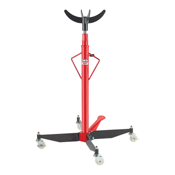
- Page 1 TRANSMISSION JACK MODEL NO: CTJ30 PART NO: 7612605 OPERATION AND MAINTENANCE INSTRUCTIONS GC0115...
-
Page 2: Specification
INTRODUCTION Thank you for purchasing this CLARKE Transmission Jack, designed for use in the removal and installation of transmissions and differentials. Before attempting to use this product, please read this manual thoroughly and follow the instructions carefully. In doing so you will ensure the safety of yourself and that of others around you, and you can look forward to your purchase giving you long and satisfactory service. -
Page 3: Safety Precautions
2. Do not allow personnel to operate the jack unless they have read these safety precautions. 3. Ensure that the jack is in good working order. Have any damaged parts repaired or replaced immediately. Use genuine Clarke parts only. The use of unauthorised parts may be dangerous and will invalidate the guarantee. -
Page 4: Safety Symbols
20. Use appropriate safety equipment, such as protective footwear, when using this jack. 21. When replacing parts, use only those supplied by Clarke International. Refer to the parts list on page10. 22. Ensure that the jack is properly maintained, and lubricated at all times, and that no rust or other forms of corrosion is allowed to weaken any part of it. -
Page 5: Unpacking And Assembly
1 x Fixings Kit Visually inspect all components to ensure that no damage was suffered in transit. Any damage should be reported to your CLARKE dealer immediately. 1. Fit the foot pedal to the base unit using the pivot pin and securing with the circlips at each end. - Page 6 4. Lay the column on its side, and bolt on the two wheel bracket assemblies, with the castors facing downwards ensuring the bracket sits over the locating peg. Use the two bolts and washers. Loosely tighten the bolts, but DO NOT fully tighten at this stage.
-
Page 7: Raising The Column
OPERATING INSTRUCTIONS WARNING: BEFORE LIFTING, ENSURE THE SAFETY PRECAUTIONS ARE STRICTLY FOLLOWED. NO RESPONSIBILITY CAN BE ACCEPTED FOR INCORRECT USE OF THE JACK 1. Ensure the vehicle is in a safe state as mentioned in the safety precautions, ensuring the ground on which the jack is to operate is level and solid. 2. -
Page 8: Maintenance
2. A slight dampness on the ram is normal, but where leakage is apparent, the ram seals must be renewed by your Clarke dealer. 3. The jack should be fully inspected annually as follows: • Check for cracks and deformation of components. -
Page 9: Parts List And Diagram
PARTS LIST & DIAGRAM Description No Description Bolt M8 x 40 Base for Steel Ball Release Handle Steel Ball Nut M8 Spring Base for Handle Bolt M12 x 25 Nut M10 Connecting Rod Parts & Service: 020 8988 7400 / E-mail: Parts@clarkeinternational.com or Service@clarkeinternational.com... - Page 10 Description No Description Screw M6 x 6 Permanent Seat for Spring Valve Rod Spring O-Ring Spring Sleeve Steel Ball Dust Ring Release Valve Base O Ring Washer Cover Base Screw M6 x 5 PTFE Washer Steel Ball O-Ring O-Ring PTFE Washer Washer Small Piston Reservoir...
-
Page 11: Declaration Of Conformity
DECLARATION OF CONFORMITY Parts & Service: 020 8988 7400 / E-mail: Parts@clarkeinternational.com or Service@clarkeinternational.com...
Need help?
Do you have a question about the CTJ30 and is the answer not in the manual?
Questions and answers