Table of Contents
Advertisement
Available languages
Available languages
Quick Links
Advertisement
Chapters
Table of Contents

Related Manuals for HomeMatic HM-Sec-SFA-SM


Summary of Contents for HomeMatic HM-Sec-SFA-SM
- Page 1 Installations- und Bedienungsanleitung (S. 2) Installation and operating manual (p. 20) Funk-Sirenen- und Blitzansteuerung Aufputzmontage: Radio-controlled alarm siren and flash actuator surface-mount: HM-Sec-SFA-SM...
- Page 2 2. Ausgabe Deutsch, Dezember 2009 Dokumentation © 2008 eQ-3 Ltd., Hong Kong Alle Rechte vorbehalten. Ohne schriftliche Zustimmung des Heraus- gebers darf dieses Handbuch auch nicht auszugsweise in irgendeiner Form reproduziert werden oder unter Verwendung elektronischer, mechanischer oder chemischer Verfahren vervielfältigt oder verarbei- tet werden.
-
Page 3: Table Of Contents
3.1.2 Anschlüsse, Sicherungen, Sonstiges ....7 Allgemeine Systeminformation zu HomeMatic ....8 Allgemeine Hinweise zum Funkbetrieb. -
Page 4: Hinweise Zu Dieser Anleitung
1 Hinweise zu dieser Anleitung Lesen Sie diese Anleitung sorgfältig, bevor Sie ihre HomeMatic-Kom- ponenten in Betrieb nehmen. Bewahren Sie die Anleitung zum späteren Nachschlagen auf! Wenn Sie das Gerät anderen Personen zur Nutzung überlassen, über- geben Sie auch diese Bedienungsanleitung. -
Page 5: Funktion
3 Funktion Die Sirenen-Blitz-Ansteuerung ist ein Aktor des HomeMatic-Systems. Sie ermöglicht die Ansteuerung von Signalgeräten der Alarmtechnik, typischerweise kombinierte, elektronische Sirenen und Blitzleuchten, über Funk-Sendebefehle. Diese Funk-Sendebefehle können von Fernbedienungen, Sensoren oder der HomeMatic-Zentrale CCU ausgesandt werden. Die Ausstattung und die Funktionen*: •... -
Page 6: Bedien- Und Anzeigeelemente, Anschlüsse
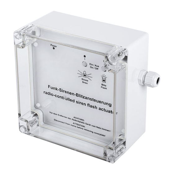
3.1 Bedien- und Anzeigeelemente, Anschlüsse 3.1.1 Frontplatte, Kabeldurchführungen (A) – Kabeldurchführung Signalgeräte-Anschluss (B) – Geräte-LED: Status der Spannungsversorgung (C) – Kanaltaste Sirenenfunktion (D) – Geräte-LED Sirenenfunktion (E) – Geräte-LED Blitzfunktion (F) – Kanaltaste Blitzfunktion (G) – Kabeldurchführung Netzkabel... -
Page 7: Anschlüsse, Sicherungen, Sonstiges
3.1.2 Anschlüsse, Sicherung, Sonstiges (H) – Sicherung für Sirenen-/Blitzausgang (I) – Anschlussklemmen für Sirene, Blitzlicht, Sabotagemeldung: KL 1: Eingang für Sabotagekontakt des Signalgebers KL 2: 12-V-Ausgang für Sirenenanschluss KL 3: 12-V-Ausgang für Blitzleuchtenanschluss (J) – Sabotagekontakt (K) – Netzanschluss KL 4 (L) –... -
Page 8: Allgemeine Systeminformation Zu Homematic
4 Allgemeine Systeminformation zu HomeMatic Dieses Gerät ist Teil des HomeMatic-Haussteuersystems und arbeitet mit dem bidirektionalen BidCoS Funkprotokoll. ® Alle Geräte werden mit einer Standardkonfiguration ausgeliefert. Darüber hinaus ist die Funktion des Gerätes über ein Programmier- gerät und Software konfigurierbar. Welcher weitergehende Funkti-... -
Page 9: Montage Und Installation
Objektes, gut erreichbar für den Eigentümer, nicht erreichbar für Unbefugte. Der Montageort ist so zu wählen, dass sich ein möglichst kurzer Leitungsweg zum Signalgerät ergibt und sich das Gerät sicher inner- halb der Funkreichweite des auslösenden HomeMatic-Gerätes, z. B. Zentrale oder Sensor, befindet. • Die Montagelage des Gerätes ist wie auf Seite 6/7 gezeigt einzu- halten, die Aussparung für den Akku muss nach unten zeigen. -
Page 10: Installation
Setzen Sie den Akku in die dafür vorgebene Aussparung ein , die Anschlussklemmen nach rechts, und schließen Sie ihn polrichtig an die Akku-Anschlussleitungen des Gerätes an (Rot an Plus, Schwarz an Minus). Achten Sie darauf, dass die Akku-Anschlussleitungen keine Elektronikteile auf der Platine berühren. Insbesondere dürfen die Leitungen nicht den Sabotagetaster blockieren. - Page 11 Sabotage* – – Sirene – – Blitz (Flash) Signalgerät – – * Signalgerät ohne Sabotagekontakt: KL4: L Netzanschluss Außenleiter KL4: N Netzanschluss Neutralleiter KL4: PE Netzanschluss PE KL1: + Sabotagekontakt Signalgerät, Plusanschluss KL1: – Sabotagekontakt Signalgerät, Minusanschluss KL2: + Sirenenansteuerung, +12 V, max. 500 mA KL2: –...
-
Page 12: Inbetriebnahme
7 Inbetriebnahme 7.1 Einfache Bedienfunktionen am Gerät Für das direkte Schalten der Sirene bzw. des Blitzlichts verfügt das Gerät über jeweils einen Bedientaster und eine Geräte-LED. Sie können die Funktionen des angeschlossenen Signalgerätes sowie die korrekte elektrische Installation sofort nach der Installation, ohne Anlernen, überprüfen. -
Page 13: Bedienung
Sabotagekontakt Aktor, Trennung vom Stromnetz) wird eine Sabotagemeldung an die Zentrale gesendet. Die Auswertung der Sabotagemeldungen kann nur über eine Zentrale, wie die HomeMatic-Zentrale CCU oder die Funk- Alarmzentrale erfolgen. Sollten für diese Ereignisse Alarmszenarien angelegt sein, so sollten diese vor einem Serviceeingriff (z. B. Akkuwechsel) deaktiviert werden. -
Page 14: Verhalten Nach Spannungswiederkehr
In diesem Falle ist die Verschlüsselung mit einem vom Auslieferungs- schlüssel verschiedenen System-Sicherheitsschlüssel aktiv. Um den Aktor zurückzusetzen, müssen sie die Konfigurationssoft- ware der Zentrale zum Zurücksetzen benutzen! Der Vorgang ist in der Anleitung zur Zentralen-Software beschrieben. 10 Verhalten nach Spannungswiederkehr Die folgenden Hinweise beschreiben das Verhalten des Gerätes nach Netzausfall (bzw. -
Page 15: Anzeige Des Betriebszustandes
11.2 Anzeige des Betriebszustandes Sobald ein Schaltausgang aktiv ist, leuchtet die entsprechende Ka- nal-LED dauerhaft, bei aktivem Ausschalttimer blinkt die LED. Nach Konfiguration des Aktors über die Zentrale oder über ein Pro- grammiertool zeigt die LED neben den beschriebenen noch zusätz- liche Zustände des Geräts an. -
Page 16: Wartung Und Reinigung
• Das Gerät verfügt über eine interne Überwachung der Akkuqua- lität durch Messung des Innenwiderstands. Ist der Innenwider- stand zu hoch, wird der Akku als defekt gemeldet. Durch die Alterung des Akkus und die damit abnehmende Leistungsfähigkeit werden darüber hinaus die Wechselintervalle in Abhängigkeit von der Betriebstemperatur aus nachstehender Tabelle empfohlen: Betriebstemperatur Akku-Wechselintervall... -
Page 17: Sicherungswechsel
wenden Sie keine lösungsmittelhaltigen Reinigungsmittel, das Kunst- stoffgehäuse und die Beschriftung können dadurch angegriffen werden. 13.2 Sicherungswechsel Bei Verpolung des Bleiakkus oder einem Kurzschluss bzw. Überlast an den Schaltausgängen löst die interne Sicherung aus, die sich neben der Anschlussklemme KL3 unter einer Schutzhaube befindet. Vor Ausbau der Gerätefrontplatte Netzspannung freischalten! •... -
Page 18: Technische Daten
dass die Anschlusskabel nicht beschädigt werden und keinen Kontakt zu den Bauteilen auf den Platinen im Gerät haben. Montieren Sie Frontplatte und Abdeckung und schalten Sie die Netzspannung wieder zu. Testen Sie die Gerätefunktion. Vorsicht! Explosionsgefahr bei unsachgemäßem Austausch der Batterie. - Page 19 Das CE-Zeichen ist ein Freiverkehrszeichen, das sich aus- schließlich an die Behörden wendet und keine Zusicherung von Eigenschaften beinhaltet. Entsorgungshinweis Gerät nicht im Hausmüll entsorgen! Elektronische Geräte sind entsprechend der Richtlinie über Elektro- und Elektro- nik-Altgeräte über die örtlichen Sammelstellen für Elektronik-Altgeräte zu entsorgen.
- Page 20 2nd English edition, December 2009 Documentation © 2008 eQ-3 Ltd., Hong Kong All rights reserved. This manual may not be reproduced in any format, either in whole or in part, nor may it be duplicated or edited by electronic, mechanical or chemical means, without the written consent of the publisher.
- Page 21 3.1.2 Connections, fuses, miscellaneous..... 25 General system information about HomeMatic ... . 26 General information about radio control.
-
Page 22: Information About These Instructions
1 Information about these instructions Read this manual carefully before starting to use your HomeMatic components. Keep the instructions handy so you can refer to them at a later date. If you hand over the device to other persons for use, please hand over the operating manual as well. -
Page 23: Function
Internal battery status monitoring with signalling of error states, deep discharge protection and protection against polarity reversal. * Some functions are only available in conjunction with the HomeMatic central control unit; refer to the manual for further information. Please ensure that you download the latest HomeMatic... -
Page 24: Controls And Indicators, Connections
3.1 Controls and indicators, connections 3.1.1 Front panel, cable bushings (A) – Cable bushing for signalling device connection (B) – Device LED: status of the power supply (C) – Channel button for siren function (D) – Device LED for siren function (E) –... -
Page 25: Connections, Fuses, Miscellaneous
3.1.2 Connections, fuse, miscellaneous (H) – Fuse for siren/flashing output (I) – Terminals for siren, flashing light, tamper signal: KL 1: Input for signalling device’s tamper contact KL 2: 12 V output for siren connection KL 3: 12 V output for flashing light connection (J) – Tamper contact (K) –... -
Page 26: General System Information About Homematic
4 General system information about HomeMatic This device is part of the HomeMatic home control system and works with the bi-directional BidCoS wireless protocol. ® All devices are delivered in a standard configuration. The functionality of the device can also be configured with a program- ming device and software. -
Page 27: Mounting And Installation
The mounting location should be selected so that the line to the signalling device is as short as possible and the device is located within the wireless range of the triggering HomeMatic device, e.g. the central control unit or a sensor. -
Page 28: Installation
• Once the device has been fastened in place the battery should be fitted and connected. Insert the battery into the designated recess with the terminals to the right and connect the poles to the appropriate battery connecting cables on the device (red to +, black to -). Make sure that the battery connecting cables do not make contact with any of the electronic components on the PCB. - Page 29 Tamper* Sabotage* – – Siren Sirene – – Flash Blitz (Flash) Signalling device Signalgerät – – *Signalling device without tamper contact: * Signalgerät ohne Sabotagekontakt: KL4: L Mains connection L-conductor KL4: N Mains connection neutral conductor KL4: PE Mains connection PE KL1: + Tamper contact signalling device, positive connection...
-
Page 30: Start-Up
7 Start-up 7.1 Simple operator functions on the device The siren and the flashing light can be operated directly using the control buttons and LEDs on the device (there is one control button and one LED for each). You can check the functions of the connected signalling device, as well as the integrity of the electrical installation, immediately after installation (without teaching-in). -
Page 31: Operation
8 Operation After teach-in has been performed, simple operator and activation functions are available via the taught-in control elements, sensors or the central control unit: • Each channel can be activated or deactivated in accordance with the taught-in operator or activation element. • If an attempt is made to tamper with the device (tamper contact on the signalling device, actuator tamper contact, disconnection from power supply), a tamper signal is sent to the central control unit. -
Page 32: Response To Power Recovery
In this case, coding is activated using a system security key that differs from the one supplied with the product. To reset the actuator, you will have to use the configuration software for resetting the central control unit. The procedure to follow is described in the manual for the central control unit software. -
Page 33: Operating Status Display
11.2 Operating status display As soon as a switching output is active, the corresponding channel LED will light up continuously; if the switch-off timer is active, the LED will flash. Once the actuator has been configured using the central control unit or a programming tool, the LED will indicate other device states in addition to those already described. -
Page 34: Maintenance And Cleaning
indicated as faulty. If this status is displayed even after the designated charging time, replace the battery. • The device has an internal feature for monitoring battery quality by means of measuring internal resistance. If the internal resistance is too high, a battery fault will be displayed. As the battery ages and its performance deteriorates, we recommend the replacement intervals listed in the following table, which are dependent upon operating temperature: Operating temperature... -
Page 35: Changing The Fuse
more stubborn marks. Do not use any detergents containing solvents, as they could corrode the plastic housing and label. 13.2 Changing the fuse Reversing the polarity of the lead battery or a short circuit/overload at the switching outputs will blow the internal fuse located next to terminal KL3 underneath a protective cover. -
Page 36: Technical Data
Fit the front panel and cover and reconnect the mains voltage. Test the function of the device. Caution! There is a risk of explosion if the battery is not replaced correctly. Used batteries should not be disposed of with regular domestic waste. Instead, they should be taken to your local battery disposal point. - Page 37 The CE sign is a free trade sign addressed exclusively to the authorities and does not warrant any properties. Instructions for disposal Do not dispose of the device with regular domestic waste. Electronic devices are to be disposed of in accordance with the Waste Electrical and Electronic Equipment Directive via the local collection point for waste electronic devices.
- Page 38 eQ-3 AG Maiburger Straße 29 D-26789 Leer www.eQ-3.com...
Need help?
Do you have a question about the HM-Sec-SFA-SM and is the answer not in the manual?
Questions and answers