Table of Contents
Advertisement
Available languages
Available languages
Quick Links
Advertisement
Chapters
Table of Contents

Related Manuals for HomeMatic HMW-LC-Sw2-DR


Summary of Contents for HomeMatic HMW-LC-Sw2-DR
- Page 1 Installations- und Bedienungsanleitung (S. 2) Installation and Operating Manual (p. 34) Schalt-/Dimmaktor, Rollladenaktor Drahtbus Hutschienenmontage: Switch/dimming actuator, shutter actuator Wired bus for mounting on DIN rails: HMW-LC-Sw2-DR HMW-LC-Bl1-DR HMW-LC-Dim1L-DR...
-
Page 2: Table Of Contents
Funktion ......8 Dokumentation © 2007 eQ-3 AG, Deutschland Allgemeine Systeminformation zu HomeMatic 12 Alle Rechte vorbehalten. Ohne schriftliche Zustim- Allgemeine Hinweise zum Bussystem . -
Page 3: Hinweise Zu Dieser Anleitung
Elektro-Fachkraft (nach VDE 0100) erfolgen. Lesen Sie diese Anleitung sorgfältig, bevor Sie Ihre Dabei sind die geltenden Unfallverhütungsvor- HomeMatic Komponenten in Betrieb nehmen. Bewah- schriften zu beachten. ren Sie die Anleitung zum späteren Nachschlagen auf! Wenn Sie das Gerät anderen Personen zur Nutzung Zur Vermeidung eines elektrischen Schlages überlassen, übergeben Sie auch diese Bedienungs-... - Page 4 Öffnen Sie die Geräte nicht, sie enthalten keine Verwenden Sie nur Jalousien bzw. Rollladen mit End- durch den Anwender zu wartenden Teile. Das lagenschalter (mechanisch oder elektronisch)! Prüfen Öffnen der Geräte birgt die Gefahr eines Sie die Endlagenschalter der angeschlossenen Mo- Stromschlages.
-
Page 5: Funktion
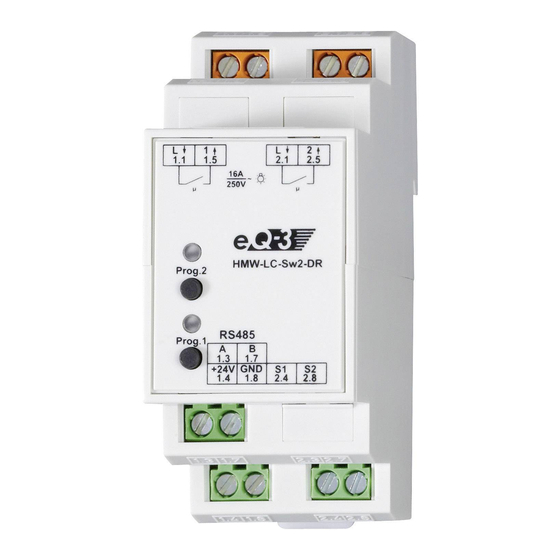
An einem Tastereingang sind beliebig viele potentialfreie Taster parallel anschließbar. • Nichtflüchtiger Speicher für Konfigurationsdaten. • Galvanisch getrennter Leistungs- und Busteil. HMW-LC-Sw2-DR • Zwei getrennt konfigurierbare Schaltkanäle. • Belastung pro Kanal im 230 V-Stromnetz von bis zu 16 A. (A) Klemme Schaltausgang 1... - Page 6 HMW-LC-Bl1-DR HMW-LC-Dim1L-DR • Belastung pro Kanal im 230 V-Stromnetz von bis • Phasenanschnitt-Technik für ohmsche und zu 4 A Motorlast. induktive Lasten. • Belastbar bis zu 200 VA. (A) Klemme Anschluss Außenleiter (B) Klemmen Schaltausgang „Öffnen“ und „Schließen“ (A) Klemmen L/N (C) Bus A (B) Klemmen N/gedimmte Phase (D) Bus B...
-
Page 7: Allgemeine Systeminformation Zu Homematic
Lastseite zu HomeMatic Da lastseitig typischerweise 230 V-Netzverbraucher geschaltet werden, ist hier der Einsatz von VDE- Dieses Gerät ist Teil des HomeMatic Haussteuersy- gerechten Installationsleitungen, wie beispielsweise stems. Alle Geräte werden mit einer Standardkonfi- NYM-Leitung etc., erforderlich. Die Leitungsquer- guration ausgeliefert. Darüber hinaus ist die Funktion schnitte richten sich nach den gängigen VDE-Vor-... -
Page 8: Topologie Des Bussystems
Trennung der einzelnen 5.2 Topologie des Bussystems Busabschnitte zu erreichen und ggf. eine Fehlersuche zu vereinfachen. Üblicherweise ist dies der Raum, in Aus Gründen der Übersicht sollten die HomeMatic dem die Zentrale des HomeMatic-Systems installiert Wired-Komponenten immer gruppenweise in Unterver- wird. - Page 9 Vergewissern Sie sich, dass alle Anschlüsse 0,14 – 2,50 0,14 – 1,5 fest und sicher in den Installationsklemmen fi- xiert sind. HMW-LC-Sw2-DR • Verdrahten Sie die Hutschienenmodule zur Busspannungsversorgung (Klemmen 1.4 und 1.8) mit dem Netzteil. Achten Sie dabei strikt auf den polaritätsrichtigen Anschluss an den Klemmen.
- Page 10 Klemme Funktion HMW-LC-Bl1-DR Außenleiteranschluss Kanal 1 Geschaltete Phase Kanal 1 Außenleiteranschluss Kanal 2 Geschaltete Phase Kanal 2 RS485-Bus (Bus A) RS485-Bus (Bus B) Spannungsversorgung 24 V / DC Spannungsversorgung Massean- schluss Tastereingang S1 Tastereingang S2 Die Schaltkanäle besitzen potentialfreie Relaiskon- takte.
- Page 11 Klemme Funktion HMW-LC-Dim1L-DR Außenleiteranschluss Außenleiteranschluss Geschaltete Phase „Öffnen“ Geschaltete Phase „Schließen“ RS485-Bus (Bus A) RS485-Bus (Bus B) Spannungsversorgung 24 V / DC Spannungsversorgung Massean- schluss Tastereingang S1 Tastereingang S2...
-
Page 12: Anlernen
Sie mit dem Anlernen beginnen! Anlernmodus. • Betätigen Sie nun einen Taster an dem Damit das Gerät in Ihr HomeMatic System integriert Tastereingang (am selben oder einem beliebigen wird und mit anderen HomeMatic Komponenten kom- anderen am Bus angeschlossenen Moduls), dem munizieren kann, muss es zunächst angelernt werden. - Page 13 Geräten verknüpfen oder diesen Vorgang. • in Zentralenprogrammen nutzen zu können, muss es zunächst an die HomeMatic Zentrale ange- Je nach Aktor werden Tastereingänge unterschiedlich lernt werden. Das Anlernen neuer Geräte an die Zen- angelernt: trale erfolgt über die HomeMatic Bedienoberfläche „WebUI“.
-
Page 14: Bedienung
6.1.3 Neu angelernte Geräte konfigurieren Nachdem Sie Ihren Aktor an die HomeMatic Zentrale angelernt haben, wird er in den „Posteingang“ ver- schoben. Hier muss Ihr Gerät und die dazugehörigen Kanäle zunächst konfiguriert werden, damit es für Be- dien- und Konfigurationsaufgaben zur Verfügung steht. Vergeben Sie einen Namen und ordnen Sie das Gerät einem Raum zu. -
Page 15: Bedienung Über Angelernte Taster
Aktor Verhalten der Programmier- Rollladen- Je nachdem ob der Anlernmo- tasten aktor dus am Aktor mit der ▲- oder ▼- Taste ausgelöst wurde, wird Schaltaktor, Kanal-Tasten verhalten sich wie die anzulernende Taste als „Öff- Dimmaktor Toggle-Taster: AN/AUS nen“ oder „Schließen“ angelernt, Rollladenaktor Die Kanaltasten verhalten sich nicht als Toggle-Taste. -
Page 16: Wartung Und Reinigung
Das Gerät enthält eine interne Gerätesicherung zum (L x B x H) Schutz des Triacs vor zu großer Strombelastung. Sollte das Gerät überlastet werden und die Sicherung HMW-LC-Sw2-DR auslösen, kann sie von einem Fachmann ersetzt wer- Ausgänge: 2 unabhängige potential- den! freie Relaisschaltausgän-... - Page 17 HMW-LC-Bl1-DR Entsorgungshinweis Ausgänge: 2 abhängig schaltende Gerät nicht im Hausmüll entsorgen! Elektro- potentialfreie Relaisschalt- nische Geräte sind entsprechend ausgänge der Richtlinie über Elektro- und Elektronik-Alt- Schaltvermögen: 230 V / 50 Hz / 4 A Motor- geräte über die örtlichen Sammelstellen last für Elektronik-Altgeräte zu entsorgen.
- Page 18 Function ......39 General system information on HomeMatic . . 43 1. English edition 10/2008 General information on the bus system .
-
Page 19: Information Concerning These Instructions
0100). Always observe the applicable accident prevention regulations. Read these instructions carefully before beginning operation with your HomeMatic components. Keep the Disconnect the power to devices before wor- instructions handy for later consultation! Please hand- king on them to prevent electrocution (switch over the operating manual as well when you hand-over circuit breaker). -
Page 20: Function
Make sure that the specified wiring and wire cross- The dimmer is only suitable for light bulbs and for low sections are used when connecting to device ter- voltage NV halogen lamps with conventional transfor- minals. mers! Switch actuator: The devices are not intended to be isolated. The load Follow all technical specifications, especially the ma- is not electrically isolated from the mains. - Page 21 HMW-LC-Sw2-DR HMW-LC-Bl1-DR • Two separately configurable switch channels. • Load per channel in 230 V power supply of up to 4 • Load per channel in 230 V power supply of up to 16 A. A motor load. Terminal switch output 1...
-
Page 22: General System Information On Homematic
Phase cutting technology for resistive and inductive loads. • Capable of loads up to 200 VA. This device is a component of the HomeMatic Home Control System. All devices are delivered in a standard configuration. The functionality of the device can also be configured with a programming device and software. -
Page 23: Topology Of The Bus System
5.2 Topology of the bus system nominal load range of actuators. The HomeMatic Wired components should always be Control side mounted in groups of sub-divisions to provide a better On the control side however, only non-hazardous safe- overview. -
Page 24: Installation
• Wire the DIN rail modules for the bus power supply Normally, this is the room in which the HomeMatic sys- (terminals 1.4 and 1.8) with the power supply. tem Central Control Unit is installed. Make sure that the connections are made with correct polarity on the terminals. - Page 25 HMW-LC-Sw2-DR Terminal Function External conductor connection Chan- nel 1 Switched channel 1 External conductor connection Chan- nel 2 Switched channel 2 RS485-Bus (Bus A) RS485-Bus (Bus B) Power supply 24 V / DC Power supply Ground connection Button input S1...
- Page 26 HMW-LC-Bl1-DR Terminal Function External conductor connection External conductor connection Switched channel "Open" Switched channel "Close" RS485-Bus (Bus A) RS485-Bus (Bus B) Power supply 24 V / DC Power supply Ground connection Button input S1 Button input S2...
- Page 27 MW-LC-Dim1L-DR Terminal Function External conductor connection Neutral conductor Neutral conductor Dimmed channel RS485-Bus (Bus A) RS485-Bus (Bus B) Power supply 24 V / DC Power supply Ground connection Button input S1 Button input S2...
-
Page 28: Teaching-In
LED goes dark on the devices, you must teach it in first. You can teach-in the actuator. device directly to other HomeMatic devices or to the • Test the assignment by pressing the respective HomeMatic Central Control Unit: button. - Page 29 HomeMatic software „WebUI“. Therefore, your appear in the inbox of your software interface. The shutter contact has to be taught-in to the HomeMatic button „Inbox (x new devices)“ indicates how many Central Control Unit first. New devices are taught-in to new devices have been taught-in successfully.
-
Page 30: Operation
Please After teaching, simple operating functions are available refer to the HomeMatic WebUI manual for more details using the taught control elements. (available for download in the „Downloads“ area of the website www.homematic.com). -
Page 31: Resetting To Factory Status
Standard DIN rail housing with 2 TE wide 87 x 35 x 64 mm Maintenance and cleaning (L x W x H) This product is maintenance-free. HMW-LC-Sw2-DR Repairs are only to be done by trained profes- Outputs: 2 independent sionals. potential-free... - Page 32 Control inputs: 2 independent button in- Instructions for disposal puts (safety extra-low volt- Do not dispose off the device as part of age) household garbage! Electronic devices are to be disposed of in ac- cordance with the guidelines concerning elec- HMW-LC-Bl1-DR trical and electronic devices via the local collec- Outputs:...
- Page 33 Bevollmächtigter des Herstellers: Manufacturer’s authorised representative: eQ-3 AG Maiburger Straße 29 26789 Leer / GERMANY www.eQ-3.de...
Need help?
Do you have a question about the HMW-LC-Sw2-DR and is the answer not in the manual?
Questions and answers