
Related Manuals for GE DigitalFlow GC868


Summary of Contents for GE DigitalFlow GC868
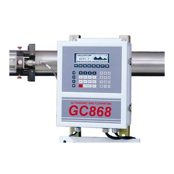
- Page 1 Sensing & Inspection Technologies DigitalFlow™ GC868 Panametrics Gas Clamp-On Ultrasonic Flowmeter Service Manual (1 and 2-Channel)
- Page 2 Sensing & Inspection Technologies DigitalFlow™ GC868 Panametrics Gas Clamp-On Ultrasonic Flowmeter Service Manual (1 and 2-Channel) 910-226SF1 April 2008 The DigitalFlow GC868 is a GE Panametrics product. GE Panametrics has joined other GE high-technology businesses under a new name—GE Sensing & Inspection Technologies.
- Page 3 2. If GE instructs you to send your instrument to a service center, it must be shipped prepaid to the authorized repair station indicated in the shipping instructions.
-
Page 4: Table Of Contents
April 2008 Table of Contents Chapter 1: Calibration Introduction ................1-1 Menu Map . - Page 5 April 2008 Table of Contents (cont.) Chapter 3: Diagnostics Introduction ................3-1 Displaying Diagnostic Parameters .
- Page 6 Chapter 1...
- Page 7 Calibration Introduction........... . 1-1 Menu Map .
-
Page 8: Introduction
April 2008 Introduction Calibrating the Model GC868’s analog outputs and inputs is explained in this chapter. In addition, testing the optional totalizer/ frequency and alarm relay outputs is discussed. The following specific topics are included: • calibrating the built-in Slot 0 analog outputs •... -
Page 9: Calibrating The Analog Outputs
April 2008 Calibrating the Analog Every Model GC868 flowmeter includes two built-in analog outputs Outputs Slot 0 (A and B) at terminal block , which is designated as Additional analog outputs may be added to the Model GC868 by installing an Analog Outputs Option Card in one (or more) of the six expansion slots. -
Page 10: Accessing The Calibration Menu
April 2008 Calibrating the Analog Outputs (cont.) Terminal Block (Option Card) Ammeter Figure 1-2: Ammeter Connection for Slots 1-6 (Output A) Accessing the Calibration [CAL] 1. Press the key to enter the Calibration Program. Menu [Fx] 2. Press to calibrate the desired slot. (The option bar will include a slot listing for each installed option card.) [Fx] 3. -
Page 11: Calibrating The High End Of The Output Range
April 2008 Calibrating the High End [F2] 1. Press to calibrate the high end of the output range. of the Output Range [F1] [F2] DOWN 2. Press to adjust the ammeter reading , until [F3], Numer, a 20 mA reading is achieved. If you press enter a [ENT]. - Page 12 April 2008 Calibrating the Analog Table 1-1: Expected Ammeter Readings Outputs (cont.) % Full Scale 4-20 mA Scale* 0-20 mA Scale* 4.000 0.000 5.600 2.000 7.200 4.000 8.800 6.000 10.400 8.000 12.000 10.000 13.600 12.000 15.200 14.000 16.800 16.000 18.400 18.000 20.000 20.000...
-
Page 13: Calibrating The Analog Inputs
April 2008 Calibrating the Analog Analog inputs may be added to the Model GC868 flowmeter by Inputs installing an Analog Inputs Option Card in one (or more) of the six expansion slots. The option card contains two analog inputs, which are designated as A and B. -
Page 14: Accessing The Calibration Menu
April 2008 Calibrating the Analog For this discussion, assume that the option card has been installed in Inputs (cont.) Slot x Note: The zero point of the analog input may be set for either 0 mA or 4 mA. However, the calibration procedure always uses the 4 mA point, as the meter will extrapolate from this value to obtain the 0 mA point. -
Page 15: Alow Option = [F1]
April 2008 aLOW Option = [F1] [ENT] 1. Enter the low reference value and press the key. [F1] [F2] 2. Press to store the current low reference value or press ANALOG INPUT cancel the entry. In either case, the prompt will reappear. -
Page 16: Calibrating The Rtd Inputs
April 2008 Calibrating the RTD Calibrating an RTD option card involves a different procedure than Inputs for other analog input cards. However, you access the card in the same manner as other cards. Accessing the Calibration [CAL] 1. Press the key to enter the Calibration Program. -
Page 17: Numer Option = [F2]
April 2008 Numer Option = [F2] The Numer option allows the user to calculate the temperature vs. resistance information. To do this, the user must first collect data using the RTDs option in the PRINT menu (discussed in Chapter 5 of the Programming Manual). -
Page 18: Testing The Alarm Relays
April 2008 Testing the Alarm Relays Alarm relays may be added to the Model GC868 by installing an Alarms Option Card in one (or more) of the six expansion slots. Each option card includes three alarm relays, which are designated as A, B, and C. - Page 19 April 2008 Testing the Alarm Relays Note: The procedure for testing Alarm Relay A is identical to that for (cont.) Alarm Relays B and C testing . However, make sure that the ohmmeter is connected to the desired normally-open or normally-closed contact of the currently selected relay.
-
Page 20: Testing The Totalizer/Frequency Outputs
April 2008 Testing the Totalizer/ Totalizer/frequency outputs may be added to the Model GC868 by Frequency Outputs installing a Totalizer/Frequency Option Card in one (or more) of the six expansion slots. Each option card includes four outputs, which are designated as A, B, C and D. To test the outputs, connect a frequency counter to the card’s terminal block as shown in Figure 1-5 below. -
Page 21: Entering Pulse Number
April 2008 Entering Pulse Number 5. Enter the number of pulses desired (between 1 and 10,000) and [ENT] press the key. That number of pulses will then be output at the specified frequency. 6. Repeat Steps 3, 4 and 5 to test all four of the frequency/totalizer outputs. - Page 22 April 2008 SLOT0 SLOT1 SLOT2 SLOT3 SLOT4 SLOT5 SLOT6 Slot x (Option Card) Slot 0 Outputs (TB I/O) Slot x Inputs (Analog Inputs) Slot x Outputs (Alarms) ANALOG OUTPUT ANALOG INPUT ALARMS 4 mA 20 mA TEST EXIT aLOW aHIGH 4 mA 20 mA EXIT...
- Page 23 Chapter 2...
- Page 24 Error Codes and Screen Messages Introduction........... . 2-1 E0: No Error .
-
Page 25: Chapter 2: Error Codes And Screen Messages
April 2008 Introduction The Model GC868 ultrasonic flowmeter is a reliable, easy to maintain instrument. When properly installed and operated, as described in the Startup Guide, the meter provides accurate flow rate measurements with minimal user intervention. However, if a problem should arise with the electronics console, the transducers or the flowcell, a built-in error code message system greatly simplifies the troubleshooting process. -
Page 26: E0: No Error
April 2008 E0: No Error Problem: No error condition currently exists. Cause: This message appears briefly to confirm that the cause for a previous error condition has disappeared, has cleared or been resolved. Action: No action is required. E1: Low Signal Problem: Poor ultrasonic signal strength or the signal exceeds the limits entered via the User Program. -
Page 27: E4: Signal Quality
April 2008 E4: Signal Quality Problem: The signal quality is outside the limits programmed in the SETUP submenu of the User Program. Cause: Too high a signal strength may be caused by the failure of an electronic component. Too low a signal strength may be caused by a flowcell or electrical problem. -
Page 28: E9: Press In
April 2008 E9: Press In Problem: This message indicates a pressure input error. Cause: The pressure exceeds the specified limits for the analog inputs option card. Action: Check the pressure transmitter and the connecting cable. Refer to Chapter 1, Calibration, and recalibrate the analog inputs on the option card. -
Page 29: E16: High Signal
April 2008 E16: High Signal Problem: The meter signal strength exceeds the limits entered via the User Program. Cause: A signal that exceeds the programmed limits is probably caused by the entry of an improper value in the TRANSDUCER PIPE submenu of the User Program. - Page 30 April 2008 Table 2-1: Screen Messages (Continued) Message Meaning Duplicate name, The site file or log name is already in use. Enter a different name. Enter another. End Time must exceed This message appears when in the LOG menu. Enter an end time that is Start Time by 5 min.
- Page 31 Chapter 3...
- Page 32 Diagnostics Introduction........... . 3-1 Displaying Diagnostic Parameters.
-
Page 33: Introduction
April 2008 Introduction This chapter explains how to troubleshoot the Model GC868 if problems arise with the electronics console, the flowcell, or the transducers. Indications of a possible problem include: • display of an error message on the active display screen •... - Page 34 April 2008 Displaying Diagnostic Table 3-1 below lists the available diagnostic parameters for the Parameters (cont.) Model GC868. The first column in the table shows the parameter as it appears on the option bar, while the second column shows the parameter as it appears in the prompt area after it has been selected.
- Page 35 April 2008 Table 3-1: Available Diagnostic Parameters (Continued) Option Screen Display Description Good SuperC Displays supercompressibility as N.A. N.A. calculated by the NX19 equation or custom table. AcVOL Act Vol. KACF/MIN Displays actual volumetric flow. N.A. N.A. StVOL Std Vol. KSCF/MIN Displays standard volumetric flow, N.A.
-
Page 36: Diagnostic Record
April 2008 Diagnostic Record [EXIT] EXIT Upon leaving the Diagnostic Menu via the key or the option on the option bar, the display screen will continue to show the last diagnostic parameter that was selected. To return to normal measurement mode, select a channel to display (for a 2-Channel meter only) and then select the desired display parameter. -
Page 37: Pipe Problems
The accuracy of the flow rate measurements is no better than the accuracy of the programmed pipe dimensions. For a flowcell supplied by GE, the correct data will be included in the documentation. For other flowcells, measure the pipe wall thickness and diameter with the same accuracy desired in the flow rate readings. -
Page 38: Transducer Problems
April 2008 Transducer Problems Ultrasonic transducers are rugged, reliable devices. However, they are subject to physical damage from mishandling and chemical corrosion. The most common transducer problems are listed below: 1. LEAKS: Leaks may occur around the transducer. Repair such leaks immediately. - Page 39 Chapter 4...
- Page 40 Parts Replacement Introduction........... . 4-1 Fuse Replacement .
-
Page 41: Chapter 4: Parts Replacement
April 2008 Introduction The electronics console of the Model GC868 has been designed to permit easy on-site upgrades and parts replacement. See Figure 4-1 on page 4-10 and Figure 4-2 on page 4-11 for details of the standard GC868 electronics console assembly. The instructions in this chapter, along with a few common tools, are all that is required to perform the following tasks: •... -
Page 42: Fuse Replacement
April 2008 Fuse Replacement If it has been determined that the fuse in the Model GC868 requires replacement, complete the following steps: 1. Remove the main power to the electronics console. !WARNING! The main power to the Model GC868 must be disconnected before proceeding. -
Page 43: Removing The Printed Circuit Board
April 2008 Removing the Printed All of the remaining maintenance procedures discussed in this Circuit Board chapter require removal of the printed circuit board. To accomplish this task, see Figure 4-1 on page 4-10 and Figure 4-2 on page 4-11 and complete the following: 1. -
Page 44: Replacing The Eprom
April 2008 Removing the Printed 8. Tilt the top of the printed circuit board forward, and mark the top Circuit Board (cont.) edges of the two ribbon-cable connectors. Then, remove these cables from their connectors on the rear of the board. 9. -
Page 45: Installing An Option Card
April 2008 Installing an Option Card The Model GC868 flowmeter can accommodate up to six option cards. The option cards are installed into sockets on the bottom of the printed circuit board, and they are held in place with a metal bracket. A single metal bracket is used to secure all the installed option cards. -
Page 46: Replacing The Lcd Display
April 2008 Replacing the LCD The Model GC868’s measurements are displayed on a a two-pane Display LCD graphic display panel. The LCD display normally provides years of dependable service, but it is easily field-replaceable when necessary. To replace the LCD display, see Figure 4-1 on page 4-10 for the component locations, and complete the following steps: 1. -
Page 47: Installing The Printed Circuit Board
April 2008 Installing the Printed Whether the printed circuit board was removed for replacement or for Circuit Board one of the other procedures discussed in this chapter, reinstallation of the printed circuit board is the final step in the process. Refer to Figure 4-1 on page 4-10 and complete the following steps: Caution! During this procedure, be very careful not to damage the... - Page 48 April 2008 Installing the Printed 5. Connect the twisted-pair backlight cable to socket on the left Circuit Board (cont.) edge of the printed circuit board. This plug is polarized so that it can only be installed in the proper orientation, with the black wire above the red wire.
-
Page 49: Spare Parts
April 2008 Note: Be sure to enter a complete and detailed account of the service procedure performed on the Model GC868 in Appendix A, Service Record. Spare Parts All of the necessary components to upgrade or repair the Model GC868 flowmeter are readily available from the factory. As a convenient reference, some of the more common spare parts are listed in Table 4-2 below. -
Page 50: Bottom View
April 2008 Front View Keypad Cable Mounting Screw Main Shroud Main Shroud 8 places Display Cable Nuts & Washers Nuts & Washers WARNING 4 places Display Shroud Option Card Socket GATE DRTN TWIND RWIND ALARMS ANALOG OUT ANALOG IN TOTL/FREQ RTD IN LCD Display Metal Bracket... - Page 51 April 2008 Keypad Cable Short Standoff Vertical Components 3 places Backlight Cable Long Standoff EPROM (U4) 3 places LCD Display Beveled BLACK Corner Keypad Connector (J50) Display Connector (J52) Display Cable – N/L2 J2 Connector Fasteners (typ.) Option Card Connectors Metal Bracket Rear View PC Board Ground Wire...
- Page 52 Appendix A...
-
Page 53: Appendix A: Service Record
Service Record Introduction........... . A-1 Data Entry . -
Page 54: Introduction
April 2008 Introduction Whenever any service procedure is performed on the Model GC868 flowmeter, the details of the service should be recorded in this appendix. An accurate service history of the meter can prove very helpful in troubleshooting any future problems. Data Entry Record complete and detailed service data for the Model GC868 in Table A-1 below. - Page 55 April 2008 Table A-1: Service Record (Continued) Date Description of Service Performed By Service Record...
-
Page 56: Diagnostic Parameters
April 2008 Diagnostic Parameters After a successful initial installation of the Model GC868 and whenever any system malfunction is noticed, the values for the diagnostic parameters should be entered in Table A-2 below. Table A-2: Diagnostic Parameters Parameter Initial Current Parameter Initial Current... - Page 57 Appendix B...
- Page 58 Optional Enclosures Introduction........... . B-1 Rack Mount Enclosure.
-
Page 59: Appendix B: Optional Enclosures
April 2008 Introduction The Model GC868 is available in optional enclosure types, each of which has been designed to permit easy on-site upgrades and parts replacement. See the foldout drawings at the end of this appendix for details of the applicable GC868 electronics console assembly. The instructions in this appendix, along with a few common tools, are all that is required to perform the following tasks: •... -
Page 60: Rack Mount Fuse Replacement
April 2008 Rack Mount Fuse If it has been determined that the fuse in the Model GC868 requires Replacement replacement, refer to Figure B-1 on page B-10 and Figure B-2 on page B-11, and complete the following steps: 1. On the rear panel of the meter, set the power switch to the OFF position and pull the power cord out of its receptacle. -
Page 61: Rack Mount Option Card Installation
April 2008 Rack Mount Option Card The Model GC868 flowmeter can accommodate up to six option Installation cards in a manner similar to that used in a PC. The option cards are installed into sockets on the printed circuit board, and they are held in place with a metal bracket. -
Page 62: Rack Mount Option Card Installation
April 2008 Rack Mount Option Card 6. Place the metal bracket over the option cards, making sure that all Installation (cont.) installed option cards are inserted into the plastic card guides in the bracket. The bracket must be oriented so that the six card guides are directly above the six sockets on the printed circuit board (do not install the bracket rotated 180°... -
Page 63: Rack Mount Eprom Replacement
April 2008 Rack Mount EPROM The Model GC868’s User Program is stored on an erasable Replacement programmable read only memory (EPROM) chip. The EPROM, which is designated as component , is located on the corner of the printed circuit board just behind the keypad on the front panel. EPROM replacement may be required to replace a defective chip or to upgrade to a newer software version. -
Page 64: Rack Mount Lcd Display Replacement
April 2008 Rack Mount LCD Display The Model GC868 measurements are displayed on a two-pane LCD Replacement graphic display panel. The LCD display normally provides years of dependable service, but it is field-replaceable when necessary. To replace the LCD display, refer to Figure B-2 on page B-11 and complete the following steps: 1. -
Page 65: Rack Mount Printed Circuit Board Replacement
April 2008 Rack Mount LCD Display 7. Fasten the display shroud to the front panel with the four sets of Replacement (cont.) nuts/washers. Caution! Do not overtighten the nuts or damage to the mounting threads may occur. 8. After checking for any loose hardware that may have fallen into the enclosure, reinstall the top panel on the meter and secure the panel in place with the four screws previously removed. -
Page 66: Circuit Board Installation
April 2008 Circuit Board Removal Note: These connectors should be pulled straight up and off the (cont.) printed circuit board. DO NOT remove the leads from the screw terminals. KEYPAD CABLE 5. Remove the flat connector from terminal J50 near the front of the printed circuit board. - Page 67 April 2008 Circuit Board Installation RS232 ANALOG OUT TRANSDUCER 5. Install the connectors onto (cont.) the printed circuit board at the locations indicated in Figure B-2 on page B-11. Make sure the marked pin #1 sides of the connectors face the right side (keypad side) of the enclosure. Note: If any leads have come loose from the screw terminals on these connectors, refer to Appendix C, Optional Enclosures, of the Startup Guide for wiring instructions.
- Page 68 April 2008 Fuse 14.83 (377) 16.99 (432) 4.19 (106) 11.82 11.37 (300) 13.13 (289) (333) 15.70 (399) 3.31 (84) 5.22 2.25 (57) (133) GC868 18.25 (464) 19.00 (483) Optional Enclosures B-10...
- Page 69 April 2008 Option Card Slot Cover Line Lead (Black) Option Card Socket Analog Output Connector Neutral Lead (White) (typ.) CH1 Transducer Connector Fuse RS232 Connector CH2 Transducer Connector Ground Lead (Green) Top Panel Mounting Hole Power Terminal Block 4 places Printed Circuit Board Display Cable Red Lead...
- Page 70 April 2008 Index Acceleration Error - E6 ....2-3 Diagnostic Parameters Alarms Option Card, Testing ... . 1-11 Table of Values .
- Page 71 April 2008 Index (cont.) Keypad, Cable......4-3 Screen Messages, Table....2-5 Service Record.
- Page 72 DECLARATION Sensing CONFORMITY Panametrics Limited Shannon Industrial Estate Shannon, County Clare Ireland declare under our sole responsibility that the GC868 Gas Clamp-On Ultrasonic Flowmeter to which this declaration relates, are in conformity with the following standards: • EN 61326:1998, Class A, Annex A, Continuous Unmonitored Operation •...
- Page 73 DECLARATION Sensing CONFORMITE Panametrics Limited Nous, Shannon Industrial Estate Shannon, County Clare Ireland déclarons sous notre propre responsabilité que les GC868 Gas Clamp-On Ultrasonic Flowmeter rélatif á cette déclaration, sont en conformité avec les documents suivants: • EN 61326:1998, Class A, Annex A, Continuous Unmonitored Operation •...
- Page 74 KONFORMITÄTS- Sensing ERKLÄRUNG Panametrics Limited Wir, Shannon Industrial Estate Shannon, County Clare Ireland erklären, in alleiniger Verantwortung, daß die Produkte GC868 Gas Clamp-On Ultrasonic Flowmeter folgende Normen erfüllen: • EN 61326:1998, Class A, Annex A, Continuous Unmonitored Operation • EN 61010-1:1993 + A2:1995, Overvoltage Category II, Pollution Degree 2 gemäß...
- Page 75 1100 Technology Park Drive Billerica, MA 01821-4111 Web: www.gesensing.com Ireland Sensing House Shannon Free Zone East Shannon, Co. Clare Ireland...
Need help?
Do you have a question about the DigitalFlow GC868 and is the answer not in the manual?
Questions and answers