
Subscribe to Our Youtube Channel
Related Manuals for MONARCH INSTRUMENT ACT-1B Series


Summary of Contents for MONARCH INSTRUMENT ACT-1B Series
- Page 1 MONARCH INSTRUMENT Instruction Manual ACT-1B Series Panel Tachometer 15 Columbia Drive Amherst, NH 03031 USA Phone: (603) 883-3390 Fax: (603) 886-3300 E-mail: support@monarchinstrument.com Website: www.monarchinstrument.com...
- Page 2 This instrument is not user serviceable. For technical assistance, contact the sales organization from which you purchased the product or Monarch Instrument directly. In order to comply with EU Directive 2012/19/EU on Waste Electrical and Electronic Equipment (WEEE): This product may contain material which could be hazardous to human health and the environment.
-
Page 3: Table Of Contents
TABLE OF CONTENTS TABLE OF CONTENTS OVERVIEW ..................1 INSTALLATION and POWER ............1 Installation .................2 Power ..................2 USB Programming Cable and Software ........3 SENSOR CONNECTIONS ...............3 OUTPUT OPTIONS ................4 Current Output Option (IO) ............5 Analog Output Option (AO) ............6 Pulse Repeater Option (PO) .............6 SPECIFICATIONS ................7 OPTIONS ..................8 ACCESSORIES / SENSORS ............9... -
Page 4: Overview
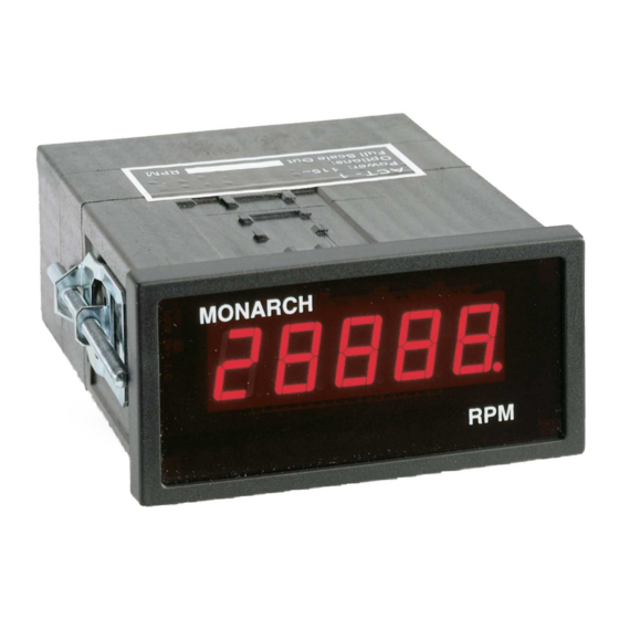
OVERVIEW The ACT-1B is an economical and easy to use digital tachometer that displays rotational speed directly in RPM or RPS on a 5-digit red 0.56” high LED display using a speed sensor providing a single (or multiple) pulse(s) per revolution. -
Page 5: Installation
Installation Remove the mounting clips, if fi tted, and install the unit into the panel from the front. From the rear of the unit, install the mounting clips on each side and tighten the mounting screws against the rear of the panel. WARNING: Do not over tighten the mounting screws. -
Page 6: Usb Programming Cable And Software
USB Programming Cable and Software The 3.5 mm connection “hole” in the center bottom of the rear panel is for the optional USB Programming Cable (p/n 6180-031), which comes with Windows™ compatible PM (Panel Meter) Remote Software. The cable and software combination allows the user to confi... -
Page 7: Output Options
INPUT INPUT INPUT INPUT BLACK WHITE BROWN BROWN BLUE BLUE BLACK Shield to Shield to Link SIG to COM P5-11 ROS-W - OPTICAL SENSOR (SHOWN) AC or TTL M-190W PROXIMITY R0LS-W - REMOTE LASER SENSOR SOURCE MAGNETIC SENSOR IRS-W - INFRARED SENSOR SENSOR MT-190W - AMPLIFIED MAGNETIC SENSOR Figure 3 Sensor Connections... -
Page 8: Current Output Option (Io)
Current Output Option (IO) The current output is 4 to 20 mA. This output is a current source and has a 12 Vdc internal compliance voltage. (Optional 24 Vdc may be ordered). Typical connections are as follows: (See Figure 4.) Connect the Positive side of the load to the terminal marked OUT and the other (Negative) side of the load to the terminal marked COM. -
Page 9: Analog Output Option (Ao)
Analog Output Option (AO) The analog output is 0 to 5 Vdc. Connect the Positive side of the signal to the terminal marked OUT, and the Return side of the signal to the terminal marked COM. NOTE: If your ACT-1B is equipped with either a current output or an analog output, the full-scale output has been factory preset to the speed range specifi... -
Page 10: Specifications
SPECIFICATIONS Range: 5 to 99,999 RPM ±1 RPM or 0.005% of reading Accuracy: 1 RPM (user programmable to 0.0001*) Resolution: Display: 5 digit, 0.56” (14 mm) high red LED Twice per second above 120 RPM (user programmable Display Update: to 0.5, 1, or 1.5 second*) Dimensions: 1/8 DIN by 4.5”... -
Page 11: Options
This product is designed to be safe for indoor use under the following conditions (per IEC61010-1): per IEC 664 Installation Category II per IEC 664 Pollution Degree Level II Operating Temperature 32-122 °F [0-50 °C] Humidity Maximum relative humidity 80% for temperature up to 88 °F [31 °C] decreasing linearly to 50% relative humidity at 104 °F [40 °C] OPTIONS... -
Page 12: Accessories / Sensors
ACCESSORIES / SENSORS Refl ective Tape - 5 foot (1.5 m) roll, 0.5 inch (10 mm) wide USB Programming Cable with PM Remote Software: Enables the user to program the ACT-1B using a PC with USB connection. The software also allows remote monitoring of the RPM using a graphic display or an Excel spreadsheet. -
Page 13: Appendix A - Serial Programming Commands
Appendix A - Serial Programming Commands Programming the unit requires the optional USB Programming Cable with associated PM Remote software and a PC running Windows XP or later with an available USB port. All serial commands are @ then two or more characters or words separated by a delimiter “/”. - Page 14 @CH_A/LOEND = 12 (or 1_SEC, HALF) Sets low end time. This allows a min reading of 5 RPM, 60 RPM, or 120 RPM. @CH_A/GATE Shows Gate Speed. (Default is 12) @CH_A/GATE = STD (1/100 Second) or FAST (1/1000 second). Sets Gate Speed (Default is 1/100) @DECPT Shows the number of decimal places...
- Page 15 This page intentionally left blank.
- Page 16 Check out some of our other product lines… Handheld Frequency Portable Machine Vision Tachometers Converters Stroboscopes Stroboscopes Speed Sensors Temperature/ Vibration Meters Humidity Sensors Paperless Recorders Track-It™ Data Loggers Printed in the U.S.A. Copyright 2009-2019 Monarch Instrument, all rights reserved 1071-4843-113 0519...
Need help?
Do you have a question about the ACT-1B Series and is the answer not in the manual?
Questions and answers