
Subscribe to Our Youtube Channel
Related Manuals for MONARCH INSTRUMENT 6235-010


Summary of Contents for MONARCH INSTRUMENT 6235-010
- Page 1 Instruction Manual Pocket LED Stroboscope 15 Columbia Drive Amherst, NH 03031 USA Phone: (603) 883-3390 • Fax: (603) 886-3300 E-mail: support@monarchinstrument.com Website: www.monarchinstrument.com...
- Page 2 11. This instrument may not be safe for use in certain hazardous environments, and serious personal injury or death could occur as a result of improper use. Please refer to your facility’s safety program for proper precautions. Monarch Instrument’s Limited Warranty applies. www.monarchinstrument.com for details.
- Page 3 This product may be returnable to your distributor for recycling; contact the distributor for details. Manufactured in an ISO9001 facility. For troubleshooting information and technical support visit: www.monarchinstrument.com. Monarch Instrument holds the following US trademarks and registrations, all rights reserved: Track-It™, Nova-Pro ® , Nova-Strobe™, Data-Chart™, illumiNova ®...
-
Page 4: Table Of Contents
TABLE OF CONTENTS INTRODUCTION ................1 USER INTERFACE ................2 GETTING STARTED ................ 3 Power .................. 3 Input/Output Connections ..........3 MODES OF OPERATION ..............4 Internal Strobe Mode ............5 4.1.1 Adjusting the Flash Rate - RPM ........ 5 4.1.2 Doubling or Halving the Flash Rate ...... -
Page 5: Introduction
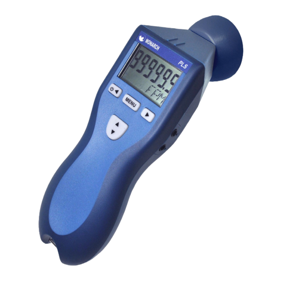
INTRODUCTION The Pocket LED Strobe (PLS) is a rugged, portable battery powered LED (Light Emitting Diode) stroboscope used for inspection and to stop motion to determine the speed of rotating objects. The unit is ergonomically designed for comfortable handheld operation or it may be mounted on a tripod using the integral ¼... -
Page 6: User Interface
USER INTERFACE The Pocket LED Strobe has a two-line backlit alpha-numeric liquid crystal display (LCD) and a four-key keypad that enables the user to control the operation of the unit. The user interface is described in Figure 2 and the table below. -
Page 7: Getting Started
GETTING STARTED The Stroboscope may be hand held or mounted on a tripod or other user supplied bracket using the ¼-20 UNC bushing on the underside of the unit. Power The LED Strobe is battery powered and has internal rechargeable batteries. -
Page 8: Modes Of Operation
Common (GND) Signal Input +3.2V Out to +3.2V Out to Sensor Sensor Signal Input Common (GND) Figure 3 Input Connector Detail (Stereo Plug) Common (GND) Signal Output Common (GND) Figure 4 Output Connector Detail (Mono plug) With no external input, the output jack provides a TTL compatible pulse from the strobe’s internal oscillator. -
Page 9: Internal Strobe Mode
4.1 Internal Mode The strobe is in the Internal Mode when nothing is plugged into the input jack. In the internal mode the strobe generates its own timing signals and the user can adjust the flash rate as described below. 4.1.1 Adjusting the Flash Rate - RPM The flash rate can be adjusted by pressing the large UP/DOWN button. -
Page 10: External Mode
4.2 External Mode In the External Input Mode the user can’t make any flash rate adjustments. The flash rate is a function of the input signal. This mode is used to synchronize the flash to an external event (for example, from an optical sensor) to stop or freeze motion. -
Page 11: Menu Options
SETUP MENU OPTIONS To enter the Setup Mode it is necessary to press the MENU button twice. The first press will enter the x2 /2 mode as described in Section 4.1.2; the second press will enter the Setup Mode. The top line of the display will show SEtUP and the bottom line will show the setup options. -
Page 12: Brite (Brightness)
5.2 BRITE (Brightness) Adjust the flash pulse width and consequently the brightness. See Section 6.0. When the display shows: SEtUP BRITE Press the MENU button to enter. Width can be set in degrees or microseconds. DEG - Set the flash width in degrees from 0.1° to 10.0°. Use the UP/ DOWN button ▲▼... -
Page 13: Load
Press MENU to select, use the UP/DOWN button ▲▼ to select a memory location, press MENU to select the location. The flash rate is shown on the top row, memory location on the bottom row (see below). 600 SM 3 (SM = Save Memory) Press MENU to save and EXIT OUT OF MENU. -
Page 14: Decpt (Decimal Point)
Press MENU to select, use the UP/DOWN button ▲▼ to select on or off. As the status changes, the backlight will activate accordingly. BKLIT Press MENU to save and exit back to the main menu. 5.7 DECPT (Decimal Point) Set the number of decimal places to display. -
Page 15: Strobe Brightness
STROBE BRIGHTNESS The strobe’s brightness depends on how wide the strobe’s flash pulse is; the wider the pulse, the brighter the flash from the LEDs appears to be. There is however, a downside to the wider pulses. All strobes work by giving short bursts of light (the pulse width) at a rapid repetition rate (the flash rate). -
Page 16: Brightness In Degrees Of Rotation
When setting the pulse duration in degrees, what you set is what you get. Refer to the image on the right for the difference between a 1° and 5° (of rotation) flash duration. There are two methods of adjusting the flash pulse width and hence the brightness and consequently the blur. -
Page 17: Using The Stroboscope To Measure Rpm
*Note: There are two limits maintained by the strobe – the pulse can never be greater than 1300 µs nor can it exceed 10° of rotation. The strobe automatically adjusts these values as the flash rate is increased or decreased to maintain these limits at all times. USING THE STROBOSCOPE TO MEASURE RPM The primary use for a stroboscope is to stop motion for diagnostic inspection purposes. - Page 18 Stopped Image 1/4 times 1/2 times 1 time 2 times 3 times 4 times Flash Rate (FPM) 1250 2500 5000 10000 15000 20000 Example: Object Rotating at 3000 RPM If the speed is outside the full scale range of the stroboscope (300,000 FPM), it can be measured using the method of harmonics and multipoint calculation.
-
Page 19: Batteries
BATTERIES The Pocket LED Strobe is fitted with a rechargeable Lithium Ion battery pack. These batteries are prone to self-discharge over time. For maximum performance, charge the batteries prior to use and do not store in hot locations. The strobe uses an external charger. Allow 3-5 cycles of charging and discharging for batteries to reach full capacity. -
Page 20: Battery Disposal
CAUTION: Use of rechargers other than the one supplied (Model LBC-U) will damage the stroboscope and void the warranty. DO NOT LEAVE A CHARGER THAT IS NOT PLUGGED INTO THE AC POWER CONNECTED TO THE STROBE. When charging, the strobe will indicate CHRGE in the bottom right of the display when turned on and then it will shut off. -
Page 21: Specifications
SPECIFICATIONS* Internal Mode Flash Range 30 to 300,000 FPM (Flashes Per Minute), 0.5 to 5000Hz Flash Rate Accuracy 0.005% of setting or ± last digit 0.01 to 1 FPM (menu selectable), 0.1 FPM resolution Flash Rate Resolution above 9,999.99 FPM, 1 FPM resolution above 99,999.9 Display Update Rate Instantaneous External Modes... -
Page 22: Compliance
Adjustable 0.5 to 1300 microseconds or 0.1 to 10 Flash Duration degrees of rotation (auto adjusts with flash rate) Battery powered: internal Li-Ion rechargeable batteries Input Power 3.6VDC Light Output Average: 3300 LUX @6000 FPM 12" from target @ 2° 5 - 6 hours typical at 6000 FPM, and 2.8°... -
Page 23: Sensors/Accessories And Parts
10.0 SENSORS/ACCESSORIES and PARTS See Accessories webpage for details. Sensors/Accessories Model Description 6180-029 ROLS-P Remote Optical Laser Sensor with 8 foot [2.5 m] cable for triggering strobe 6180-081 RLS-P Rugged Laser Sensor with removable cable 6180-057 ROS-P Remote Optical Sensor with 8 foot [2.5 m] cable for triggering strobe 6180-057-25 ROS-P-25... - Page 24 The Professional’s Choice Monarch Instrument is committed to excellence and quality in manufacturing, sales, and service. ™ Track-It Data Loggers Panel Tachometers Portable Tachometers Portable Strobes Frequency Fixed Mounted Converters Strobes Speed Sensors DataChart ™ Paperless Recorders 15 Columbia Drive, Amherst NH 03031 USA Tel.: (603) 883-3390 // Fax: (603) 886-3390...
Need help?
Do you have a question about the 6235-010 and is the answer not in the manual?
Questions and answers