Table of Contents
Advertisement
Available languages
Available languages
Advertisement
Table of Contents

Related Manuals for ABB DCS550-S01


Summary of Contents for ABB DCS550-S01
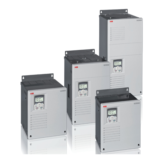
- Page 1 DCS550 Quick Guide DCS550 Drives (20 A to 1000 A)
-
Page 2: Table Of Contents
DCS550 Quick Guide english Contents español Contenido DC Drives Worldwide Service Network ......3 DC Drives Worldwide Service Network ....... 3 DCS550 Manuals ............... 4 DCS550 Manuals / Manuales de DCS550 ......4 DCS550 DC Drives ............. 5 Convertidores de CC DCS550 ......... 49 Brief instructions for CD and documents overview ..... -
Page 3: Dc Drives Worldwide Service Network
ABB Drive Service Pour offrir la même qualité de service à tous nos clients, ABB a créé DRIVE SERVICE CONCEPT. Dans le monde entier, les équipes de service proposent les mêmes presta- tions aux mêmes conditions avec les mêmes objectifs. -
Page 4: Dcs550 Manuals
DCS550 Manuals Language Public. number Quick Guide 3ADW000395 DCS550 Tools & Documentation CD 3ADW000377 DCS550 Modules DCS550 Flyer 3ADW000374 DCS550 Technical Catalog 3ADW000378 DCS550 Manual 3ADW000379 DCS550 Service Manual 3ADW000399 Installation according to EMC 3ADW000032 Technical Guide 3ADW000163 Extension Modules RAIO-01 Analog IO Extension 3AFE64484567 RDIO-01 Digital IO Extension... - Page 5 Standard Features − compact − highest power ability − simple operation − comfortable assistants, e.g. for autotuning or commissioning 3ADW000395R0100 DCS550 Quick guide edisf a 3ADW000395R0100 DCS550 Quick guide edisf a...
-
Page 6: Dcs550 Dc Drives
Supply voltage max. field Dimensions size rated Current rated Current current DCS550-S01 DCS550-S02 internal h x w x d [mm] h x w x d [inch] 370 x 270 x 208 14.56 x 10.65 x 8.20 370 x 270 x 264 14.56 x 10.65 x 10.40... -
Page 7: Brief Instructions For Cd And Documents Overview
Brief instructions for CD and documents overview We appreciate that you purchased an ABB DC drive power System requirements to use the CD-ROM converter and thank you for the trust you put in our products. This brochure was put together to make sure that you con- −... -
Page 8: Notes On Emc
Notes on EMC You will find further informa- The paragraphs below describe selection The EMC Guideline expects EMC to be taken tion in publication: of the electrical components in conformity into account when a product is being devel- with the EMC Guideline. oped;... - Page 9 For compliance with the protection ob- For emitted interference, the following apply: jectives of the German EMC Act (EMVG) EN 61000-6-3 Specialised basic standard for emissions in light industry in systems and machines, the following can be satisfied with special features (mains filters, EMC standards must be satisfied: screened power cables) in the lower rating range *(EN 50081-1).
-
Page 10: Standard Function Assignments For The Terminals
Standard function assignments for the terminals Resolution Input/output Scaling Common Remarks SDCS-CON-F Firmware [bit] values mode Hardware range ±90...±270 V X1:1 ±30...±90 V 15 + sign ±90...270 V ±15 V ① ±30...90 V Firmware ±8...±30 V ATACH ±8...30 V 4 250 15 + sign -10...0...+10 V Firmware... -
Page 11: Connection Example
Connection example Converters F1...F4 drive configuration using ‘OnBoard‘ field exciter Terminal selection according FACTORY macro (default) 3ADW000395R0100 DCS550 Quick guide edisf a 3ADW000395R0100 DCS550 Quick guide edisf a... - Page 12 START, STOP and E-STOP control If the drive has not finished the function within the K15 timer The relay logic can be split into three parts: setting, the drive must get the command to switch OFF the current via K16. After K16 timer set has elapsed the main a: Generation of the ON/OFF and START/STOP command: contactor is opened independent of the drives status.
-
Page 13: Fan Power Connection
Fan power connection Fan assignment for DCS550 Converter type Model Configuration Fan voltage DCS550-S01-0020, ..., no fan, convection cooled DCS550-S02-0025 DCS550-S01-0045, ..., 1 x 3110KL-05W... (internal 24 V DCS550-S02-0100 DCS550-S01-0135, ..., 2 x 4715MS (115 / 230 V DCS550-S02-0300 DCS550-S01-0315, ...,... -
Page 14: Terminal Locations On The Converter
Terminal locations on the converter D2002 D1000 1 2 3 4 5 6 7 8 9 10 1 2 3 4 5 6 7 8 9 10 1 2 3 4 5 6 7 8 9 10 1 2 3 4 5 6 7 8 9 10 1 2 3 4 5 6 7 8 DCS550 terminal alloc_c.dsf Macro finder Enabling a macro... -
Page 15: Notes For North American Installations
Step 1: This is to protect the motor and converter if a commutation Check converter for damage. Contact ABB Technical Support fault should occur. NOTE: DC output fuses are the same type if damage is found. In North America, call 1-800-435-7365 and size as AC line fuses. - Page 16 Step 3: − You will select the macro and / or choose the configuration for digital and analog inputs and outputs in step 2 of the Mount and wire the converter and supporting hardware inside commissioning process, or by updating group 10 and 14 an industrial enclosure with adequate cooling (DCS550 mod- parameters.
-
Page 17: Safety And Operating Instructions
Safety and operating instructions for drive converters DCS / DCF / DCR (in conformity with the low-voltage directive 73/23/EEC) 1. General 4. Installation In operation, drive converters, depending on their degree of The installation and cooling of the appliances shall be in ac- protection, may have live, uninsulated, and possibly also mov- cordance with the specifications in the pertinent documenta- ing or rotating parts, as well as hot surfaces. -
Page 18: Installing The Dcs550 Pc Tools On Your Computer
2. Hitachi FDT 2.2 for firmware download 3. Installation CD of DCS550 Drive for e.g. DWL Wizard, ABB documents Attention: If You do not want to install a certain program just skip it by using Cancel at the beginning of the program’s wizard. -
Page 19: Commissioning
Commissioning Danger! High voltage: this symbol warns of high General instructions voltages which may result in injuries to persons − This short commissioning refers to chapter Connection and/or damage to equipment. Where appropriate, examples of this publication. the text printed adjacent to this symbol describes −... -
Page 20: Dcs550 Control Panel
DCS550 Control Panel The following table summarizes the button functions and displays of the DCS550 Control Panel DCS800 QG pan ov_c.dsf With USISel (16.09) it is possible to limit the amount of displayed parameters! General display features Parameters entered by assistant Following modes are available in the MAIN MENU: Parameters mode 99.02... - Page 21 Standard Features − kompakt − Höchste Leistungsfähigkeit − Einfachste Bedienung − Komfortable Assistenten, z. B. zur Inbetriebnahme oder Fehlersuche 3ADW000395R0100 DCS550 Quick guide edisf a 3ADW000395R0100 DCS550 Quick guide edisf a...
-
Page 22: Dcs550 Gleichstromantriebe
Versorgungs max. Abmessungens größe Dauerstrom Dauerstrom spannung Feldstrom DCS550-S01 DCS550-S02 intern h x b x t [mm] h x b x t [inch] 370 x 270 x 208 14.56 x 10.65 x 8.20 370 x 270 x 264 14.56 x 10.65 x 10.40 459 x 270 x 310 18.07 x 10,65 x 12,25... -
Page 23: Kurzanweisung Cd Und Dokumentationsübersicht
Kurzanweisung CD und Dokumentationsübersicht Wir freuen uns, dass Sie einen ABB DC-Stromrichter erwor- Systemvoraussetzungen für die Nutzung der CD ROM ben haben und bedanken uns für das Vertrauen, welches Sie unseren Produkten entgegengebracht haben. − Betriebssystem Damit Sie auch weiterhin mit unserem Produkt zufrieden sind,... -
Page 24: Emv Filter
EMV Filter Weitere Informationen Nachfolgend wird die Auswahl der elekt- Die EMV-Richtlinie verlangt, dass die EMV hierzu siehe: rischen Komponenten entsprechend der bereits bei der Produktentwicklung berücksich- EMV-Richtlinie beschrieben. tigt werden muss; jedoch kann die EMV nicht Technical Guide Kapitel: Ziel der EMV-Richtlinie ist es, eine elekt- mit eingeplant werden, sie kann nur quantitativ EMC Compliant Installation... - Page 25 Um bei Maschinen und Anlagen die Normen für Störabstrahlungen: Schutzvorgaben des deutschen EMV- EN 61000-6-3 Die spezielle Basisnorm für Abstrahlungen in der Leichtindustrie Gesetzes (EMVG) erfüllen zu können, kann mit speziellen Einrichtungen (Netzfiltern, geschirmten Kabeln) müssen folgende EMV-Normen einge- im unteren Leistungsbereich erfüllt werden *(EN 50081-1). halten werden: EN 61000-6-4 Spezielle Basisnorm für Abstrahlungen in der Industrie...
-
Page 26: Digitaler Und Analoger E-A/Anschluss Von Sdcs-Con-F
Digitaler und analoger E/A-Anschluss von SDCS-CON-F Auflösung Ein-/Ausgangs- Skalierung Gleich- Anmerkungen werte SDCS-CON-F [bit] durch takt- Firmware Hardware bereiche ±90...±270 V X1:1 15 + Vor- ±90...270 V ±15 V ① ±30...±90 V zeichen ±30...90 V Firmware ±8...±30 V ±8...30 V ATACH 4 250 15 + Vor-... -
Page 27: Anschlussbeispiel
Anschlussbeispiel Stromrichter F1...F4 mit ‘On Board‘ Felderreger Die Verdrahtung des Stromrichters entpricht dem Macro FACTORY (default) 3ADW000395R0100 DCS550 Quick guide edisf a 3ADW000395R0100 DCS550 Quick guide edisf a... - Page 28 START, STOP und NOT-AUS-Steuerung Wenn NOT-AUS (Not-Halt) gedrückt wird, wird die Meldung Die Relaislogik kann in drei Teile untergliedert werden: über Digitaleingang DI5 an den Stromrichter gesendet. Bei Rampenstopp oder max. Drehmoment verzögert der Strom- a: Ausgabe des EIN/AUS- und START/STOPP-Befehls: richter den Motor und öffnet dann das Hauptschütz.
-
Page 29: Lüfterkühlung
Lüfterkühlung Lüfterzuordnung für DCS550 Stromrichtertyp Model Konfiguration Lüfterspannung DCS550-S01-0020, ..., kein Lüfter DCS550-S02-0025 DCS550-S01-0045, ..., 1 x 3110KL-05W... (intern 24 V DCS550-S02-0100 DCS550-S01-0135, ..., 2 x 4715MS (115 / 230 V DCS550-S02-0300 DCS550-S01-0315, ..., 2 x 4715MS (115 / 230 V DCS550-S02-0450 DCS550-S01-0470, ...,... -
Page 30: Klemmen- Und Steckeranordnung Des Stromrichters
Klemmen- und Steckeranordnung des Stromrichters D2002 D1000 1 2 3 4 5 6 7 8 9 10 1 2 3 4 5 6 7 8 9 10 1 2 3 4 5 6 7 8 9 10 1 2 3 4 5 6 7 8 9 10 1 2 3 4 5 6 7 8 DCS550 terminal alloc_c.dsf Macro finder Macro auswählen... -
Page 31: Sicherheits- Und Anwendungshinweise
Sicherheits- und Anwendungshinweise für Antriebsstromrichter DCS / DCF / DCR (gemäß: Niederspannungsrichtlinie 73/23/EWG)) 1. Allgemein 4. Aufstellung Während des Betriebes können Antriebsstromrichter ihrer Die Aufstellung und Kühlung der Geräte muss entsprechend Schutzart entsprechend spannungsführende, blanke, gegebe- den Vorschriften der zugehörigen Dokumentation erfolgen. nenfalls auch bewegliche oder rotierende Teile, sowie heiße Oberflächen besitzen. -
Page 32: Installation Der Dcs550 Programme Auf Dem Pc
DCS550 add ons wird empfohlen Verbindung zum Antrieb herstellen − Die COM Adresse des USB Adapters kann sich nach dem − Die Dokumentation kann unter C:\ABB\DCS550\Docu nächsten Booten oder bei erneutem Anschluss ändern. gefunden werden − Den Gerätedeckel vom Stromrichtermodul entfernen... -
Page 33: Inbetriebnahme
Inbetriebnahme Vorsicht! Hochspannung: Dieses Symbol warnt Allgemeine Hinweise vor hohen Spannungen, die eine Verletzungsgefahr − Diese Kurzinbetriebnahme bezieht sich auf Kapitel An- darstellen und/oder Schäden an der Anlage schlussbeispiele dieser Druckschrift. verursachen können. Neben dem Symbol werden − Sicherheits- und Anwendungshinweise - Kapitel dieser ggf. -
Page 34: Dcs550 Steuertafel
DCS550 Steuertafel In der folgenden Abbildung sind die Tastenfunktionen und Anzeigen der DCS550-Steuertafel dargestellt. DCS800 QG pan ov_c.dsf Mit USISel (16.09) ist es möglich die Menge der Parameter, die angezeigt werden, zu reduzieren. Allgemeine Displayfunktionen Parameter, die über den Assistenten eingegeben werden Folgende Modi sind im HAUPMENÜ... - Page 35 Caratteristiche Standard − Compatto − Per alta potenza − Semplice da usare − Assistente comodo, es. per autotaratura e messa in servizio 3ADW000395R0100 DCS550 Quick guide edisf a 3ADW000395R0100 DCS550 Quick guide edisf a...
-
Page 36: Dcs550 Dc Drives
Tensione di rete Corrente Dimensioni unità nominale nominale max. cam- DCS550-S01 DCS550-S02 po internol h x w x d [mm] h x w x d [inch] 370 x 270 x 208 14.56 x 10.65 x 8.20 370 x 270 x 264 14.56 x 10.65 x 10.40... -
Page 37: Brevi Istruzioni Cd E Documentazione Panoramica
Brevi istruzioni per CD ed informazioni generali sui documenti La ringraziamo per l’acquisto di un convertitore di potenza Requisiti di sistema per l’utilizzo del CD-ROM per azionamenti in cc ABB e per la fiducia accordata ai nostri prodotti. − Sistema operativo... -
Page 38: Note Sulle Emc
Note sulla EMC Troverai ulteriori informazioni Il seguente paragrafo descrive la selezione La nornativa EMC prevede che gli aspetti relativi nella pubblicazione: di componenti elettrici in conformità alla alla compatibilità elettromagnetica siano valutati normativa EMC. già nella fase di sviluppo del prodotto; tutta- Technical Guide chapter: Lo scopo di tale normativa, consiste via non è... - Page 39 Per assicurare la conformità agli obiettivi Per quanto riguarda le interferenze emesse, sono applicabili le seguenti norme: di protezione della legge tedesca sulla EN 61000-6-3 Norma specifica di base per emissioni nell‘ambito dell‘industria compatibilità elettromagnetica (EMVG) leggera che può essere rispettata con dispositivi speciali (filtri di in sistemi e macchine, devono essere rete, cavi di potenza schermati) nelle gamme di potenza inferiori rispettate le seguenti norme sulla com-...
-
Page 40: Assegnazione Funzioni Standard Per I Morsetti
Assegnazioni funzioni standard per I morsetti Risoluzione Valori Input/ Regolabile Scala Note SDCS-CON-F Firmware [bit] Output ±90...±270 V Hardware X1:1 ±30...±90 V 15 + sign ±90...270 V ±15 V ① ±30...90 V Firmware ±8...±30 V ATACH ±8...30 V 15 + sign -10...0...+10 V Firmware ±15 V... -
Page 41: Esempi Schemi Di Collegamento
Esempio di collegamento Configurazione dell‘azionamento convertitori F1 … F4 con eccitatrice di campo interna Selezione dei terminali secondo la macro FACTORY (default) 3ADW000395R0100 DCS550 Quick guide edisf a 3ADW000395R0100 DCS550 Quick guide edisf a... - Page 42 Controllo di START, STOP e E-STOP In caso di selezione di E-STOP, l’informazione è trasferita al La logica a relè può essere divisa in tre parti: convertitore tramite l’ingresso digitale 5. In caso di (arresto con funzione di rampa o in limitazione di corrente) il converti- a: Generazione del comandi di ON/OFF e START/STOP: tore decelererà...
-
Page 43: Ventole Di Raffreddamento
Ventole di raffreddamento Tipi di ventole per i DCS550 Unità DCS Modello Configurazione Ventole DCS550-S01-0020, ..., no fan DCS550-S02-0025 DCS550-S01-0045, ..., 1 x 3110KL-05W... (internal 24 V DCS550-S02-0100 DCS550-S01-0135, ..., 2 x 4715MS (115 / 230 V DCS550-S02-0300 DCS550-S01-0315, ...,... -
Page 44: Posizioni Terminali Sul Convertitore
Posizioni terminali sul convertitore D2002 D1000 1 2 3 4 5 6 7 8 9 10 1 2 3 4 5 6 7 8 9 10 1 2 3 4 5 6 7 8 9 10 1 2 3 4 5 6 7 8 9 10 1 2 3 4 5 6 7 8 DCS550 terminal alloc_c.dsf Macro finder Abilitare una macro... -
Page 45: Istruzioni Per La Sicurezza
Istruzioni per la sicurezza per convertitori in c.c. DCS / DCF / DCR (secondo: Direttiva Bassa Tensione 73/23/CEE) 1. Prescrizioni generali 4. Montaggio Convertitori in c.c. relativo al loro grado di protezione possono Per il montaggio ed il raffreddamento degli apparecchi devono avere durante il funzionamento parti sotto tensione non isolati, essere rispettate le prescrizioni contenute nella documenta- parti mobili o rotanti e superfici con temperature elevati. -
Page 46: Installa I Dcs550 Pc Tools Sul Tuo Computer
1. DriveWindow Light per parametrizzazione, messa in servizio e service 2. Hitachi FDT 2.2 per caricamento firmware 3. Installazione CD del DCS550 Drive per es. DWL Wizard, documentazione ABB Attenzione: Se non vuoi installare un certo programma devi solamente saltarlo usando Cancel all’inzio del programma wizard. -
Page 47: Messa In Servizio
Messa in servizio Pericolo! Alta tensione: questo simbolo indica la Istruzioni generali presenza di alta tensione che può provocare − Questa breve routine di messa in servizio si riferisce allo lesioni alle persone e/o Danni alle apparecchiature. schema di collegamento contenuto nel Capitolo di questa Il testo accanto al simbolo illustra eventuali pubblicazione. -
Page 48: Dcs550 Pannello Di Controllo
DCS550 Pannello di controllo La seguente tabella elenca le funzioni dei pulsanti e le visualizzazioni del DCS550 Control Panel. DCS800 QG pan ov_c.dsf Con USISel (16.09) è possibile limitare il quantitativo di parametri visualizzati! Caratteristiche generali del display Parameters entered by assistant Le seguenti modalità... - Page 49 Características de serie − compacto − alta capacidad de potencia − operación simples − asistentes confortables, p. ej. puesta en funcionamiento y ajuste automático 3ADW000395R0100 DCS550 Quick guide edisf a 3ADW000395R0100 DCS550 Quick guide edisf a...
-
Page 50: Convertidores De Cc Dcs550
Corriente Corriente mentación te máx. nomina nominal excitación DCS550-S01 DCS550-S02 interna al. x an. x pr. [mm] al. x an. x pr. [inch] 370 x 270 x 208 14.56 x 10.65 x 8.20 370 x 270 x 264 14.56 x 10.65 x 10.40 459 x 270 x 310 18.07 x 10,65 x 12,25... -
Page 51: Instrucciones Para El Cd Y De La Documentación
Información para el mantenimiento y reparación de los con- Si necesita cualquier información adicional, póngase en vertidores. contacto con su oficina ABB Drives más cercana o envíe un correo electrónico a: La información adicional acerca de aplicaciones y acceso- rios técnicos (p. ej. ampliación de hardware o interfases de DC-Drives@de.abb.com... -
Page 52: Notas Acerca De Emc
Notas acerca de la EMC Encontrará información adi- Los siguientes párrafos describen la Las directrices EMC esperan que durante el cional en la publicación: selección de los componentes eléctricos desarrollo de un producto se tengan en cuenta conforme a las directrices de compatibili- las recomendaciones para EMC;... - Page 53 Para la conformidad con los objetivos Para la emisión de interferencias se aplica lo siguiente: de protección del acta alemana de EMC EN 61000-6-3 Norma básica especializada para emisiones en la industria ligera (EMVG) en máquinas y sistemas, deben que puede cumplirse con características especiales (filtros de red, cumplirse las siguientes normas EMC: cables de potencia apantallados) en las especificaciones nominales más bajas *(EN 50081-1).
-
Page 54: Asignaciones De Funciones Estándar Para Los Terminales
Asignaciones de funciones estándar para los terminales Resolución Valores de Escalado Rango de Comentarios SDCS-CON-F Firmware [bits] entrada/salida mediante modo ±90...±270 V Hardware común X1:1 ±30...±90 V 15 + señal ±90...270 V ±15 V ① ±30...90 V Firmware ±8...±30 V ATACH ±8...30 V 4 250... -
Page 55: Ejemplo De Conexión
Ejemplo de conexión Configuración de los convertidores F1...F4 utilizando un excitador de campo‚ incorporado‘ Selección del terminal según la macro de fábrica (FACTORY) (por defecto) 3ADW000395R0100 DCS550 Quick guide edisf a 3ADW000395R0100 DCS550 Quick guide edisf a... - Page 56 Control de marcha, paro y paro de emergencia (E-STOP) En caso de que se pulse el botón de paro de emergencia, la La lógica de relé puede dividirse en tres partes: información se transfiere al convertidor a través de la entra- da digital 5.
-
Page 57: Conexión De Alimentación Del Ventilador
Conexión de alimentación del ventilador Asignación de ventiladores para DCS550 Tipo de convertidor Modelo Configuración Tensión del ventilado DCS550-S01-0020, ..., sin ventilador DCS550-S02-0025 DCS550-S01-0045, ..., 1 x 3110KL-05W... (internal 24 V DCS550-S02-0100 DCS550-S01-0135, ..., 2 x 4715MS (115 / 230 V DCS550-S02-0300 DCS550-S01-0315, ...,... -
Page 58: Ubicación De Los Terminales En El Convertidor
Ubicación de los terminales en el convertidor D2002 D1000 1 2 3 4 5 6 7 8 9 10 1 2 3 4 5 6 7 8 9 10 1 2 3 4 5 6 7 8 9 10 1 2 3 4 5 6 7 8 9 10 1 2 3 4 5 6 7 8 DCS550 terminal alloc_c.dsf Macro finder Habilitar un macro... -
Page 59: Instrucciones De Seguridad
Instrucciones de seguridad para convertidores de accionamiento DCS / DCF / DCR (según: directriz de baja tensión 73/23/CEE) 1. General 4. Instalación Durante el servicio los convertidores de accionamiento pue- La instalación y la refrigeración de los aparatos han de ser den - según su tipo de protección - tener partes conduciendo ejecutadas según las especificaciones de la documentación corrientes, desnudos y dado el caso también partes móviles y... -
Page 60: Cómo Instalar Las Herramientas Para Pc Del Dcs550
2. Hitachi FDT 2.2 para la descarga del firmware 3. CD de instalación del convertidor DCS550, p. ej. el asistente DWL y documentos de ABB Atención: Si no desea instalar un programa en concreto, simplemente ignórelo mediante la opción cancelar (Cancel) al inicio del asistente del programa. -
Page 61: Puesta En Funcionamiento
Puesta en funcionamiento ¡Peligro! Alta tensión: este símbolo previene de Instrucciones generales altas tensiones que pueden causar lesiones físicas − Esta puesta en funcionamiento corta hace referencia al y/o daños al equipo. Cuando procede, el texto Capítulo Ejemplos de conexión de esta publicación. impreso al lado de este símbolo describe cómo −... -
Page 62: Panel De Control Del Dcs550
Panel de control del DCS550 La siguiente tabla resume las funciones de los botones y la muestra del Panel de Control del DCS550. DCS800 QG pan ov_c.dsf Con USISel (16.09) puede limitarse la cantidad de parámetros visualizados Características generales de la pantalla Parámetros introducidos por el asistente Los modos disponibles en el menú... - Page 63 La performance en standard − Compacité − Puissance − Simplicité − Convivialité (autocalibrage des régulateurs et assistants de mise en service) 3ADW000395R0100 DCS550 Quick guide edisf a 3ADW000395R0100 DCS550 Quick guide edisf a...
-
Page 64: Variateurs À Courant Continu Dcs550
Taille Tension réseau Courant Dimensions Courant nom. Courant nom. maxi excit. DCS550-S01 DCS550-S02 interne h x l x p [mm] h x l x p [pouce] 370 x 270 x 208 14.56 x 10.65 x 8.20 370 x 270 x 264 14.56 x 10.65 x 10.40... -
Page 65: Documentation Technique
Documentation technique Vous avez acheté un variateur à courant continu ABB ; nous − ACROBAT READER vous remercions de votre confiance et mettons tout en œuvre pour vous satisfaire. Ce mémento a été rédigé pour vous aider à tirer le meilleur de Si le CD-ROM ne démarre pas... -
Page 66: Compatibilité Électromagnétique (Cem)
Compatibilité électromagnétique (CEM) Pour en savoir plus, cf. do- Nous décrivons ci-après le mode de sé- Les normes CEM supposent que le cument: lection des composants conformément comportement CEM d’un produit est pris aux normes de CEM. en compte au stade de son développe- Technical Guide, chapitre : L’objectif de la CEM est, d’assurer la ment. - Page 67 Pour obtenir la protection CEM des Pour les limites d’émissions, les normes suivantes s’appliquent: systèmes et machines, les exigences EN 61000-6-3 Norme générique Emissions, environnement d’industrie légère, des normes CEM suivantes doivent être exigences respectées avec des dispositifs spéciaux (filtres réseau, satisfaites: câbles de puissance blindés) pour les faibles puissances.
-
Page 68: Raccordement Standard Des Signaux D'e/S
Raccordement standard des signaux d’E/S Résolution Valeur des Réglage Plage de Remarques SDCS-CON-F [bit] entrées/ mode Firmware sorties commun ±90...±270 V X1:1 15 + sign ±90...270 V ±15 V ① ±30...±90 V ±30...90 V Paramètre ±8...±30 V ATACH ±8...30 V 4 250 15 + sign -10...0...+10 V... -
Page 69: Exemple De Schéma De Câblage
Exemple de schéma de câblage Configuration d’un variateur de taille F1 à F4 avec excitation intégrée Préréglage des paramètres du macroprogramme USINE 3ADW000395R0100 DCS550 Quick guide edisf a 3ADW000395R0100 DCS550 Quick guide edisf a... - Page 70 Signaux de commande DEMARRAGE, ARRET et ARRET Si le bouton d’arrêt d’urgence (E-STOP) est activé, l’informa- tion est transmise au convertisseur via l’entrée logique DI5. Si URGENCE La logique de commande peut être divisée en trois parties: un arrêt sur rampe ou par la limite de couple est sélectionné, le variateur décélérera le moteur et le contacteur principal a: Génération des signaux ENC/DECL et DEMAR/ARRET: s’ouvrira.
-
Page 71: Câblage Du Ventilateur
Câblage du ventilateur Type de ventilateur DCS550 Type de convertisseur Taille Configuration Tension ventilateur DCS550-S01-0020, ..., sans ventilateur DCS550-S02-0025 DCS550-S01-0045, ..., 1 x 3110KL-05W... (internal 24 V DCS550-S02-0100 DCS550-S01-0135, ..., 2 x 4715MS (115 / 230 V DCS550-S02-0300 DCS550-S01-0315, ...,... -
Page 72: Emplacement Des Bornes Sur Le Convertisseur
Emplacement des bornes sur le convertisseur D2002 D1000 1 2 3 4 5 6 7 8 9 10 1 2 3 4 5 6 7 8 9 10 1 2 3 4 5 6 7 8 9 10 1 2 3 4 5 6 7 8 9 10 1 2 3 4 5 6 7 8 DCS550 terminal alloc_c.dsf Macro finder Faire une macro... -
Page 73: Consignes De Sécurité Et D'exploitation
Consignes de sécurité et d’exploitation pour les convertisseurs DCS / DCF / DCR (conformes à la directive Basse Tension 73/23/CEE) 1. Généralités 4. Installation Selon leur degré de protection, les convertisseurs en fonc- L’installation et le refroidissement des appareils doivent tionnement peuvent comporter des parties nues sous tension respecter les consignes de la documentation fournie avec le ainsi que des pièces en mouvement ou en rotation, et des... -
Page 74: Installation Des Outils Logiciels Du Dcs550 Sur Votre Pc
2. Hitachi FDT 2.2 pour le chargement du logiciel (firmware) 3. CD d’installation du variateur DCS550 (ex., assistant DWL, documents ABB) Attention: Si vous ne désirez pas installer un programme donné, cliquez sur Annuler (Cancel) au début de l’assistant du programme concerné... -
Page 75: Mise En Service
Mise en service Danger ! Haute tension: des tensions élevées Généralités peuvent provoquer des blessures graves et/ou − Ce démarrage rapide se réfère au Chapitre Exemple de endommager le matériel. Le texte qui se rapporte schéma de câblage de ce mémento. à... -
Page 76: Micro-Console Dcs550
Micro-console DCS550 Description succincte des touches fonctionnelles et de l’affichage de la micro-console du DCS550. LED d’état : Référence locale - modification avec • verte allumée : fonctionnement normal touches à flèche (haut/bas) • verte clignotante : alarme • rouge : défaut Signal - sélectionné... -
Page 77: Dimensions, Drilling Patterns And Weights
Dimensions, drilling patterns and weights — Abmessungen, Bohrbild und Gewichte — Dimensioni, schemi di foratura e pesi — Dimensiones, patrones de taladrado y pesos — Dimensions, perçages et poids Module F1 Dimensions in mm DCS550-S01-0020 Maße in mm DCS550-S01-0045 Dimensioni in mm DCS550-S01-0065 Dimensiones en mm... - Page 78 Air direction Module F4 DCS550-S01-0610 Luftrichtung DCS550-S01-0740 Direzione aria DCS550-S01-0900 Dirección del aire Sens de circulation de l‘air DCS550-S02-0680 DCS550-S02-0820 DCS550-S02-1000 Weight appr. 38 kg 3ADW000395R0100 DCS550 Quick guide edisf a...
- Page 79 Top view air outlet / air duct — Draufsicht Luftaustritt / Luftschacht — Vista dall‘alto uscita aria / condotto di aria — Vista en planta salida de aire / conductos de aire — Vue de dessus sortie d‘air / conduits d‘air 3ADW000395R0100 DCS550 Quick guide edisf a...
-
Page 80: Fault / Alarm List
3ADW000395R0100 DCS550 Quick guide edisf a 3ADW000395R0100 DCS550 Quick guide edisf a... - Page 81 3ADW000395R0100 DCS550 Quick guide edisf a 3ADW000395R0100 DCS550 Quick guide edisf a...
- Page 82 3ADW000395R0100 DCS550 Quick guide edisf a 3ADW000395R0100 DCS550 Quick guide edisf a...
- Page 83 3ADW000395R0100 DCS550 Quick guide edisf a 3ADW000395R0100 DCS550 Quick guide edisf a...
- Page 84 3ADW000395R0100 DCS550 Quick guide edisf a 3ADW000395R0100 DCS550 Quick guide edisf a...
- Page 85 3ADW000395R0100 DCS550 Quick guide edisf a 3ADW000395R0100 DCS550 Quick guide edisf a...
-
Page 86: Diagnosis Messages
3ADW000395R0100 DCS550 Quick guide edisf a 3ADW000395R0100 DCS550 Quick guide edisf a... - Page 87 3ADW000395R0100 DCS550 Quick guide edisf a 3ADW000395R0100 DCS550 Quick guide edisf a...
- Page 88 3ADW000395R0100 DCS550 Quick guide edisf a 3ADW000395R0100 DCS550 Quick guide edisf a...
- Page 89 3ADW000395R0100 DCS550 Quick guide edisf a 3ADW000395R0100 DCS550 Quick guide edisf a...
- Page 90 3ADW000395R0100 DCS550 Quick guide edisf a 3ADW000395R0100 DCS550 Quick guide edisf a...
-
Page 91: Macro & Firmware Structure
Macro & Firmware structure – Makro & Firmware Struktur – Struttura macro & firmware – Estructura del macro & firmware – Structure du logiciel macro & système α ≥ DCS550_macros_b.dsf 3ADW000395R0100 DCS550 Quick guide edisf a 3ADW000395R0100 DCS550 Quick guide edisf a... - Page 92 α ≥ DCS550_macros_b.dsf 3ADW000395R0100 DCS550 Quick guide edisf a 3ADW000395R0100 DCS550 Quick guide edisf a...
- Page 93 α ≥ DCS550_macros_b.dsf 3ADW000395R0100 DCS550 Quick guide edisf a 3ADW000395R0100 DCS550 Quick guide edisf a...
- Page 94 α ≥ DCS550_macros_b.dsf 3ADW000395R0100 DCS550 Quick guide edisf a 3ADW000395R0100 DCS550 Quick guide edisf a...
- Page 95 α ≥ DCS550_macros_b.dsf 3ADW000395R0100 DCS550 Quick guide edisf a 3ADW000395R0100 DCS550 Quick guide edisf a...
- Page 96 α ≥ DCS550_macros_b.dsf 3ADW000395R0100 DCS550 Quick guide edisf a 3ADW000395R0100 DCS550 Quick guide edisf a...
- Page 97 α ≥ DCS550_macros_b.dsf 3ADW000395R0100 DCS550 Quick guide edisf a 3ADW000395R0100 DCS550 Quick guide edisf a...
- Page 98 α ≥ DCS550_macros_b.dsf 3ADW000395R0100 DCS550 Quick guide edisf a 3ADW000395R0100 DCS550 Quick guide edisf a...
- Page 99 α ≥ DCS550_macros_b.dsf 3ADW000395R0100 DCS550 Quick guide edisf a 3ADW000395R0100 DCS550 Quick guide edisf a...
- Page 100 α ≥ DCS550_macros_b.dsf 3ADW000395R0100 DCS550 Quick guide edisf a 3ADW000395R0100 DCS550 Quick guide edisf a...
- Page 101 3ADW000395R0100 DCS550 Quick guide edisf a 3ADW000395R0100 DCS550 Quick guide edisf a...
- Page 102 3ADW000395R0100 DCS550 Quick guide edisf a 3ADW000395R0100 DCS550 Quick guide edisf a...
- Page 103 3ADW000395R0100 DCS550 Quick guide edisf a 3ADW000395R0100 DCS550 Quick guide edisf a...
-
Page 104: Declaration Of Conformity
3ADW000395R0100 DCS550 Quick guide edisf a... -
Page 105: Declaration Of Incorporation
3ADW000395R0100 DCS550 Quick guide edisf a... - Page 106 3ADW000395R0100 DCS550 Quick guide edisf a...
- Page 107 DCS family DCS550-S modules Compact ▅ The compact drive for Robust design ▅ Adaptive and winder program machinery application ▅ High field exciter current ▅ … 1,000 A … 610 V 230 … 525 V IP00 DCS800-S modules Compact ▅ The versatile drive for Highest power ability ▅...
- Page 108 Contact us ABB Automation Products GmbH Motors & Drives Wallstadter Straße 59 D-68526 Ladenburg Germany Telefon +49 (0)6203 717 717 Telefax +49 (0)6203 717 600 Service-Tel. 01805 222 580 motors.drives@de.abb.com www.abb.de/motors&drives...
Need help?
Do you have a question about the DCS550-S01 and is the answer not in the manual?
Questions and answers