ABB DCS880 Series Hardware Manual
20...5200 a
Hide thumbs
Also See for DCS880 Series:
- Service manual (128 pages) ,
- Hardware manual (84 pages) ,
- Quick manual (46 pages)
Table of Contents
Advertisement
Quick Links
Advertisement
Table of Contents

Related Manuals for ABB DCS880 Series


Summary of Contents for ABB DCS880 Series
- Page 1 DCS880 Hardware manual DCS880 Drives (20 ... 5200 A)
-
Page 2: Dcs880 Drive Manuals
DCS880 Drive manuals Language Publication number General 3ADW000480 DCS880 Quick guide Safety instructions all languages 3ADW000481 DCS880 Documentation pack DCS880 CD download DCS880 Units 3ADW000475 DCS880 Flyer 3ADW000465 DCS880 Technical catalog 3ADW000462 DCS880 Hardware manual 3ADW000474 DCS880 Firmware manual 3ADW000488 DCS880 Service manual DCS880 Hardparallel manual 3ADW000530... - Page 3 DCS880 Drives 20 ... 5200 A Hardware manual Code: 3ADW000462R0401 Rev D Effective: 01.2019 Supersedes: 01.2018 2019 ABB Automation Products GmbH. All rights reserved. 3ADW000462R0401 DCS880 Hardware manual e d...
-
Page 4: Table Of Contents
Table of contents DCS880 Drive manuals ............2 Table of contents Safety instructions What this chapter contains . - Page 5 Unit above another ............31 Terminal options for converter modules size H1 ...
- Page 6 Connecting a control unit at H7 and H8 power units ........76 Installation checklist Maintenance Chapter overview .
- Page 7 Cables ..............102 Measuring board SDCS-PIN-H51 (H6 ...
- Page 8 Semiconductor fuses and fuse holders for AC and DC power lines ....150 Line reactors IEC............. . . 151 Line reactors type ND01 ...
-
Page 9: Safety Instructions
Safety instructions What this chapter contains This chapter contains the safety instructions which you must follow when installing, operating and servicing the drive. If ignored, physical injury or death may follow, or damage may occur to the drive, the motor or driven equipment. Read the safety instructions before you work on the unit. -
Page 10: Installation And Maintenance Work
Installation and maintenance work These warnings are intended for all who work on the drive, motor cable or motor. Ignoring the instructions can cause physical injury or death and/or damage to the equipment. WARNING Only qualified electricians are allowed to install and maintain the drive! Never work on the drive, motor cable or motor when main power is applied. -
Page 11: Grounding
Grounding These instructions are intended for all who are responsible for the grounding of the drive. Incorrect grounding can cause physical injury, death and/or equipment malfunction and increase electromagnetic interference. WARNING Ground the drive, motor and adjoining equipment to ensure personnel safety in all circumstances, and to reduce electromagnetic emission and pick-up. -
Page 12: Printed Circuit Boards And Fiber Optic Cables
- Use grounding strip: ABB order no.: 3ADV050035P0001 WARNING - Handle the fiber optic cables with care. - When unplugging optic cables, always grab the connector, not the cable itself. - Do not touch the ends of the fibers with bare hands as the fiber is extremely sensitive to dirt. -
Page 13: Operation
Operation These warnings are intended for all who plan the operation of the drive or operate the drive. Ignoring the instructions can cause physical injury or death and/or damage to the equipment. WARNING Before adjusting the drive and putting it into service, make sure that the motor and all driven equipment are suitable for operation throughout the speed range provided by the drive. -
Page 14: The Dcs880
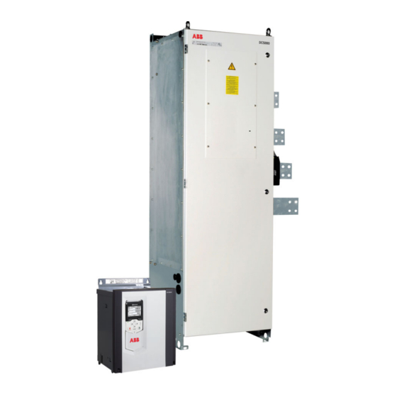
The DCS880 Chapter overview This chapter describes briefly the operating principle and construction of the converter modules in short. The DCS880 converter modules The DCS880-S size H1 ... H8 are intended for controlling DC motors. Size H1 ... H5 Size H6 20 ... -
Page 15: Type Code
Without control panel +J428 daisy-chain option DPI-H01 kit +J429 Bluetooth control panel ACS-AP-W The technical data and specifications are valid as of going to press. ABB reserves the right to make subsequent alterations. The DCS880 3ADW000462R0401 DCS880 Hardware manual e d... -
Page 16: Plus Codes
Plus codes Option Option code Description ACS-AP-I standard built-in no ACS-AP-I 0J404 No Control Panel ACS-AP-W +J429 Bluetooth panel DPI-H01 +J428 daisy-chain option FDNA-01 +K451 Fieldbus DeviceNet FPBA-01 +K454 Fieldbus PROFIBUS FCAN-01 +K457 Fieldbus CANOpen FSCA-01 +K458 Fieldbus Modbus FCNA-01 +K462 Fieldbus ControlNet FECA-01... -
Page 17: Main Circuit And Control
Main circuit and control Armature converter DCS880 H1 ... H4 400 V and 500 V (IEC) / 525 V (UL) units with OnBoard field exciter. 600 V units are always without OnBoard field exciter. DCS880-S0x as field exciter SDCS-DSL-H1x DCF803/804-0050/0060 DCF803-0035 DCF803-0016 max. -
Page 18: Armature Converter Dcs880 H5
Armature converter DCS880 H5 H5 units with optional internal field exciter. DCS880-S0x as field exciter SDCS-DSL-H1x DCF803/804-0050/0060 DCF803-0035 DCF803-0016 FEX-425-Int max. 500 V Slot1 Slot2 Slot3 X205 Slot1 Slot2 X200 The DCS880 3ADW000462R0401 DCS880 Hardware manual e d... -
Page 19: Armature Converter Dcs880 H6
Armature converter DCS880 H6 DCS880-S0x as field exciter SDCS-DSL-H1x DCF803/804-0050/0060 DCF803-0035 DCF803-0016 FEX-425-Int F3.1 (F301 - F303) Slot1 Slot2 Slot3 X205 Slot1 Slot2 X200 The DCS880 3ADW000462R0401 DCS880 Hardware manual e d... -
Page 20: Armature Converter Dcs880 H7 And H8
Armature converter DCS880 H7 and H8 DCS880-S0x as field exciter SDCS-DSL-H1x DCF803/804-0050/0060 DCF803-0035 DCF803-0016 Slot1 Slot2 Slot3 X205 Slot1 Slot2 X200 The DCS880 3ADW000462R0401 DCS880 Hardware manual e d... -
Page 21: Mechanical Installation
Mechanical installation Chapter overview This chapter describes the mechanical installation of the DCS880. Safety WARNING – DCS800 sizes H4 ... H8: – The drive is heavy. Lift the drive by lifting lugs only. – The drive’s center of gravity is high. Do not tilt the unit. The unit will overturn from a tilt of about 6 degrees. -
Page 22: Unpacking And Examining The Delivery (H1
Unpacking and examining the delivery (H1 … H3) This illustration shows the layout of the transport package. Examine that all items are present. Item Description Drive with factory installed options. Cardboard box. Shock damper. Shock dampers. Tray. Package containing documentation, plugs, mounting material, etc. BG_DCS_001_verpackung_a.ai Mechanical installation 3ADW000462R0401 DCS880 Hardware manual e d... -
Page 23: Unpacking And Examining The Delivery (H4)
Unpacking and examining the delivery (H4) This illustration shows the layout of the transport package. Examine that all items are present. Item Description Drive with factory installed options. Cardboard box. Shock damper. Shock dampers. Shock damper. Package containing documentation, plugs, mounting material, etc. BG_DCS_001_verpackung_a.ai Mechanical installation 3ADW000462R0401 DCS880 Hardware manual e d... -
Page 24: Unpacking And Examining The Delivery (H5)
Unpacking and examining the delivery (H5) This illustration shows the layout of the transport package. Examine that all items are present. Item Description Drive with factory installed options. Converter fan, remove before installation. Lifting lugs bracket. Lifting lugs bracket, attach before installation. Cardboard box. -
Page 25: Unpacking And Examining The Delivery (H6)
Unpacking and examining the delivery (H6) This illustration shows the layout of the transport package. Examine that all items are present. Item Description Drive with factory installed options. Cardboard box. Shock damper. Lower and upper cardboard box cover. Shock dampers. Package containing documentation, plugs, mounting material, etc. -
Page 26: Unpacking And Examining The Delivery (H7, H8)
Unpacking and examining the delivery (H7, H8) This illustration shows the layout of the transport package. Examine that all items are present. Item Description Drive with factory installed options. Cardboard box. Lower cardboard box cover. Brackets to fasten the drive, remove before installation. Shock damper. -
Page 27: Delivery Check
Delivery check Check that there are no signs of damage. Before attempting installation and operation, check the information on the nameplate of the converter module to verify that the unit is of the correct type. The label includes an IEC rating, cULus, C-tick (N713) and CE markings, a type code and a serial number, which allow individual identification of each unit. - Page 28 Ser. No. 0025421A17294264 1729 = Production year 2017 and week 29. Rated input voltage according to IEC. Rated output voltage according to IEC. Rated input voltage according to UL. Rated output voltage according to UL. Rated input current. Rated output current. Rated internal field exciter current.
-
Page 29: Installing The Drive (H1
Installing the drive (H1 … H3) This section tells you how to install the drive on wall without vibration dampers. The degree of protection is IEC: IP00 and UL: open type. 1. See the dimensions in chapter Dimensions and weights. Mark the locations for the four mounting holes. -
Page 30: Installing The Drive (H4, H5)
Installing the drive (H4, H5) This section tells you how to install the drive on wall without vibration dampers. The degree of protection is IEC: IP00 and UL: open type. 1. See the dimensions in chapter Dimensions and weights. Mark the locations for the four mounting holes. 2. -
Page 31: Installing The Drive (H6
Installing the drive (H6 … H8) Drives of sizes H6 … H8 are for cabinet mounting only. Cabinet installation The required distance between parallel units is five millimetres (0.2 in.) in installations without the front cover. The cooling air entering the unit must not exceed +40 °C (+104 °F). Preventing cooling air recirculation Unit above another Prevent air recirculation inside and outside the cabinet. -
Page 32: Terminal Options For Converter Modules Size H1
Terminal options for converter modules size H1 ... H4 There are different options to protect and connect the terminals. Connection of H4 converter module DC terminals In some cases it is beneficial to use lug bars for easy DC cable connection. DC terminals of of converter D4 module... - Page 33 The cable shield grounding plate is part of the accessort pack Example for DC main terminal cover for H4 converter modules. Mechanical installation 3ADW000462R0401 DCS880 Hardware manual e d...
-
Page 34: Mounting The Converter Module H5 Inside An Enclosure
Mounting the converter module H5 inside an enclosure Cooling air inlet Free space around the converter module The cooling fan blows the air out of the front, right and left side of the converter In mm: module. View from: Right side Front side Left side air flow... -
Page 35: Mounting The H7 Power Unit Inside An Enclosure
Mounting the H7 power unit inside an enclosure Cooling air inlet Free space around the converter module The cooling fan takes the air from the back, left, right side and from the bottom of Optimum Compromise the converter module. View from: Right side Back side Left side... -
Page 36: Mounting The H8 Power Unit Inside An Enclosure
Mounting the H8 power unit inside an enclosure Cooling air inlet Cable entries The cooling fan takes the air from the back, left, right The cable entries are symmetric on both sides. side and from the bottom of the converter module. Nevertheless only the entries on the left side should View from: be used for cables connected to the electronic power... -
Page 37: Planning The Electrical Installation
Always follow local regulations. This chapter applies to all DCS880 converter modules. Attention: If the recommendations given by ABB are not followed, the drive may experience problems not covered by warranty. See also Technical guide. - Page 38 Configuration C Line If a dedicated transformer / isolation transformer is used, it is possible to comply with certain connecting conditions per Configuration B without using an additional line reactor. The condition described in Configuration A will then likewise be satisfied, since the u is >...
- Page 39 Line reactors (L ) Selection Size DCS Type Line reaktor Design Line reaktor Design 400 V... 690 V = 1 %) Fig. = 4 %) Fig. 50 / 60 Hz 2-Q Converter 4-Q Converter DCS880-S01-0020-04/05 DCS880-S02-0025-04/05 ND01 ND401 DCS880-S01-0045-04/05 DCS880-S02-0050-04/05 ND02 ND402 DCS880-S01-0065-04/05...
-
Page 40: Semiconductor Fuses (F1)
Semiconductor fuses (F1) Aspects of fusing for the armature and field circuit of DC drives. Unit configuration Protection elements such as fuses or overcurrent trip circuits are required in all cases to protect against further damage. In some configurations, this will entail the following questions: 1. -
Page 41: Semiconductor Fuses (F1) And Fuse Holders For Armature Circuit
Conclusion for the field circuit Basically, similar conditions apply for both field and armature circuit. Depending on the converter used (half-controlled bridge, fully controlled bridge), some of the fault sources may not always be applicable. Due to special system conditions, such as supply via an autotransformer or an isolating transformer, new protection conditions may occur. -
Page 42: Fuses (F3.X) And Fuse Holders For Field Circuit
Size Converter type (2-Q) Converter type (4-Q) Fuse Fuse holder Fuse Fuse holder North America DCS880-S01-0020-04/05 DCS880-S02-0025-04/05 50A 660V UR OFAX 00 S3L FWP-50B 1BS101 DCS880-S01-0045-04/05 DCS880-S02-0050-04/05 80A 660V UR OFAX 00 S3L FWP-80B 1BS101 DCS880-S01-0065-04/05 DCS880-S02-0075-04/05 125A 660V UR OFAX 00 S3L FWP-125A 1BS103... -
Page 43: Single-Phase Autotransformer (T3) For Field Circuit (Adapt Voltage)
Single-phase autotransformer (T3) for field circuit (adapt voltage) The field converters insulation voltage is higher than its rated voltage (see chapter Accessories). This provides the possibility in systems with more than 500 V mains voltage to supply the field converter directly. -
Page 44: Line Reactors For Single- And 3-Phase Connection Of Field Converters
Line reactors for single- and 3-phase connection of field converters Field converters DCF803-0016, FEX-425-Int and DCF803-0035 need additional external line reactors. Field converters DCF803-0050, DCF804-0050, DCF803-0060 and DCF804-0060 do not need additional line reactors since they already have internal line reactors. Field converter type Field current Line reactor type... -
Page 45: Emc Filters (E1)
EMC filters are necessary to fulfil the standard for emitted interference if a converter shall be run at a public low voltage line, in Europe for example with 400 V . Such lines have a grounded neutral conductor. ABB offers suitable three-phase filters for 400 V . For 440 V public low voltage lines outside Europe 500 V filters are available. - Page 46 EMC filters Further information is The paragraphs below describe selection of the electri- • the product's actual emissions. available in the cal components in conformity with the EMC Guideline. The EMC Guideline expects EMC to be taken into Technical guide The aim of the EMC Guideline is, as the name implies, account when a product is being developed;...
- Page 47 ≤ 1.2 MVA) zone Product Standard with earthed EN 61800-3 Converter transformer For the DCS880 series, the Earthed iron core limit values for emitted neutral (and earthed Earthed 400 V network I > 400 A interference are complied screen where with neutral conductor ;...
-
Page 48: Converters Size H1
Converters size H1 ... H4 configuration using an OnBoard field exciter Wiring the drive according to this diagram offers the highest degree of monitoring functions done by the drive. DIOGND IACT +24VD AGND DICOM +24VD AGND Off2 (current off) AI3- AI3+ Fan acknowledge AI2-... -
Page 49: Converters Size H5 Configuration Using Fex-425-Int Field Exciter
Converters size H5 configuration using FEX-425-Int field exciter Wiring the drive according to this diagram offers the highest degree of monitoring functions done by the drive. Field converters FEX-425-Int are equipped with their own synchronization and must be supplied from independent mains supply voltage max. 500 V (single-phase or 3-phase). DIOGND IACT +24VD... -
Page 50: Converters Size H6 Configuration Using A Fex-425-Int Field Exciter
Converters size H6 configuration using a FEX-425-Int field exciter Wiring the drive according to this diagram offers the highest degree of monitoring functions done by the drive. Field converters FEX-425-Int are equipped with their own synchronization and must be supplied from independent mains supply voltage max. 500 V (single-phase or 3-phase). DIOGND IACT +24VD... -
Page 51: Converters Size H1
Converters size H1 ... H6 configuration using external field exciters DCF803, DCF804 Wiring the drive according to this diagram offers the highest degree of monitoring functions done by the drive. Field converters DCF803 / DCF804 are equipped with their own synchronization and must be supplied from independent mains supply voltage max. -
Page 52: Converters Size H7 And H8 Configuration Using External Field Exciters Dcf803, Dcf804
Converters size H7 and H8 configuration using external field exciters DCF803, DCF804 Wiring the drive according to this diagram offers the highest degree of monitoring functions done by the drive. Field converters DCF803 / DCF804 are equipped with their own synchronization and must be supplied from independent mains supply voltage max. -
Page 53: Converters Size H1
Converters size H1 ... H3 as large field exciter Wiring the drive according to this diagram offers the highest degree of monitoring functions done by the drive. DIOGND IACT +24VD AGND DICOM +24VD AGND Off2 (current off) AI3- AI3+ Overvoltage protection trigger AI2- AI2+... -
Page 54: Start, Stop And E-Stop Control
Start, Stop and E-Stop control The relay logic is splitted into four parts: 1: Generation of the On / Off and Start / Stop commands: The commands represented by K20 and K21 (latching interface relays) can also be generated by a PLC and transferred to the terminals of the converter either by relays, using galvanic isolation or directly via 24 V signals. - Page 55 Emergency stop Speed Off3 Off2 Timer relay (K15) Timer relay (K16) Block current control Off2 (current off) Mains contactor (K1) Off2 Emergency stop ramp Coast DZ_LIN_006_E-stop_b.ai Emergency stop reaction XD24 +24 VD SF_CON4_001_E-stop_b.ai 4:DC contactor (US style): The DC contactor (US style) K1.1 is a special designed DC contactor with one normally closed contact for the dynamic braking resistor R and two normally open contacts for C1 and D1.
-
Page 56: Cooling Fans
Cooling fans Fan assignment for DCS880 Converter type Size Configuration Fan type Airflow built in [m³/h] DCS880-S0b-0045-04/05 ... 1 x 3110UL DCS880-S0b-00100-04/05 DCS880-S0b-0135-04/05 ... 2 x AFB122 DCS880-S0b-0300-04/05 DCS880-S01-0290-06 DCS880-S02-0320-06 DCS880-S0b-0315-04/05 ... DCS880-S0b-0450-04/05 DCS880-S0b-0470-04/05 ... 2 x 3110UL DCS880-S0b-0520-04/05 2 x AFB122 DCS880-S01-0590-06 1 x W2E200 ... -
Page 57: Fan Connection For Dcs880 (H1
Fan Data for DCS880 (H1 ... H4) 3110UL AFB122 W2E200 W2E250 24 V internal 24 V internal Rated voltage [V 230; 1~ 230; 1~ Tolerance [%] +6 / -10 +6 / -10 Frequency [Hz] Power consumption [W] Current consumption [A] 0.29 0.35 0.59... -
Page 58: Fan Connection For Dcs880 (H5
Fan data for DCS880 (H5 ... H8) R2E250-RB GR28C-2DK GR35C-2DD 400 460 Rated voltage [V 230; 1~ 400 / 460 460 / 500 V 500 V Tolerance [%] ±10 ±10 ±10 ±10 Frequency [Hz] 660 1100 ... -
Page 59: Monitoring The Dcs880 Power Section
The protective characteristics of circuit breakers depend on their type, construction and settings. There are also limitations regarding to the short-circuit capacity of the supply network. Your local ABB representative can help you in selecting the breaker type when the supply network characteristics are known. - Page 60 Protecting the drive and the input power and motor cables against thermal overload The drive protects itself, its mains- and the motor cables against thermal overload when the cables are sized according to the nominal current of the drive. No additional thermal protection devices are needed. WARNING If the drive is connected to multiple motors, use a separate circuit breaker or fuses for protecting each motor cable and motor against overload.
-
Page 61: Cross-Sectional Areas - Tightening Torques
Cross-sectional areas - Tightening torques Recommended cross-sectional area to DINVDE 0276-1000 and DINVDE 0100-540 (PE) trefoil arrangement, up to 50°C ambient temperature. The necessary wire torque at 60°C wire temperature is the same as recommended in the following table. Armature: Converter type C1, D1 U1, V1, W1... -
Page 62: Selecting The Power Cables
Selecting the power cables General rules – Select the input power and motor cables according to local regulations. – Select a cable capable of carrying the drive nominal current. See chapter Current ratings. ° – Select a cable rated for at least 60 C maximum permissible temperature of conductor in continuous use. - Page 63 Relay cable type The cable type with braided metallic screen (for example ÖLFLEX by LAPPKABEL, Germany) has been tested and approved by ABB. Control Panel cable length and type In remote use, the cable connecting the control panel to the drive must not exceed three meters (10 ft).
-
Page 64: Connection Of A Motor Temperature Sensor To The Drive I/O
Connection of a motor temperature sensor to the drive I/O WARNING IEC 60664 requires double or reinforced insulation between live parts and the surface of accessible parts of electrical equipment which are either nonconductive or conductive but not connected to the protective earth. To fulfill this requirement, the connection of a thermistor (or other similar components) to the inputs of the drive can be implemented by 3 alternate ways: - There is double or reinforced insulation between the thermistor and live parts of... -
Page 65: Electrical Installation
Electrical installation Chapter overview This chapter describes the electrical installation procedure of the DCS880. WARNING A qualified electrician may only carry out the work described in this chapter. Follow the Safety instructions on the first pages of this manual. Ignoring the safety instructions can cause injury or death. -
Page 66: It (Ungrounded) Systems
IT (ungrounded) systems Don’t use EMC filters in IT systems. The screen winding of existing dedicated transformers must be grounded. For installation without low voltage switch (e.g. contactor, air-circuit-breaker) use an overvoltage protection on the secondary side of the mains transformer. The voltage shift of the isolated supply must not be larger than the voltage shift in case on an earth fault. -
Page 67: Location F-Type Adapters And Interfaces
Location F-type adapters and interfaces Connect the signal cables as described below. Tighten the screws to secure the extension modules and the memory unit. X13: Slot1: Control panel For all F-type extension modules control panel interface SDCS- X205: DPI-H01 Memory unit Slot2: For all F-type extension modules (recommended... -
Page 68: Fea-03 I/O Extension Adapter Configuration
FEA-03 I/O extension adapter configuration FEA-03 FEA-03 FEA-03 FEA-03 V1T V1R V1R V1T FDCO FDCO Drive Drive BG_880_003_FEA_c.ai Item Description Module connector 1 Status LED for Slot 1 Slot 1 Node address switch A (digit 10) Node address switch B (digit 0) Module connector 2 Status LED for Slot 2 Node address switch C (digit 10) -
Page 69: Pulse Encoder Connection
Pulse encoder connection OnBoard encoder interface (XENC on SDCS-CON-H01) On the SDCS-CON-H01 it is possible to select the supply voltage using jumper J4D. Hardware configuration Encoder supply SDCS-CON-H01 5 V, default no sense 24 V no sense The wiring is shown in the figure below. Commissioning hint: If the drive’s measured direction of rotation is wrong or = twisted... -
Page 70: Pulse Encoder Connection Principles
Pulse encoder connection principles Two different encoder connections are available. 1. Differential connection; only pulse encoders generating voltage signals can be used. 2. Single-ended (push pull) connection; only pulse encoders generating voltage signals can be used. Pulse encoder connection principles: Single ended Single ended push pull... - Page 71 Jumper settings for differential encoders connected to Differential +5V or +24V XENC:8 SDCS-CON-H01 XENC:1 Jumper SDCS-CON-H01 1 - 2 1 - 2 Differential 4 - 5 4 - 5 100 nF 7 - 8 7 - 8 XENC:2 SDCS-CON-H01 ENCODER INPUT A XENC:7 5 V: 24 V:...
-
Page 72: Connecting The Signal And Control Cables
Connecting the signal and control cables Used screened cables for digital signals, which are longer than 3 m and for all analog signals. Connect each screen at both ends by metal clamps or comparable means directly on clean metal surfaces, if both earthing points belong to the same earth line. Otherwise, connect a capacitor to earth on one end. -
Page 73: Dcslink Wiring
Continuous motor cable shield or enclosure for equipment on the motor cable To minimize the emission level when safety switches, contactors, connection boxes or similar equipment are installed on the motor cable between the drive and the motor: – European Union: Install the equipment in a metal enclosure with 360 degree grounding for the shields of both the incoming and outgoing cable, or connect the shields of the cables otherwise together. - Page 74 Example of two DCS880 converters, one as armature converter, the other one as large field exciter. DCS880 Converter DCS880 Converter as large field exciter SDCS-DSL-H1x SDCS-DSL-H1x GNDB GNDB X52: 1 2 3 3 2 1 X53: X52: 1 2 3 3 2 1 X53: Bus termination (J1:...
- Page 75 Example of one DCS880 converter plus external field supply. DCS880 Converter SDCS-DSL-H1x X1:1 +24 V DCF803-0035 X1:2 X51:1 +24 V X51:2 S1100:2 GNDB GNDB S1100:1 S1100:3 1 2 3 3 2 1 X53: X3: 2 X52: Ground termination (S1100:2 open S1100:3 open) Bus termination (S1100:1 closed)
-
Page 76: Connecting A Control Unit At H7 And H8 Power Units
Connecting a control unit at H7 and H8 power units During installation the control unit needs to be connected with the power unit using fiber optic cables. For a standard drive connect the fiber optic cables from the SDCS-DSL-H1x (control unit) to the SDCS-OPL-H01(power unit). -
Page 77: Installation Checklist
Installation checklist Check the mechanical and electrical installation of the drive before start-up. Go through the checklist below together with another person. Read the Safety instructions on the first pages of this manual before you work on the unit. MECHANICAL INSTALLATION The ambient operating conditions are allowed (see Environmental Conditions, Current ratings) The unit is mounted properly on a vertical non-flammable wall (see... -
Page 78: Maintenance
Maintenance Chapter overview This chapter contains preventive maintenance instructions. For more information see DCS880 Service Manual. Safety WARNING Read the Safety instructions on the first pages of this manual before performing any maintenance on the equipment. Ignoring the safety instructions can cause injury or death. Maintenance 3ADW000462R0401 DCS880 Hardware manual e d... -
Page 79: Technical Data
Technical data Chapter overview The technical data contain the technical specifications of the converter, e.g. the ratings, sizes and technical requirements, provisions for fulfilling the requirements for CE and other markings and warranty policy. Environmental Conditions System connections Environmental limit values Voltage, 3-phase: 100 ... - Page 80 The converter module and enclosed converter components are designed for use in industrial environments. In EEA countries, the components fulfil the requirements of the EU directives, see table below: European Union Directive Manufacturer's Assurance Harmonized Standards Converter module Machinery Directive 2006/42/EC Declaration of Incorporation [IEC 60204-1]...
-
Page 81: Current Ratings - Iec Regenerative Converters (S02)
Current ratings - IEC regenerative converters (S02) See the current ratings including several standard duty cycles for the DCS880 with 50 Hz and 60 Hz supplies below. The current ratings are based on an ambient temperature of maximum 40°C and an elevation of maximum 1000 m above mean sea level: Size Internal field current... -
Page 82: Current Ratings - Iec Non Regenerative Converters (S01)
Current ratings - IEC non regenerative converters (S01) Internal Size Unit type DC I DC II DC III DC IV field current 100 % 150 % 100 % 150 % 100 % 200 % continuous 2-Q converters 15 min 60 s 15 min 120 s 15 min... -
Page 83: Control Board Sdcs-Con-H01 (H1
Control board SDCS-CON-H01 (H1 ... H8) The control circuit terminals are common for all sizes H1 … H8. Location of the control circuit board SDCS-CON-H01 The SDCS-CON-H01 is mounted on an electronic tray. The electronic tray is attached in the housing by means of two hinges. -
Page 84: Intermediate Cover
Intermediate cover Technical data 3ADW000462R0401 DCS880 Hardware manual e d... -
Page 85: Control Circuit Terminal Layout
Control circuit terminal layout Internal 24 V used External 24 V used DCS880 Reference voltage and analog inputs +VREF +10 V -VREF -10 V AGND Common ground (connected to frame) AI1+ ±10 V or 0 (4) ... 20 mA depending on J1 AI1- AI2+ ±10 V or 0 (4) ... -
Page 86: Xai: Reference Voltages And Analog Inputs
XAI: Reference voltages and analog inputs +VREF +10 V , ±1 % = 1 … 10 k Maximum wire size 2.5 mm -VREF -10 V , ±1 % = 1 … 10 k Maximum wire size 2.5 mm = 100 ] depending on J1 AI1+ ±10 V [R ≥... -
Page 87: Ro1, Ro2, Ro3: Relay Outputs
Set the termination switch J3 (see Jumpers and switches) next to terminal block XD2D to terminated ( ) at the two physical ends of the drive-to-drive link. All intermediate switches have to be set to not terminated Use double shielded twisted-pair cable ( 100 , for example, PROFIBUS compatible cable) for the wiring. For best immunity, high quality cable is recommended. -
Page 88: Xdio: Digital Inputs / Outputs
XDIO: Digital inputs / outputs DIO1 Maximum wire size 2.5 mm As input: DIO2 +24 V logic levels: low < 5 V , high > 15 V = 2 k Filter: 0.25 ms As output: Total output current from +24VD is limited to 200 mA Filter: 0.04 ms Related ground is DIOGND Parameter settings see... -
Page 89: Xsmc: Mains Contactor
XSMC: Mains contactor MCCOM Fixed output for the mains contactor 250 V / 30 V , 2 A MCNO Maximum wire size 2.5 mm Varistor protected STOCOM Fixed output for safe torque off (STO) zero current monitor 250 V / 30 V , 2 A STONO Maximum wire size 2.5 mm... -
Page 90: Replacing The Memory Unit
Replacing the memory unit Make sure, that the auxiliary power is off. Unscrew the memory unit and pull it out. Replace the memory unit in reverse order. Additional terminals – Use connectors Slot1 … Slot3 for F-type I/O extension modules and F-type fieldbus adapters. –... -
Page 91: Ground Isolation Diagram
Ground isolation diagram +VREF -VREF AGND AI1+ AI1- Common mode voltage AI2+ between channels ± 30 V AI2- AI3+ AI3- AGND AGND IACT XD2D Isolation BGND Switch J6 settings: XRO1, XRO2, XRO3 The ground (DICOM) of digital inputs DI1 … DI5 and DIL is separated from the ground (DIOGND) of digital inputs / outputs Open DIO1, DIO2 and DI6. -
Page 92: Jumpers And Switches
Jumpers and switches Jumper / Switch Description Positions J1 (AI1) Determines whether analog input AI1 is used as a current Current (I) or voltage input. Voltage (U), default. J2 (AI2) Determines whether analog input AI2 is used as a current Current (I) or voltage input. -
Page 93: Ddcs Interface Configuration
DDCS Interface configuration Ch0 DriveBus or module bus connection to Advant Controller (star) FDCO-0x FDCO-0x FDCO-0x . . . 30 m Plastic POF 200 m HCS . . . 0, 1, 2 ..8 NDBU-95 30 m Plastic POF 200 m HCS AC 800M:CI 858 DriveBus module PEC800:CI 858 DriveBus module FCI:CI 810 Adapter module... -
Page 94: Ddcs Branching Unit Ndbu-95
DDCS branching unit NDBU-95 The NDBU-95 is used to implement star topology for DDCS communication. This allows a drive to fail or become unpowered without disabling the complete communication. The NDBU-95 receives messages from the master (e.g. PC) and sends them to all the drives simultaneously. Each drive has an individual address and only the addressed drive sends a reply message to the master. -
Page 95: Dcslink Board Sdcs-Dsl-H1X (H1
DCSLink board SDCS-DSL-H1x (H1 ... H8) The SDCS-DSL-H1x provides communication between drives. The communication hardware and protocol is based on CAN bus. This communication will be used for drive-to-drive communication, 12-pulse operation and communication to field exciters. The communication hardware is equipped with an isolated power supply and an isolated transmitter. The bus termination can be set by jumper J1. -
Page 96: Daisy Chain Dpi-H01 Kit (H1
Daisy chain DPI-H01 kit (H1 ... H8) Daisy chain adapters are used to connect several drives to one control panel or to a PC via a control panel. Maximum of 32 nodes are possible. The control panel / PC is the master, while the drives equipped with a daisy chain adapter are followers. - Page 97 Installation 1. Inset the four stand offs into the intermediate cover. 2. Connect the patch cable between X13 on the SDCS-CON-H01 and X13 on the SDCS-DPI-H01 adapter. 3. Plug the SDCS-DPI-H01 adapter onto the standoffs. 4. Connect the grounding cable at X1 and the ground- ing standoff using the screw.
- Page 98 Chaining a PC via a control panel This figure shows how to chain a PC via a control panel to several drives. Note: When a control panel is used for a PC connection, it cannot be used to operate the drives. …...
-
Page 99: Power Interface Board Sdcs-Pin-H01 (H1
Power Interface board SDCS-PIN-H01 (H1 ... H5) The SDCS-PIN-H01 is designed for DCS880 converter modules sizes H1 ... H5 (20 A ... 1190 A). It has 4 different functions: 1. The power supply for all internal voltages of the whole drive and the connected options (H1 ... H5). 2. -
Page 100: Technical Data
Technical data Auxiliary supply voltage XAUX (X99) Auxiliary voltage 115 V 230 V 230 V Tolerance -15 % / +10 % -15 % / +10 % -15 % / +10 % Frequency 45 Hz ... 65 Hz 45 Hz ... 65 Hz Power consumption 120 VA 120 VA... -
Page 101: Power Supply Board Sdcs-Pow-H01 (H6
Power supply board SDCS-POW-H01 (H6 ... H8) The SDCS-POW-H01 is designed for DCS880 converter modules and is mounted on the electronic tray. It is used for sizes H6, H7, H8 and the rebuild kit DCS880-R. The SDCS-POW-H01 generates all necessary DC voltages for the SDCS-CON-H01 and all other electronic boards. -
Page 102: Field Circuit Interfaces Sdcs-Bab-F01 And Sdcs-Bab-F02 (H1
Field circuit interfaces SDCS-BAB-F01 and SDCS-BAB-F02 (H1 ... H4) The OnBoard field exciter is located internally. The firing pulses are synchronized using the mains circuit L1, L2, L3 and the SDCS-CON-H01. The pulses are amplified on the SDCS-PIN-H01. The hardware structure is a three phase half controlled bridge supplied directly from the mains U1, V1, W1 via fuses F100, F101, F102. - Page 103 Layout SDCS-BAB-F01 for module sizes H1 and H2: SF_BABF_001_a.ai T100 SDCS-BAB-F02 for module sizes H3 and H4: SF_BABF_001_a.ai X10 : F- T100 X10 : F+ Location The SDCS-BAB-F0x is located between the power part and the control board SDCS-CON-H01. Functions The SDCS-BAB-F0x is a three-phase half-controlled field exciter.
- Page 104 Circuit diagram Typical armature circuit diagram for module sizes H1 and H2 using SDCS-PIN-H01 and SDCS-BAB-F01: Technical data 3ADW000462R0401 DCS880 Hardware manual e d...
- Page 105 Typical armature circuit diagram for module sizes H3 and H4 using SDCS-PIN-H01 and SDCS-BAB-F02: Technical data 3ADW000462R0401 DCS880 Hardware manual e d...
- Page 106 Typical armature circuit diagram for module size H5 using SDCS-PIN-H01: Technical data 3ADW000462R0401 DCS880 Hardware manual e d...
-
Page 107: Measuring Board Sdcs-Pin-H51 (H6
Measuring board SDCS-PIN-H51 (H6 ... H8) The measuring board is equipped with inputs for current measurement via CTs, high ohmic voltage measurement and an input for a temperature sensor. Following connectors are available: 1. Four identical channels for current measurement on the mains side via CTs connected to X231 / X232, X241 / X242, X251 / X252 and X261 / X262. - Page 108 Switches Leave switch J1 on separated (default). Location of the SDCS-CON-H01 Size H6: - The board is located inside the module. Module sizes H7 and H8 consist of a control unit and a power unit: - The board is located inside the power unit. Layout of the SDCS-PIN-H51 V111 R121...
-
Page 109: Firing Pulse Transformer Board Sdcs-Pin-H41 (H6
Firing pulse transformer board SDCS-PIN-H41 (H6 ... H8) The interface to the power part of the converter modules size H6 ... H8 from 900 A up to 5200 A consists of one or two firing pulse transformer boards SCDS-PIN-H41. Single bridge converters (2-Q) are equipped with one board. Converters with 2 anti-parallel bridges (4-Q) require two boards. -
Page 110: Optical Power Link Board Sdcs-Opl-H01 (H7, H8)
Optical power link board SDCS-OPL-H01 (H7, H8) Module sizes H7 and H8 consist of a control unit and a power unit. The board provides the interface between control unit and power unit using fiber optic cables. Following connectors are available Fiber optic connectors V1, V2 connect the SDCS-CON-H01 via SDCS-DSL-H1x for control. -
Page 111: Location Of The Sdcs-Opl-H01
Location of the SDCS-OPL-H01 The board is located inside the power unit. Layout of the SDCS-OPL-H01 X300 X350 STO in STO out Control Current measurement using a scope XSMC (X96) BL_OPL-H01_001_b.ai Mains IACT contactor Current measurement Mains contactor via scope Technical data 3ADW000462R0401 DCS880 Hardware manual e d... -
Page 112: Connection Between Firing And Control Board For H6
Connection between firing and control board for H6 ... H8 2-Q, size H6 SDCS-PIN-H41 SDCS-PIN-H51 BL_PIN-H41_001_2Q_c .ai 4-Q, size H6 SDCS-PIN-H51 SDCS-PIN-H41 SDCS-PIN-H41 BL_PIN-H41_002_4Q_c.ai 2-Q, sizes H7 and H8 SDCS-PIN-H41 SDCS-PIN-H51 SDCS-DSL-H1x SDCS-CON-H01 SDCS-OPL-H01 Control unit Power unit BL_PIN-H41_001_2Q_c .ai 4-Q, sizes H7 and H8 SDCS-PIN-H51 SDCS-DSL-H1x... - Page 113 Circuit diagram Typical armature circuit diagram for module size H6 with SDCS-PIN-H51 and SDCS-PIN-H41: XS23: 6,12,17 4,10 n.c. 19,20 Technical data 3ADW000462R0401 DCS880 Hardware manual e d...
- Page 114 Typical armature circuit diagram for module sizes H7 and H8 with SDCS-PIN-H51 and SDCS-PIN-H41: XS23: 6,12,17 4,10 n.c. 19,20 Technical data 3ADW000462R0401 DCS880 Hardware manual e d...
-
Page 115: Galvanic Isolation - T90, A92, F11, F90
Galvanic isolation - T90, A92, F11, F90 The Galvanic isolation is an option for DC-DC transducer A92 Transformer T90 SDCS-PIN-H51 converters size H6 ... H8 and rated voltages 1000 V. For converters with a rated AC voltage of > 1000 V or 12-pulse serial >... - Page 116 Typical armature circuit diagram for module sizes H6 ... H8 with SDCS-PIN-H51, SDCS-PIN-H41 and galvanic isolation: XS23: 6,12,17 4,10 n.c. 19,20 Technical data 3ADW000462R0401 DCS880 Hardware manual e d...
-
Page 117: Dc-Dc Transducer A92 (1)
DC-DC transducer A92 (1) Principle circuit diagram of the DC-DC transducer A92 (1) 10 pF 1 nF Z 15 V Voltage input Output U/I SF_WAN_001_A92_a.ai Power supply 20 - 253 V AC/DC Data Selectable voltage gains 1080 1350 1620 Switch position Output voltage: 20 mA;... -
Page 118: Transformer T90
Transformer T90 Principle diagram of the transformer T90 (3ADT745047) Data Selectable transfer ratios U 500, 600, 690, 800,1000, 1200 V prim Output voltage: 7.3 V Insulation voltage: 1200 V Isolation test voltage: 3500 V Ambient temperature range: - 10 ... + 70 °C Weight: 2.1 kg Dimensions in mm... -
Page 119: Dimensions And Weights
Dimensions and weights See the dimensional drawings of the DCS880 below. The dimensions are in millimeters. Size h * w * d [mm] h * w * d [inch] weight [kg] weight [lbs] 370*270*215 14.56*10.63*8.46 370*270*271 14.56*10.63*10.67 460*270*317 18.11*10.63*12.48 645*270*352 25.39*10.63*13.86 750*270*372 29.53*10.63*14.65... -
Page 120: Size H2
Size H2 DCS880-S01-0135 DCS880-S01-0180 DCS880-S01-0225 DCS880-S01-0270 DCS880-S02-0150 DCS880-S02-0200 DCS880-S02-0250 DCS880-S02-0300 min. min. Air flow Field terminals Field terminals Screw M6 Signal terminals Aux. supply terminals Power terminals 121.5 112.5 164.5 (PIN-H01) Earthing M8 228 (CON-H01) Screw M10 25 Nm 4 x 45 = 180 MG_880_002_H2_b.ai Dimensions and weights 3ADW000462R0401 DCS880 Hardware manual e d... -
Page 121: Size H3
Size H3 DCS880-S01-0315 DCS880-S01-0405 DCS880-S01-0470 DCS880-S02-0350 DCS880-S02-0450 DCS880-S02-0520 600 V Units DCS880-S01-0290 DCS880-S02-0320 Air flow min. min. Field terminals Field terminals Screw M6 Signal terminals Aux. supply terminals Power terminals 147.5 208 (PIN-H01) 272 (CON-H01) Screw M10 Earthing M10 4 x 45 = 180 MG_880_003_H3_b.ai Dimensions and weights 3ADW000462R0401 DCS880 Hardware manual e d... -
Page 122: Size H4
Size H4 DCS880-S01-0610 DCS880-S01-0740 DCS880-S01-0900 DCS880-S02-0680 DCS880-S02-0820 DCS880-S02-1000 600 V Units DCS880-S01-0590 DCS880-S02-0650 min. min. Air flow Field terminals Field terminals Fan terminals Screw M6 Signal terminals Aux. supply terminals Power terminals 147.5 Screw M12 195.5 243 (PIN-H01) 32.5 Earthing M12 305 (CON-H01) MG_880_004_H4_a.ai Dimensions and weights... -
Page 123: Size H5
Size H5 DCS880-S01-1190 DCS880-S02-1190 min. min. Fan terminal Screw M6 Air flow Aux. supply terminals Signal terminals Power terminals Screw M12 17.5 290 (PIN-H01) 307 (CON-H01) * Earthing M12 MG_880_005_H5_b.ai Dimensions and weights 3ADW000462R0401 DCS880 Hardware manual e d... -
Page 124: Size H6
Size H6 DCS880-S0B-0900 Busbars in mm: DCS880-S0B-1200 DC: 80 x 10 DCS880-S0B-1500 AC: 60 x 5 DCS880-S0B-2000 85.5 17 For M10 127.5 Support Support > 510 min.480 Earthing M12 Cable tray width = 40 mm Earthing M12 height = 39 mm Fan terminal 349.5 65.5 25 50 50... -
Page 125: Size H7
Size H7 (+P906) DCS880-S0b-1900 DCS880-S0b-2050 DCS880-S0b-2500 DCS880-S0b-3000 458,2 With external control unit (+P906) Air outlet 10x20 SDCS-OPL-H01 Ear thing M10 For M6 Air entry MG_880_008_H7_a.ai 10x20 From the front, right, left and back 468,2 Earthing M6 MG_880_007_Control unit_a.ai Power unit Control unit Dimensions and weights 3ADW000462R0401 DCS880 Hardware manual e d... -
Page 126: Size H8 Lefthand (+P906)
Size H8 lefthand (+P906) DCS880-S0b-4800-0dL DCS880-S0b-5200-0dL For M10 With external control unit (+P906) DCS880 Pressure switch Earthing M12 For M10 For M6 MG_800_007_D7_a.ai Busbars in mm: AC and DC: 100 x 10 Earthing M6 MG_880_007_Control unit_a.ai Control unit Power unit Dimensions and weights 3ADW000462R0401 DCS880 Hardware manual e d... -
Page 127: Size H8 Righthand (+P906)
Size H8 righthand (+P906) DCS880-S0b-4800-0dR DCS880-S0b-5200-0dR With external control unit For M10 (+P906) DCS880 Pressure switch Earthing M12 For M10 For M6 MG_800_007_D7_b.ai Busbars in mm: AC and DC: 100 x 10 Earthing M6 MG_880_007_Control unit_a.ai Power unit Control unit Dimensions and weights 3ADW000462R0401 DCS880 Hardware manual e d... -
Page 128: Branch Fuses Installed Inside Converter Sizes H5
Branch fuses installed inside converter sizes H5 ... H8 Size Converter type Fuse type Fuse Size 400 V / 500 V (IEC) / 525 V (UL) C1 (+) DCS880-S0b-1190-04/05 UR 900 A / 690 V DCS880-S0b-1200-04/05 UR 800 A / 660 V Branching fuse DCS880-S0b-1500-04/05 UR 1250 A / 660 V... - Page 129 Size 2 Size A [mm] B [mm] D [mm] E [mm] G [mm] Size 5, 6 Size 7 ... 9 Indicator max 105 4xM10 min 10 deep max d Ø 11 Size A [mm] Size a [mm] b [mm] c [mm] d [mm] Note: The given dimensions may be exceeded in some cases.
-
Page 130: Dcf803-0016, Fex-425-Int And Dcf803-0035
Accessories DCF803-0016, FEX-425-Int and DCF803-0035 The field exciters DCF803-0016, FEX-425-Int and DCF803-0035 are half controlled 3-phase converters. All field excitiers are based on the same control board SDCS-FEX-4. The board is equipped with its own synchronization and current control. The current measurement circuit is automatically scaled depending on the rated field current of the motor. -
Page 131: Electrical Data
Electrical data Power part AC input voltage 110 V -15% ... 500 V +10%; single or 3-phase AC input current < DC output current Frequency Same as DCS converter AC isolation voltage 600 V Line reactor External Line fuses KTK25 for FEX-425-Int; external for DCF803-0016 and DCF803-0035 ... -
Page 132: Dcslink Communication
Voltage ripple of voltage U depending on operation modes. Single-phase, half-controlled 0.75 0.25 3-phase, half-controlled 3-phase, full-controlled Field DZ_LIN_014_Spg-well_a.ai DCSLink communication The field converter is controlled from armature converter via DCSLink based on CAN hardware. SDCS-FEX-4 Incoming power Remarks X1:1 200 mA 24 V / 200 mA 24 V... -
Page 133: Rs232-Port
RS232-Port The RS232 interface is used for download the 'Field exciter firmware package'. The firmware download is activated by setting S2:1-2 before the auxiliary voltage is switched ON. Field exciter mode is S2:3-4 (default). Diagnostics All messages are sent to the armature converter and displayed in Signals 04.26, 04.27, 04.36 and 04.37. -
Page 134: Dcf803-0016 And Dcf803-0035 Configuration (H1
DCF803-0016 and DCF803-0035 configuration (H1 ... H8) 3-phase connection, see also parameters 28.63 and 42.68. DCF803-0016 / 35 F3.1 D1 (-) SDCS-FEX-4 5 A (+) 16 / 35 A (+) Supply voltage max. 500 V SF_DCF_003_FEX4_a.ai Single-phase connection, see also parameters 28.63 and 42.68. F3.2 DCF803-0016 / 35 F3.1... -
Page 135: Dimensions
Dimensions DCF803-0016 Dimensions in mm 36.5 Weight appr. 6 kg S1100 For mounting on mounting plate provide hole with diameter of min 5 mm for thermal sensor 16A 5A D1 U1 V1 W1 Earthing M6 Terminal X100, X101 cross-section max. AWG 7 MG_DCF_002_803-0016_a.ai DCF803-0035 Dimensions in mm... -
Page 136: Fex-425-Int Configuration (H5)
FEX-425-Int configuration (H5) 3-phase connection, see also parameters 28.63 and 42.68. F3.1 X101: FEX-425-Int X100: F301 D1(-) SDCS-FEX-4 F302 5A(+) F303 35A(+) Supply voltage max. 500 V SS_FEX4_001_config_b.ai Single-phase connection, see also parameters 28.63 and 42.68. F3.1 X101: FEX-425-Int X100: F3.2 F301 D1(-) -
Page 137: Fex-425-Int Configuration (H6)
FEX-425-Int configuration (H6) 3-phase connection, see also parameters 28.63 and 42.68. F3.1 FEX-425-Int F301 D1(-) Plus code +S164 SDCS-FEX-4 F302 5A(+) F303 35A(+) Supply voltage max. 500 V SS_FEX4_001_config_b.ai Single-phase connection, see also parameters 28.63 and 42.68. F3.1 FEX-425-Int F3.2 F301 D1(-) Plus code +S164... -
Page 138: Dcf803-0050, Dcf804-0050, Dcf803-0060 And Dcf804-0060
DCF803-0050, DCF804-0050, DCF803-0060 and DCF804-0060 DCF803-0050 / 0060 and DCF804-0050 / 0060 are external single-phase field converters. The half controlled (1-Q) field exciters DCF803-0050 / DCF803-0060 include the SDCS-FEX-82, two thyristor/diode power modules and auxiliaries (power supply, line reactor L1). The full controlled (4-Q) field exciters DCF804-0050 / DCF804-0060 include the SDCS-FEX-81, four anti-parallel thyristor power modules and auxiliaries (power supply, line reactor L1). -
Page 139: Electrical Data
Electrical data Power part AC input voltage 110 V -15 % ... 500 V +10 %; single-phase AC input current < DC output current Frequency Same as DCS module AC isolation voltage 690 V 160 H; 45 ... 65 Hz (built in) Line reactor (L1) ... -
Page 140: Control Unit
Control unit The control unit includes the following main blocks: – Micro controller H8 for control and firing. – Actual DC current measurement using an AC current transformer. – High ohmic measurement of AC and DC voltage. Residual resistance to ground =3.5 M(DCF803 =1.9 M(DCF804) –... -
Page 141: Dcslink Communication
DCSLink communication The field converter is controlled from armature converter via DCSLink based on CAN hardware. SDCS-FEX-81 / 82 DSL communication Remarks X2:3 S1100:1 CANL Bus termination S1100: 1 = ON 120 Ohm CANH 1 = OFF no termination GNDB Ground termination S1100:2 S1100:3... -
Page 142: Diagnostics
Diagnostics All messages are sent to the armature converter and displayed in Signals 04.26, 04.27, 04.36 and 04.37. If the communication is broken or node numbers are mixed up the simple fault display on the SDCS-FEX-81 / 82 can be used. Therefore the unit is equipped with two small LEDs. -
Page 143: Dcf803-0050 / 0060 And Dcf804-0050 / 0060 Configuration (E.g. 2 Motors)
DCF803-0050 / 0060 and DCF804-0050 / 0060 configuration (e.g. 2 motors) The data exchange between SDCS-CON-H01 and DCF803-0050 / 0060 or DCF804-0050 / 0060 via serial communication is configured as a bus. This link is used to transfer references, actual values and settings for up to two field exciters. - Page 144 Connection example The DCSLink communication is activated by S1100:8 = ON. The bus setting is made using S1100. The node numbers are set using S800 and S801. Procedure to change the node number: – Switch off the electronics supply voltage. –...
- Page 145 DCF803-0050 / DCF804-0050 X3: 2 1 X71: SDCS-FEX-81 Parts not mounted at DCF803-0050 SDCS-FEX-82 V12 / V14 are diodes at DCF803-0050 FORWARD REVERSE CANL CANH GNDB S1100:2 Termination 200 kOhm SF_DCF_001_50A-60A_b.ai C1(+) DCF803-0060 / DCF804-0060 X4: 1 2 x 115 V X3: 2 1 series connection...
-
Page 146: Dimensions
Dimensions DCF803-0050 DCF804-0050 Direction of air flow Dimensions in mm Weight appr. 11 kg all for M6 all for M6 C1 (+) D1 (-) S1100 Signal terminals DCSLink S801 (aux. voltages) S800 V731 V730 Aux. power supply terminals X3 Sub-D all for M6 all for M6 MG_DCF_001_50A-60A_b.ai... -
Page 147: Dcf505 / Dcf506 Overvoltage Protection
DCF505 / DCF506 Overvoltage Protection Certain converter modules sizes H1 ... H4 can be used as motor field supply. This operation needs separate active overvoltage protection DCF505 or DCF506. They protect the power part against inadmissibly high voltages. The overvoltage protection activates a free-wheeling circuit between connectors F+ and F- if an overvoltage occurs. The DCF505 / 506 consists of a trigger unit (SDCS-FEP-x) and a free-wheeling thyristor (two anti-parallel thyristors in a DCF506). - Page 148 Inductive load supply for other Overvoltage Protection applications 4-Q, 400 V / 500 V (IEC) / 525 V (UL) DCS880-S0b-1200-04/05 DCF506-1200-51 1 x 25 1 x M8 DCS880-S0b-1500-04/05 4-Q, 690 V DCS880-S0b-0900-07 DCF506-1500-71 1 x 25 1 x M8 DCS880-S0b-1500-07 b = Bridge type Diagram X2:1...
- Page 149 Dimensions 33.5 Overvoltage protection DCF506-0140-51 DCF506-0520-51 Dimensions in mm Weight appr. 8 kg X11 (F+) X12 (F-) MG_DCF_004_506_140-520_a.ai Overvoltage protection DCF506-1200-51 DCF506-1500-71 Dimensions in mm Weight appr. 20 kg SDCS-FEP-1 (500 V) SDCS-FEP-2 (690 V) MG_DCF_005_506_1200-1500_a.ai f. M6 Accessories 3ADW000462R0401 DCS880 Hardware manual e d...
-
Page 150: Fuses And Fuse Holders Iec
Fuses and fuse holders IEC Semiconductor fuses and fuse holders for AC and DC power lines The DCS880 size H1 ... H4 requires external mains fuses. For regenerative drives, DC fuses are recommended. The 4 column of the table below assigns the AC fuse to the unit. In case the unit should be equipped with DC fuses, use the same type of fuse as used on the AC side. -
Page 151: Line Reactors Iec
Dimensions of fuse holders OFAX xx xxx170H 3006 (IP00) OFAX 2 S3 170H3006_a.dsf Fuse holder H x W x D [mm] Protection OFAX 00 S3L 148 x 112 x 111 IP20 OFAX 1 S3 250 x 174 x 123 IP20 OFAX 2 S3 250 x 214 x 133 IP20... - Page 152 Line reactors type ND01 ... ND06 X, Y, Z A, B, C A, B, C X, Y, Z Line reactor [mm] [mm] [mm] [mm] [mm] [mm] [mm] [mm] [mm] [mm2] ND 01 ND 02 ND 03 ND 04 ND 05 ND 06 M E _ D R O _ 0 0 1 _ N D 1 - 6 _ a .
- Page 153 Line reactors type ND13, 14 all busbars are 40 x 10 ±2 ±2 ø1 3 ±1 ±2 M E _ D R O _ 0 0 3 _ N D 1 3 - 1 4 _ a . d s f Tightening torque Torque [Nm]...
- Page 154 Line reactors type ND17 ø 1 4 v e r z i n n t t i n - p l a t e d M E _ D R O _ 0 0 5 _ N D 1 7 _ a . d s f Tightening torque Torque [Nm]...
-
Page 155: Line Reactors Type Nd401
Line reactors type ND401 ... ND413 (u = 4 %) Line reactors of types ND401 ... ND413 are sized to the unit‘s nominal current and frequency (50 / 60 Hz). These line reactors with a u of 4 % are designed for use in light industrial / residential environment. - Page 156 Line reactors type ND403 ... ND408 Line reactor Ø G Ø H Ø K Torque (uk = 4 %) [mm] [mm] [mm] [mm] [mm] [mm] [mm] [mm] [mm] [Nm] ND403 77.5 ND404 77.5 ND405 ND406 ND407 ND408 ø H tin-coated øK AL ø...
-
Page 157: Autotransformer (T3)
Autotransformer (T3) Autotransformer Field current [A] Secondary current Weight Power losses Fuse F3.2 (T3) [kg] = 500 V 10 %, 50 / 60 Hz T3, 01 ≤ 6 ≤ 7 T3, 02 ≤ 12 ≤ 13 T3, 03 ≤ 16 ≤... -
Page 158: Line Reactor (L3)
Line reactor (L3) The ND30 is used for single-phase connection of DCF803-0016, FEX-425-Int and DCF803-0035 up to a field current of 16 A. Input voltage: max. 500 V Frequency: 50 / 60 Hz 4 . 5 Ø m a x 8 0 M E _ D R O _ 0 0 9 _ N D 3 0 _ a . -
Page 159: Auxiliary Transformer (T2) For Converter Electronics And Fans
Auxiliary transformer (T2) for converter electronics and fans The auxiliary transformer (T2) is designed to supply the module‘s electronics and cooling fans. One transformers power and current allow supplying the single-phase fans and electronics of e.g. two H6 converters. Input voltage: 230 / 380 ... -
Page 160: Supply Transformer (T8) For Cooling Fans
Supply transformer (T8) for cooling fans The three-phase autotransformer (T8) is designed to supply the cooling fan in a H8 converter. Cooling fan: 460 V or 500 V. Input voltage: 500 / 460 V or 600 / 530 V ±15 %, 500 V 460 V 400 V... -
Page 161: Optical Cables
Optical cables Different optical cables are available. Kind of cable Connector cable length Ident. no. Fig. Plastic optic fiber single cable plug 0.5 ... 30 m 3ADT693324P000x 1 Plastic optic fiber double cable plug 0.5 ... 30 m 3ADT693318P000x 2 Plastic optic fiber double cable plug 3ADT693752P0004 3... -
Page 162: Other Cables
Other cables DCSLink cable Dismantle for shield grounding 30 mm 10 mm 40 mm Screen 10 mm Cable wire sheath netting Tinfoil black black white white blue blue black black Two cable pairs screen 20 mm 20 mm screen not twisted Heat shrink tubing Heat shrink tubing Cable... - Page 163 Accessories 3ADW000462R0401 DCS880 Hardware manual e d...
- Page 164 ABB Automation Products Wallstadter Straße 59 D-68526 Ladenburg Germany Telefon: +49(0)6203-71-7608 *462R0401A9120000* Telefax: +49(0)6203-71-7609 *462R0401A9120000* www.abb.com/dc-drives...
Need help?
Do you have a question about the DCS880 Series and is the answer not in the manual?
Questions and answers