ABB DCS880 Service Manual
Hide thumbs
Also See for DCS880:
- Hardware manual (164 pages) ,
- Quick manual (46 pages) ,
- Manual (34 pages)
Table of Contents
Advertisement
Advertisement
Table of Contents

Related Manuals for ABB DCS880


Summary of Contents for ABB DCS880
- Page 1 DCS880 DCS880 Service manual ...
-
Page 2: Dcs880 Drive Manuals
DCS880 Drive Manuals All the documents available for the drive system DCS880 are listed below: List of manuals Language Publication number General DCS880 Quick Guide 3ADW000480 DCS880 CD DCS880 Documentation pack download DCS880 Units DCS880 Flyer 3ADW000475 DCS880 Technical Catalog... -
Page 3: Table Of Contents
Exchange thyristors sizes H1 … H4 Installation of thyristor modules and SDCS-BAB-F0x in converters size H1 … H4 (20 ... 1000 A) ....27 Required tools ..............................27 Find faulty thyristor modules ........................... 27 Table of contents 3ADW000488R0101 DCS880 Service manual e a... - Page 4 Install new thyristor modules .......................... 33 Remove faulty SDCS-BAB-F0x ........................35 Install new SDCS-BAB-F0x ..........................36 Thyristor module and SDCS-BAB-F0x location in DCS880-S01 (2-Q) units..........37 Thyristor module and SDCS-BAB-F0x location in DCS880-S02 (4-Q) units..........39 Thyristor module terminals and SDCS-BAB-F0x .................... 40 Exchange thyristors size H6 Installation of thyristor modules in converters size H6 (900 …...
- Page 5 Annual preventive maintenance ........................117 3 years preventive maintenance ........................121 6 years preventive maintenance ........................122 9 years preventive maintenance ........................123 Preventive maintenance checklist for DCS880 ....................125 Appendix: Spare Parts List Table of contents 3ADW000488R0101 DCS880 Service manual e a...
-
Page 6: Safety Instructions
Read the safety instructions before you work on the unit. To which products this chapter applies The information is valid for the whole range of the product DCS880, the converter modules DCS880-S0x size H1 … H8, field exciter units DCF80x, etc. like the Rebuild Kit DCS880-R00. -
Page 7: Grounding
These notes are intended for all who install the drive. Handle the unit carefully to avoid damage and injury. WARNING − DCS880 sizes H4 ... H8: The drive is heavy. Do not lift it alone. Do not lift the unit by the front cover. Place units H4 … H6 only on its back. −... -
Page 8: Operation
When the control location is not set to Local (Local not shown in the status row of the display), the stop key on the control panel will not stop the drive. To stop the drive using the control panel, press the Loc/Rem key and then the stop key Safety instructions 3ADW000488R0101 DCS880 Service manual e a... -
Page 9: Introduction To This Manual
Chapter overview This chapter describes the purpose, contents and the intended use of this manual. Before You Start The purpose of this service manual is to provide detailed information on how to service DCS880 power converters. The Safety instructions at the beginning of this manual needs to be studied before attempting any work on or with the drive. -
Page 10: Name Plate
Rated auxiliary voltage. Size Unit size. SCCR Short circuit current ratio. IP: 00 Protection class according to ISO20653. UL: open type Protection class according to UL. Temp Max. permissible cooling air temperature. Introduction to this manual 3ADW000488R0101 DCS880 Service manual e a... -
Page 11: Type Code
+J428 daisy-chain option DPI-H01 kit +J429 Bluetooth control panel ACS-AP-W The technical data and specifications are valid as of going to press. ABB reserves the right to make subsequent alterations. Introduction to this manual 3ADW000488R0101 DCS880 Service manual e a... -
Page 12: Voltage Ratings
The maximum available field voltage can be calculated using following formula: ∗ ≤ ∗ ∗ , with: = field voltage. = mains voltage. TOL = tolerance of the mains voltage in %. Introduction to this manual 3ADW000488R0101 DCS880 Service manual e a... -
Page 13: Current Ratings
2050 2050 2500 2500 3000 3000 2050 2050 2600 2600 3300 3300 4000 4000 4800 4800 ① 1190 A 5200 5200 for 35°C and 1140 A for 40°C ambient temperature. Introduction to this manual 3ADW000488R0101 DCS880 Service manual e a... -
Page 14: Terms And Abbreviations
Digital output; interface for digital output signals. Drive Converter to control DC motors. DriveBus A communication link used by, for example, ABB controllers. DCS880 drives can be connected to the DriveBus link of the controller. DriveAP Adaptive Programming of the drive. -
Page 15: Cybersecurity Disclaimer
ABB and its affiliates are not liable for damages and/or losses related to such security breaches, any unauthorized access, interference, intrusion, leakage and/or theft of data or information. -
Page 16: Fault Tracing Thyristors
A voltmeter (at least CAT III 1000 V). − 1000 V probes and test leads. − An ESD-field service kit (ABB Service Finland code 0001ESD/MS-Antistatic). − Make sure that all equipment in use is suitable for the voltage level applied to the power part! -
Page 17: Additionally For Service And Preventive Maintenance
Additionally for service and preventive maintenance Following additional tools are mandatory for cleaning: − An ESD safe blower/ESD vacuum cleaner (ABB Service Finland code 0006ESD/MUNTZ 555- ESD-S-E). How to detect a faulty thyristor Thyristor problems can be noticed differently: A fuse is blown This is an indication that a strong overcurrent has happened due to one of the following reasons: −... -
Page 18: Thyristor Test
In general, make sure, that all safety instructions, given within this manual or within the Safety instructions, related to the machine or the application itself, are obeyed. Fault Tracing Thyristors 3ADW000488R0101 DCS880 Service manual e a... -
Page 19: Converters Size H1
The measurement, showing less resistance than 1 Ohm should be made a second time with test leads applied to the terminals with opposite polarity; if this measurement shows the same result, one or two thyristors located in that path are faulty; they need to be replaced. Fault Tracing Thyristors 3ADW000488R0101 DCS880 Service manual e a... -
Page 20: Converters Size H5
After a thyristor was replaced, the OHM test should be done another time to make sure that all faulty thyristors have been detected! If the motor is still connected to the converter the result of the measurement may be wrong. Fault Tracing Thyristors 3ADW000488R0101 DCS880 Service manual e a... -
Page 21: Ripple Monitor
− Check the settings of the current controller. − Check the AC mains network by taking recordings of the line voltage and current at all 3 phases at the same time. Fault Tracing Thyristors 3ADW000488R0101 DCS880 Service manual e a... -
Page 22: How To Detect A Faulty Sdcs-Bab-F0X (H1
Follow the instructions Remove faulty thyristor modules until step 8 is done. 9. Remove the marked plugs at the SDCS- PIN-H01. 10. Remove field connection plug X10 from the top of the DCS880. Fault Tracing Thyristors 3ADW000488R0101 DCS880 Service manual e a... - Page 23 Exchange SDCS-PIN-H01 Exchange SDCS-BAB-F0x Exchange SDCS-BAB-F0x and fuses Exchange the SDCS-BAB-F0x continue with chapter Remove faulty SDCS-BAB-F0x. Exchange the SDCS-PIN-H01 continue with step 9 of the instructions Remove faulty thyristor modules. Fault Tracing Thyristors 3ADW000488R0101 DCS880 Service manual e a...
-
Page 24: Converters Size H4 (610
8 is done. 9. Remove the marked plugs at the SDCS- PIN-H01. 10. Remove the plastic cover. 11. Remove field connection plug X10 from the top of the DCS880. Fault Tracing Thyristors 3ADW000488R0101 DCS880 Service manual e a... - Page 25 Fuses (F401 … F403) SDCS-BAB-F0x To do Faulty? Exchange fuses Exchange SDCS-BAB-F0x Exchange SDCS-BAB-F0x and fuses Exchange the SDCS-BAB-F0x continue with chapter Remove faulty SDCS-BAB-F0x. Fault Tracing Thyristors 3ADW000488R0101 DCS880 Service manual e a...
-
Page 26: Handling The Semiconductors
1. Keep new semiconductors as long as possible in their original packages. 2. Use protective gloves if possible. 3. Clean work area and hands frequently. 4. Use good illumination. Handling the Semiconductors 3ADW000488R0101 DCS880 Service manual e a... -
Page 27: Exchange Thyristors Sizes H1
H1 … H4 (20 ... 1000 A) All DCS880 size H1 … H4 are equipped with thyristor modules and a SDCS-BAB-F0x for excitation. In order to keep the operating temperature of the semiconductor module low, the joint between the heat sink and the module should have a good heat conducting ability. -
Page 28: Remove Faulty Thyristor Modules
Remove faulty thyristor modules 1. Remove control panel and design cover. 2. Disconnect all I/O plugs from the control unit. 3. Disconnect all connections from present plug in options. Exchange thyristors sizes H1 … H4 3ADW000488R0101 DCS880 Service manual e a... - Page 29 5. To unhinge the control unit pull it up and then out. 6. Before removing the control unit completely unplug the flat cables (XC12, XS13) and the cable connected at X38. 7. Remove the control unit completely. Exchange thyristors sizes H1 … H4 3ADW000488R0101 DCS880 Service manual e a...
- Page 30 F401 ... F403 in drive 1 2 ... 30 DCS880-S02-1000 KTK 30 = 30 A Number of threads through the hole in the T100 (e.g. 3 threads equal 2 loops) Exchange thyristors sizes H1 … H4 3ADW000488R0101 DCS880 Service manual e a...
- Page 31 11. The result should look like this. 12. Remove the SDCS-PIN-H01. 13. Remove the gate leads from the faulty thyristor module and mark the connectors clearly. Exchange thyristors sizes H1 … H4 3ADW000488R0101 DCS880 Service manual e a...
- Page 32 15. If a current transformer must be removed, mark its position, direction and the connections clearly. Note: Remove only as many parts as needed around the faulty thyristor module. 16. Remove the faulty thyristor module and mark it clearly as defective. Exchange thyristors sizes H1 … H4 3ADW000488R0101 DCS880 Service manual e a...
-
Page 33: Install New Thyristor Modules
X22 temperature sensor. − X3 … X5 current transformers. − X15 … X18 gate leads. − X11 firing pulses for SDCS-BAB-F0x. − X1, X2, X7 line voltage for SDCS-BAB-F0x. Exchange thyristors sizes H1 … H4 3ADW000488R0101 DCS880 Service manual e a... - Page 34 14. Reconnect the grounding/holding screws at the control unit. 15. Reconnect all I/O plugs at the control unit and all connetions at the present plug in options. 16. Reinstall the design cover and the control panel. Exchange thyristors sizes H1 … H4 3ADW000488R0101 DCS880 Service manual e a...
-
Page 35: Remove Faulty Sdcs-Bab-F0X
9. If existing remove the plastic cover. 10. Remove all connectors (SDCS-BAB-F01) or cables (SDCS-BAB-F02) from the faulty SDCS-BAB-F0x and mark them clearly. 11. Remove the faulty SDCS-BAB-F0x and mark it clearly as defective. Exchange thyristors sizes H1 … H4 3ADW000488R0101 DCS880 Service manual e a... -
Page 36: Install New Sdcs-Bab-F0X
7. Reconnect all connectors or cables to the SDCS-BAB-F0x. 8. If existing, reconnect the plastic cover. 9. Follow the instructions beginning with step 13. Install new thyristor modules Exchange thyristors sizes H1 … H4 3ADW000488R0101 DCS880 Service manual e a... -
Page 37: Thyristor Module And Sdcs-Bab-F0X Location In Dcs880-S01 (2-Q) Units
Thyristor module and SDCS-BAB-F0x location in DCS880-S01 (2-Q) units 400 V and 525 V types: Exchange thyristors sizes H1 … H4 3ADW000488R0101 DCS880 Service manual e a... - Page 38 600 V types: Note: These drawings are only showing the location of the thyristor modules and the SDCS-BAB-F0x, the actual converter module sizes are different! Exchange thyristors sizes H1 … H4 3ADW000488R0101 DCS880 Service manual e a...
-
Page 39: Thyristor Module And Sdcs-Bab-F0X Location In Dcs880-S02 (4-Q) Units
Thyristor module and SDCS-BAB-F0x location in DCS880-S02 (4-Q) units 400 V and 525 V types: Exchange thyristors sizes H1 … H4 3ADW000488R0101 DCS880 Service manual e a... -
Page 40: Thyristor Module Terminals And Sdcs-Bab-F0X
The terminal description is stamped or marked by a sticker on all thyristor modules and the bride connected at the SDCS-BAB-F0x. For all firing pulse cables is valid: − Yellow is gate lead. − Red is cathode lead. Exchange thyristors sizes H1 … H4 3ADW000488R0101 DCS880 Service manual e a... -
Page 41: Exchange Thyristors Size H6
Before the work is started, disconnect the converter completely from the power supply, then check the voltage free condition and make sure, everything is located in an electrical and mechanical safe condition! Exchange thyristors size H6 3ADW000488R0101 DCS880 Service manual e a... -
Page 42: Find Faulty Thyristor Modules
5. In a 4-quadrant converter exchange both thyristors clamped between the same heatsinks. Note: Because “Disc Type” semiconductors need a certain compression force to operate properly, a measurement outside the clamped heat sinks might be wrong. Exchange thyristors size H6 3ADW000488R0101 DCS880 Service manual e a... -
Page 43: Remove Faulty Thyristor
To center the thyristors spring pins are used. The pins are inlayed into all lower heat sinks. Open the gap wide enough that the thyristor and the pins are not damaged while removing the thyristor! Exchange thyristors size H6 3ADW000488R0101 DCS880 Service manual e a... -
Page 44: Install New Thyristor
10. Reconnect the DC-busbars, branch fuses and all other dismantled parts. 11. Perform an OHM test between U1, V1, W1 and C1, D1 to make sure the power part is ok. Exchange thyristors size H6 3ADW000488R0101 DCS880 Service manual e a... -
Page 45: Location Of Thyristors In Frame H6 (4-Q Bridge)
Location of thyristors in frame H6 (4-Q bridge) Attention: Exchange both thyristors clamped between the same heatsinks. Location of thyristors in frame H6 (2-Q bridge) Exchange thyristors size H6 3ADW000488R0101 DCS880 Service manual e a... -
Page 46: Location Of Branch Fuses Frame H6
Location of branch fuses frame H6 Exchange thyristors size H6 3ADW000488R0101 DCS880 Service manual e a... -
Page 47: Exchange Thyristors Size H7
Before the work is started, disconnect the converter completely from the power supply, then check the voltage free condition and make sure, everything is located in an electrical and mechanical safe condition! Exchange thyristors size H7 3ADW000488R0101 DCS880 Service manual e a... -
Page 48: Bidirectional-Controlled-Thyristors (Bcts)
The Faston connectors of the gates are of different size. Gate A should always be in front of the clamped heat sinks due to cooling reasons. Location of BCTs gate A when built in: Exchange thyristors size H7 3ADW000488R0101 DCS880 Service manual e a... -
Page 49: Find Faulty Thyristor Modules
6. In a 4-quadrant converter with 2 single thyristors exchange both thyristors clamped between the same heatsinks. Note: Because “Disc Type” semiconductors need a certain compression force to operate properly, a measurement outside the clamped heat sinks might be wrong. Exchange thyristors size H7 3ADW000488R0101 DCS880 Service manual e a... -
Page 50: Remove Faulty Thyristor
3. Write down the direction and location of the thyristors to be removed and mark their gate leads. In case of BCTs add the position of the gates. 4. Remove the gate leads if possible. 5. Loosen the mounting clamp at the top of the thyristor stack. Exchange thyristors size H7 3ADW000488R0101 DCS880 Service manual e a... - Page 51 While loosen the mounting clamp the indicating spring must be pulled out a little, otherwise the spring will be damaged! Do not remove the nuts totally, otherwise the treaded rods will fall down! 6. Pull out both DC-busbar plates. Exchange thyristors size H7 3ADW000488R0101 DCS880 Service manual e a...
- Page 52 To center the thyristors spring pins are used. The pins are inlayed into all lower heat sinks. Open the gap wide enough that the thyristor and the pins are not damaged while removing the thyristor! Exchange thyristors size H7 3ADW000488R0101 DCS880 Service manual e a...
-
Page 53: Install New Thyristor
6. Connect the gate leads if possible. 7. Insert first the top DC-busbar plate and then the bottom one. Note: The DC-busbar plates should line up with the adjacent heat sinks. 8. Reconnect the DC-busbars. Exchange thyristors size H7 3ADW000488R0101 DCS880 Service manual e a... - Page 54 11. Perform an OHM test to make sure the thyristor is ok. 12. Reconnect all other dismantled parts. 13. Perform an OHM test between U1, V1, W1 and C1, D1 to make sure the power part is ok. Exchange thyristors size H7 3ADW000488R0101 DCS880 Service manual e a...
-
Page 55: Location Of Thyristors In Frame H7 (4-Q Bridge With Single Thyristors)
Location of thyristors in frame H7 (4-Q bridge with single thyristors) Attention: Exchange both thyristors clamped between the same heatsinks. Exchange thyristors size H7 3ADW000488R0101 DCS880 Service manual e a... -
Page 56: Location Of Thyristors In Frame H7 (4-Q Bridge With Bcts)
Location of thyristors in frame H7 (4-Q bridge with BCTs) Exchange thyristors size H7 3ADW000488R0101 DCS880 Service manual e a... -
Page 57: Location Of Thyristors In Frame H7 (2-Q Bridge With Single Thyristors)
Location of thyristors in frame H7 (2-Q bridge with single thyristors) Exchange thyristors size H7 3ADW000488R0101 DCS880 Service manual e a... -
Page 58: Location Of Branch Fuses Frame H7
Location of branch fuses frame H7 Exchange thyristors size H7 3ADW000488R0101 DCS880 Service manual e a... -
Page 59: Exchange Thyristors Size H8
Before the work is started, disconnect the converter completely from the power supply, then check the voltage free condition and make sure, everything is located in an electrical and mechanical safe condition! Exchange thyristors size H8 3ADW000488R0101 DCS880 Service manual e a... -
Page 60: Find Faulty Thyristor Modules
2. Find the defective branches by performing an OHM test (both polarities) between U1, V1, W1 and C1, D1. Bridge configuration H5 … H8 3. Remove the AC busbars, of the defective branches. Exchange thyristors size H8 3ADW000488R0101 DCS880 Service manual e a... - Page 61 Because “Disc Type” semiconductors need a certain compression force to operate properly, a measurement outside the clamped heat sinks might be wrong. To be sure which thyristor is broken change only one thyristor, clamp the heat sinks again and repeat step three. Exchange thyristors size H8 3ADW000488R0101 DCS880 Service manual e a...
-
Page 62: Remove Faulty Thyristor
While loosen the mounting clamp the indicating spring must be pulled out a little, otherwise the spring will be damaged! Do not remove the nuts totally, otherwise the treaded rods will fall down! Exchange thyristors size H8 3ADW000488R0101 DCS880 Service manual e a... - Page 63 To center the thyristors spring pins are used. The pins are inlayed into all lower heat sinks. Open the gap wide enough that the thyristor and the pins are not damaged while removing the thyristor! Exchange thyristors size H8 3ADW000488R0101 DCS880 Service manual e a...
-
Page 64: Install New Thyristor
7. Tighten the nuts of the mounting clamp by hand so that the clamp is in parallel with the contact surface of the heat sinks. Note: The indicating spring is a very sensitive instrument and must be handled with care. Exchange thyristors size H8 3ADW000488R0101 DCS880 Service manual e a... - Page 65 10. Reconnect the backplate, branch fuses, DC-/AC-busbars and all other dismantled parts. 11. Perform an OHM test between U1, V1, W1 and C1, D1 to make sure the power part is ok. Exchange thyristors size H8 3ADW000488R0101 DCS880 Service manual e a...
-
Page 66: Location Of Thyristors In Frame H8 (4-Q Bridge)
Location of thyristors in frame H8 (4-Q bridge) Location of thyristors in frame H8 (2-Q bridge) Exchange thyristors size H8 3ADW000488R0101 DCS880 Service manual e a... -
Page 67: Location Of Branch Fuses Frame H8 (Busbars On The Right)
Location of branch fuses frame H8 (busbars on the right) Exchange thyristors size H8 3ADW000488R0101 DCS880 Service manual e a... -
Page 68: Location Of Branch Fuses Frame H8 (Busbars On The Left)
Location of branch fuses frame H8 (busbars on the left) Exchange thyristors size H8 3ADW000488R0101 DCS880 Service manual e a... -
Page 69: Exchange The Control Unit (Sdcs-Con-H01) General
Exchange the control unit (SDCS-CON-H01) General All DCS880 size H1 … H8 are equipped with the same control unit (3ADT220166R0002), thus the exchange is similar for all unit sizes. Note: The control unit includes the SDCS-CON-H01. Required Tools Special tools or material needed in addition to standard tools for the exchange of the control unit: −... - Page 70 Do not remove or insert a memory unit when the drive is powered. Replacing the memory unit Unscrew the memory unit and pull it out. Replace the memory unit in reverse order. Exchange the control unit (SDCS-CON-H01) 3ADW000488R0101 DCS880 Service manual e a...
- Page 71 3. Remove all F-type extension modules. 4. Disconnect all I/O plugs from the control unit. Exchange the control unit (SDCS-CON-H01) 3ADW000488R0101 DCS880 Service manual e a...
- Page 72 4. Reinstall all plug in options (do not forget the screws), the memory unit, the design cover and the control panel. 4. Set type code of the thyristor power controller Follow the instructions in chapter Set type code. Exchange the control unit (SDCS-CON-H01) 3ADW000488R0101 DCS880 Service manual e a...
-
Page 73: Safe Torque Off (Sto) Contents Of This Chapter
This chapter describes the acceptance test, repetitive function test and the STO revalidation test. Note: This is not the original operation manual of the STO function for the DCS880. Description The STO function can be used, for example, to construct safety or supervision circuits that stop the drive in case of danger (such as an emergency stop circuit). -
Page 74: Flow Chart
If the drive was repaired and the changed hardware is in the revalidation check list below, do the following: − STO revalidation test. − Repetitive function test. − Acceptance test. Safe Torque Off (STO) 3ADW000488R0101 DCS880 Service manual e a... - Page 75 SDCS-POW-H01 SDCS-PIN-H41 SDCS-PIN-H51 SDCS-OPL-H01 SDCS-DSL-H10 SDCS-DSL-H12 SDCS-DSL-H14 SDCS-SUB-H01 SDCS-DPI-H01 Line fuse Branch fuse Thyristor Converter fan Ribbon cable Control panel (ACS-AP-x) F-type plug in option (except FSE-31, FSO-21) FSO-21, FSE-31 Safe Torque Off (STO) 3ADW000488R0101 DCS880 Service manual e a...
-
Page 76: Sto Revalidation Test
If open, close the STO terminal circuit. Give a run (press Start) command and zero speed reference to the drive. Note: It is important that there is no current flow during this test. Safe Torque Off (STO) 3ADW000488R0101 DCS880 Service manual e a... - Page 77 Set 31.100 STO Test mode = No Block. Open the STO terminal circuit. Remove the run command (press Stop), if it is still given. Stop the monitor. Set 31.100 STO Test mode = None. Safe Torque Off (STO) 3ADW000488R0101 DCS880 Service manual e a...
-
Page 78: Evaluation Of The Graph And Observations
20 ms of each other and within ±70 ms of 500 ms. Document and sign the STO revalidation test which verifies that the safety function is safe and accepted for operation in the machine log book. Safe Torque Off (STO) 3ADW000488R0101 DCS880 Service manual e a... - Page 79 There could be a current flow through the machine. This is very likely if 31.94 STO time 1 and 31.95 STO time 2 are about 300 ms and fault 5093 Safe off main contactor XSMCSTO is present. − If the failure persists exchange the SDCS-CON-H01. − Then re-do the test. Safe Torque Off (STO) 3ADW000488R0101 DCS880 Service manual e a...
-
Page 80: Repetitive Function Test (Fault Shutdown Path)
Give a run (press Start) command and a suitable reference to the drive. Note: It is important that there is a current flow during this test. Any current flow is sufficient. Safe Torque Off (STO) 3ADW000488R0101 DCS880 Service manual e a... - Page 81 Start the monitor value must be 0x20F. Set 31.100 STO Test mode = No Block. Open the STO terminal circuit. Remove the run command (press Stop), if it is still given. Safe Torque Off (STO) 3ADW000488R0101 DCS880 Service manual e a...
-
Page 82: Evaluation Of The Graph And Observations
At the start of the procedure the monitor value of 31.98 STO actual status must be 0x20F. After opening the STO circuit the value of 31.98 STO actual status must be 0x20A. Safe Torque Off (STO) 3ADW000488R0101 DCS880 Service manual e a... - Page 83 Reset any active faults. Restart the drive and check that the motor runs normally. Document and sign the repetitive function test which verifies that the fault shutdown path of the safety function is safe and accepted for operation in the machine log book. Safe Torque Off (STO) 3ADW000488R0101 DCS880 Service manual e a...
-
Page 84: Acceptance Test
Reset any active faults. Restart the drive and check that the motor runs normally. − Document and sign the acceptance test which verifies that the safety function is safe and accepted for operation in the machine log book. Safe Torque Off (STO) 3ADW000488R0101 DCS880 Service manual e a... -
Page 85: Service
Unit sizes DCS880-S0b-0045-dd ... DCS880-S0b-0100-dd using one 24 V fan. Removing the converter fan 1. Remove the control panel and the design cover. Service 3ADW000488R0101 DCS880 Service manual e a... - Page 86 2. Remove the two fan arrangement screws. 3. Move the fan arrangement forward and up. Service 3ADW000488R0101 DCS880 Service manual e a...
- Page 87 5. Remove the fan holding screws of the broken fan. 6. Attach the new fan, reassemble everything and check for correct blow direction the fan. The air should be sucked out of the module. Service 3ADW000488R0101 DCS880 Service manual e a...
-
Page 88: Exchange Cooling Fan Sizes H2
Unit sizes DCS880-S0b-0135-dd ... DCS880-S0b-0450-dd and using two 24 V fans. Removing the converter fan 1. Remove the control panel and the design cover. - Page 89 2. Remove the two fan arrangement screws. 3. Move the fan arrangement forward and up. Service 3ADW000488R0101 DCS880 Service manual e a...
- Page 90 5. Remove the fan holding screws of the broken fan. 6. Attach the new fan, reassemble everything and check for correct blow direction of each fan. The air should be sucked out of the module. Service 3ADW000488R0101 DCS880 Service manual e a...
-
Page 91: Exchange Cooling Fan Size H3 (Four Fans)
Unit sizes DCS880-S0b-0470-dd ... DCS880-S0b-0520-dd and using four 24 V fans. Removing the converter fan 1. Remove the control panel and the design cover. - Page 92 2. Remove the two fan arrangement screws. 3. Move the fan arrangement forward and up. Service 3ADW000488R0101 DCS880 Service manual e a...
- Page 93 5. Remove the fan holding screws of the broken fan. 6. Attach the new fan, reassemble everything and check for correct blow direction of each fan. The air should be sucked out of the module. Service 3ADW000488R0101 DCS880 Service manual e a...
-
Page 94: Exchange Cooling Fan Size H4
DCS880-S0b-1000-dd using either one 230 or one 115 V fan. Removing the converter fan 1. Remove the control panel, the design cover and the fan connection plug X52 on the top of the converter housing. Service 3ADW000488R0101 DCS880 Service manual e a... - Page 95 2. Remove the two fan arrangement screws. 3. Remove the holding plugs by pulling out the head (use a flat screwdriver). 4. Move the fan arrangement forward and up. Service 3ADW000488R0101 DCS880 Service manual e a...
- Page 96 6. Remove the Faston plugs from X52 and the broken fan. 7. Attach the new fan, reassemble everything and check for correct blow direction of each fan. The air should be sucked out of the module. Service 3ADW000488R0101 DCS880 Service manual e a...
-
Page 97: Exchange Cooling Fan Size H5
Unit sizes DCS880-S0b-1190-dd using one 230 V fan. 1. Remove both screws at the bottom of the fan arrangement. -
Page 98: Exchange Cooling Fan Size H6
Unit sizes DCS880-S0b-0900-dd ... DCS880-S0b-2000-dd using one 230 V fan. 1. Remove both screws at the top of the pull out box. 2. Disconnect the plug. 3. Now the fan box can be pulled out. Service 3ADW000488R0101 DCS880 Service manual e a... -
Page 99: Exchange Cooling Fan Size H7
Before the work is started, disconnect the thyristor power controller completely from the power supply, then check the voltage free condition and make sure, everything is located in an electrical and mechanical safe condition! Unit sizes DCS880-S0b-1900-d ... DCS880-S0b-3000-dd using one fan in delta connection. 400 V , 50 Hz or 460 V , 60 Hz. -
Page 100: Exchange Cooling Fan Size H8
Unit sizes DCS880-S0b-2050-dd ... DCS880-S0b-5200-dd using one fan. 1. Disconnect the cables. 2. Remove the three screws at the bottom of the fan. 3. Lift the fan up and pull it out. Service 3ADW000488R0101 DCS880 Service manual e a... -
Page 101: Exchange Current Transformers Sizes H6
AC side of the bridge to measure the armature current. Wiring The wiring of the current transformers is basically identical for all drives. The figure below shows the most common configurations. − Service 3ADW000488R0101 DCS880 Service manual e a... -
Page 102: Current Transformers For Sizes H6 And H7
5000 V for less than 3 seconds. Dimensions: In mm, see figure below. Weight: 1.7 kg. Maximum ambient (e.g. cooling air) temperature at rated current: 55°C. Maximum conductor (wire/busbar) temperature at rated current: 90°C. Service 3ADW000488R0101 DCS880 Service manual e a... -
Page 103: Current Transformers For Size H8
4000 V for less than 60 seconds. Dimensions: In mm, see figure below. Weight: 1.7 kg. Maximum ambient (e.g. cooling air) temperature at rated current: 55°C. Maximum conductor (wire/busbar) temperature at rated current: 90°C. Service 3ADW000488R0101 DCS880 Service manual e a... -
Page 104: Exchange Current Transformers Size H6
− Install the new current transformers with proper orientation. No extra mechanical mounting is necessary. − Take care of proper electrical connections. − Remount the top panel. − Reconnect the AC wires/bus bars. Service 3ADW000488R0101 DCS880 Service manual e a... -
Page 105: Exchange Current Transformers Size H7
Install the new current transformers with − proper orientation. No extra mechanical mounting is necessary. − Fasten the bolts including sleeves. − Take care of proper electrical connections. − Remount the fuses. Service 3ADW000488R0101 DCS880 Service manual e a... -
Page 106: Exchange Current Transformers Size H8
− Remove the old current transformers. − Install the new current transformers with proper orientation. − Fix the current transformers by means of the mounting screws. − Take care of proper electrical connections. Service 3ADW000488R0101 DCS880 Service manual e a... -
Page 107: Dcs880 Firmware Download
Firmware download Make sure: − The drive composer is closed. − The DCS880 is done with booting (energized, auxiliary voltage is on). The control panel is only connected to one DCS880. − − Open the Drive loader 2.x by double click. - Page 108 − Click Open. − Go to the folder containing the desired firmware file. − Mark the desired firmware file and click Open. Service 3ADW000488R0101 DCS880 Service manual e a...
- Page 109 Mark All compatible and click Select. − Choose the proper COM port, in this case COM4. − How to find the proper COM port see below. Find COM port − To find the proper COM port click Start. Service 3ADW000488R0101 DCS880 Service manual e a...
- Page 110 − Click Control Panel. − Click Devices and Printers. − Double click ABB Drives Assistant control panel. − Choose Hardware. − The COM port can be found under Device Functions. − Here COM5. Service 3ADW000488R0101 DCS880 Service manual e a...
- Page 111 Make sure the proper COM port (here COM4) is chosen. − Click Download. − Click OK. − Please wait and go for lunch! − The firmware download is complete now. − Click OK. Service 3ADW000488R0101 DCS880 Service manual e a...
- Page 112 − Close the Drive loader 2.x. − Check for proper firmware version in 07.05 Firmware ver. Service 3ADW000488R0101 DCS880 Service manual e a...
-
Page 113: Set Type Code
− Un-protect the type code by means of 95.24 Service mode = Set: Type code. − 95.25 Set: Type code = S01-0020-04 … S02-5200-05 (details, see table below). The drive’s basic type code: DCS880-aab-cccc-ddef Product family: DCS880 Product type: = S0... -
Page 114: Dc-Motor Neutral Zone Adjustment
When this is achieved, start tightening the brush bridge bolts and watch the voltage. Sometimes you have to do a little offset to compensate for movements during tightening. − Finally, mark the correct neutral zone position in case the motor will be taken apart in the future. Service 3ADW000488R0101 DCS880 Service manual e a... -
Page 115: Preventive Maintenance
Handle unprotected ESD sensitive boards only when connected to the system and always place them in a protective package that is sealed. It is easiest to use the spare parts ESD package. Place the protective package on the ESD mat before opening. Preventive Maintenance 3ADW000488R0101 DCS880 Service manual e a... -
Page 116: Recommended Regular Maintenance
The environmental and operating conditions of the drive are also to be considered. A harsh environment, such as high ambient temperature, humidity, dust and cyclic heavy load, not only shortens the components lifetime but also the preventive maintenance and replacement intervals. Maintenance schedule Preventive Maintenance 3ADW000488R0101 DCS880 Service manual e a... -
Page 117: Annual Preventive Maintenance
Check for tightness of unit stacks H6 … H8. The thyristors together with the heatsinks are stacked. The proper stack torque is shown by the torque indication spring: The correct torque has to be checked the following way: Preventive Maintenance 3ADW000488R0101 DCS880 Service manual e a... - Page 118 Tighten each nut in turn, half a turn at a time with the help of a ring spanner until the indicating spring clicks into position “correct torque”. Do not tighten the screws any further. Preventive Maintenance 3ADW000488R0101 DCS880 Service manual e a...
- Page 119 Apply the torque spanner to the screw and turn right until the right torque is indicated. − Don’t loosen the screws by a left hand turn! − Put on a new marking, if appropriate. Preventive Maintenance 3ADW000488R0101 DCS880 Service manual e a...
- Page 120 − Any signs of corrosion, especially at ground components, must be removed. − Check the quality of the supply voltage (e.g. deviation from nominal voltage value, …). Preventive Maintenance 3ADW000488R0101 DCS880 Service manual e a...
-
Page 121: Years Preventive Maintenance
All connections should be inspected and checked for tightness. − Check the condition of the contactors and relays. − Contactors and relays should be checked for proper function. − Check the fiber optic cables and their connections. Preventive Maintenance 3ADW000488R0101 DCS880 Service manual e a... -
Page 122: Years Preventive Maintenance
Increased vibration due to the imbalance of the cooling fan (can last for several months). − Increased temperature due to the stopped cooling fan (drive trips with overtemperature). − Check the flat cables and their connections. Preventive Maintenance 3ADW000488R0101 DCS880 Service manual e a... -
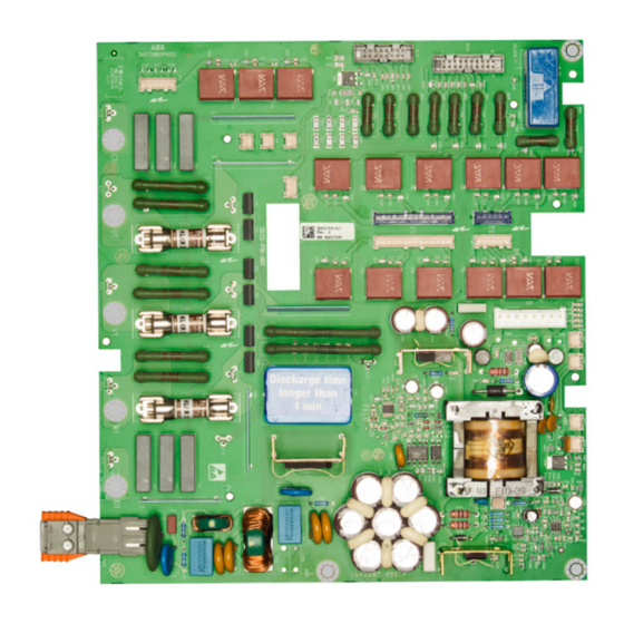
Page 123: Years Preventive Maintenance
9 years preventive maintenance Following additional actions have to take place: − Replace the power interface board SDCS- PIN-H01 of units H1 … H5 (DCS880-S0b- 0020-dd … DCS880-S0b-1190-dd). − The SDCS-PIN-H01 is located between the heat sink and the electronic tray. It operates... - Page 124 − Replace the snubber capacitors of units H8. 990 V and 1190 V only. Preventive Maintenance 3ADW000488R0101 DCS880 Service manual e a...
-
Page 125: Preventive Maintenance Checklist For Dcs880
3. Maintenance with main supply voltage applied Create parameter backup. yearly Test cooling air pressure switch. yearly Check level of all connected voltages. yearly Inspect condition of fans (check that all fans are operational). yearly Preventive Maintenance 3ADW000488R0101 DCS880 Service manual e a... - Page 126 Cooling fan frame size H1 … H6. 6 years Cooling fan frame size H7, H8. 3 years Inspect = visual inspection, correction and replacement if needed. Remarks: Date of inspection: Name of field service engineer: Preventive Maintenance 3ADW000488R0101 DCS880 Service manual e a...
-
Page 127: Appendix: Spare Parts List
Appendix: Spare Parts List Appendix: Spare Parts List 3ADW000488R0101 DCS880 Service manual e a... - Page 128 DCS Family ABB Automation Products Wallstadter-Straße 59 68526 Ladenburg • Germany Tel: +49 (0) 6203-71-0 *488R0101A7450000* Fax: +49 (0) 6203-71-76 09 *488R0101A7450000* www.abb.com/dc-drives...
Need help?
Do you have a question about the DCS880 and is the answer not in the manual?
Questions and answers