
Related Manuals for Badger Meter iSonic 4000


Summary of Contents for Badger Meter iSonic 4000
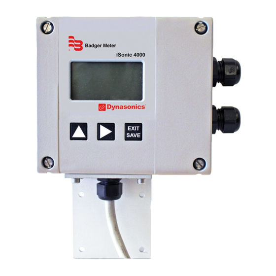
- Page 1 4000 Open-Channel Flow Meter User Manual HYB-UM-02509-EN-04 (November 2018)
- Page 2 4000, Open-Channel Flow Meter Page ii HYB-UM-02509-EN-04 November 2018...
-
Page 3: Table Of Contents
User Manual CONTENTS Scope of This Manual Safety Precautions and Instructions Installation Power Connection Protection Class Setup and Operation Cleaning Repairing Faults RoHs Battery Disposal System Description Nameplate System Settings Installation Installation the EchoPod DL-10 Sensor Mounting Positions Power Connections Auxiliary Power Operation Function Buttons... - Page 4 Main Menu Program Structure Meter Setup Measurements Inputs/Outputs Total Communications Miscellaneous Info Login Flow Meter ModBus® Register Table iSonic 4000 Flow Meter Conversion Table Rights Wiring the iSonic 4000 Meter to an ORION® Cellular LTE Endpoint Page iv HYB-UM-02509-EN-04 November 2018...
-
Page 5: Scope Of This Manual
Scope of This Manual SCOPE OF THIS MANUAL This manual contains instructions for installing, operating and programming the iSonic 4000 flow meter MPOOTANT Read this manual carefully before attempting any installation or operation. Keep the manual accessible for future reference. -
Page 6: Rohs
(flumes, weirs) or from the Q/h table The unit can also calculate flow rates in partially filled pipes and angular open channels using the Manning equation • The iSonic 4000 flow meter is an IP67 device in a robust wall-mounted metal case, with a large graphic display • The flow meter menu is operated with three front panel high endurance buttons •... -
Page 7: System Settings
System Description System Settings Flow Meter Tool Settings Settings Control Panel Driver Details November 2018 HYB-UM-02509-EN-04 Page 7... -
Page 8: Installation
Installation INSTALLATION WARNING INSTALLATION INSTRUCTIONS GIVEN IN THE FOLLOWING ARE TO BE OBSERVED IN ORDER TO PROVIDE FUNCTIONALITY AND SAFE OPERATION OF THE METER. Installation the EchoPod DL-10 Sensor Sensor EchoPod Viton Gasket 1 Insert the gasket onto the threaded end of the sensor 2 Screw the sensor into the stainless steel mounting bracket OTEE: Install the sensor at a maximum of 49 21 in (125 cm) above the flume bottom (minimal measured level) with a... -
Page 9: Mounting Positions
Power Connections Mounting Positions Manhole Flume Size Max. Flow Max. Water Level V-Mt H-Mt in. (DN) g/sec (l/sec) in. (mm) in. (mm) in. (mm) 4 (100) 1 32 (5) 5 83 (148) 23 62 (600) 5 75 (146) 6 (150) 4 23 (16) 8 94 (227) 23 62 (600) -
Page 10: Auxiliary Power
Power Connections Auxiliary Power WARNING • DO NOT CONNECT METER TO POWER SOURCE UNDER CONDITIONS THAT COULD CAUSE PERSONAL INJURY OR DAMAGE TO THE EQUIPMENT. • WIRING OF THIS EQUIPMENT MUST COMPLY WITH LOCAL AND NATIONAL CODES AND BE WITHIN THE VOLTAGE AND FREQUENCY RATING LISTED ON THE METER. - Page 11 Power Connections Configuring Input/Outputs (I/O) Auxiliary Power Solid-State Display Relay Ethernet Digital Output/Input Analog Output RS-Interface Sensor Input RS-Interface DIP switch Input/Output Description Terminal Analog output* 0…20 mA, 4…0 mA, RL < 800 Ohm, 0…10 mA 7 (+), 8 (-), 9 (GND) Digital output 1* Open collector max 10 kHz, Passive max 32V DC, <100 Hz 100 mA, >100 Hz 20 mA, 3 (-),4 (+) Active 24V DC, 20 mA, (can be powered by analog output if not used)
-
Page 12: Operation
Second screen for both applications open channel applications: Unit of Unit of Parameter Value Parameter Value Measure Measure Application Tag: iSonic 4000 Version 1.2.00 Volume 305.6 Date & Time Volume 50.3 2017-07-30 10:05 Level 0.50 m Level 0.503 m Current 10.184 mA Flow 8.85 m... -
Page 13: Setting A Pin
Setting a PIN The iSonic 4000 flow meter security feature allows the option to restrict access to the meter by way of a 6-digit Personal Identification Number (PIN) The system administrator can set up a single PIN for each of the three different levels of access: •... -
Page 14: Programming
Programming POOGOAMMING Main Menu From the Main Menu, you can access these submenus, each of which is described on the following pages: • Meter Setup • Measurements • Input and Outputs • Totalizer Reset • Communication • Miscellaneous • Information •... -
Page 15: Meter Setup Menu
Programming Meter Setup Menu Application Tank Select for a tank application Open Channel Select for an open channel application Sensor Interval Setup of time measurement interval(s); default value is 1 second; larger interval (for instance, 300 seconds) is set when unit is powered from battery WarmUpTime Powering time of sensor(s) before measurement;... -
Page 16: Measurement Menu
Programming Measurement Menu Length Establishes the unit of measure for the length Display Length Unit Feet Meter Inch Centimeter Millimeter DecimalPlaces – set of the decimal places of the Length values Flow Oate Establishes the unit of measure for the flow rate Display Flow Unit Display... - Page 17 Programming Equation Selection Q/h Table selection is possible only from the Flow Meter Tool software Display Description Exponential Eq Exponential Function Q = K h Contract Weir Contracted Weir Suppress Weir Suppressed Weir CipolettiWeir Cipoletti Weir VNotchWeir30° V Notch Weir 30° VNotchWeir45°...
- Page 18 Programming Open Channel Calculation Volumetric flow is calculated from actual water level Actual water level is limited by the maximum water level The Exponential Equation for general Parshall or Manhole flume: Q=K.Q Q – Volumetric flow [m³/s] K – Coefficient [m (3-n) h –...
- Page 19 Programming V-notch weir 45° Equation Q= 8 √ 2 • g • tan • 0.580 • (h + 0.0015) Q – Volumetric flow [m³/s] g – Standard gavity 9 80665 [m/s h – Water level [m] V-notch weir 60° Equation Q= 8 √ 2 •...
-
Page 20: Input/Outputs Menu
Programming Input/Outputs Menu Analog Output Oange Establishes the range of the analog output signal: 0…100% (= full scale) The following current output ranges are available: • 0…20 mA • 4…20 mA • 0…10 mA Analog output active Analog output passive OTEE: If an error message displays, set the current according the programing of the Alarm Mode below When you select bidirectional... - Page 21 Programming Digital Outputs You can configure functional operation of the 2 digital outputs For example, you can select Forward Pulse for the digital output and define the pulses per totalizer unit via pulse scale Digital Outputs 1 and 2 The two outputs can be operated as open collector passively or actively Passive output Active output (if analog output is not used) Solid-State Oelay...
- Page 22 Programming Digital Outputs Pulse Width This parameter establishes the ON duration of the transmitted pulse The configurable range is from 0…2000 ms If 0 ms is configured, pulse width is automatically adapted depending on pulse frequency (pulse/pause ratio 1:1) During the configuration the program checks if pulses/unit and pulse width are in accordance with full scale defined If not, an error alarm displays and scale, pulse width or full scale need to be adapted Pulse/Unit...
-
Page 23: Clear Total
Programming Figure 3: Tank volume or open-channel flow rate Clear Total Total Resets the totalizer within the ClearTot item on the Flow Meter Tool software November 2018 HYB-UM-02509-EN-04 Page 23... -
Page 24: Communications Menu
Programming Communications Menu Interfaces Modbus® RTU RS232, RS485 and RS422 with Modbus RTU Mode can be configured by DIP switches also if termination ON or OFF Modbus Address Address available from 1…247 RS232, RS422, RS485 Baudrate: 1200, 2400, 4800, 9600, 19200, 38400 Bd Parity: Even, Odd, Mark, Received Packets, Sent Packets Ethernet Modbus TCP/IP with MEAP-Header... -
Page 25: Info Menu
User logged in with this PIN will have access to both service and user-level procedures Oandom Number In case of losing PIN read the random number This number has to be sent to Badger Meter support, which is able to generate the Emergency PIN Between reading random number and entering received... -
Page 26: Troubleshooting
Troubleshooting TOOUBLESHOOTING The following error messages may display: Description Possible Cause Oecommended Action Reduce pulse scale (pulse/unit) and/or reduce Pulse Output Pulse rate exceeds the maximum pulse width configuration EEPROM Configuration file is missing Contact support Configuration Configuration file is corrupted Contact support Low Battery Low backup battery (memory) -
Page 27: Specifications
Specifications SPECIFICATIONS Type iSonic 4000 Auxiliary power 92…275V AC (50/60 Hz), < 14 VA optional 9…36V DC, < 4 W 4…20 mA, 0…20 mA, 0…10 mA ≤ 800 Ohm, active or passive; Assigned parameter depends on flow Analog output meter mode Level sensor input 4…20 mA from level sensor... -
Page 28: Dimensions
9.80 in. (249 mm) 3.15 in. (60 mm) Ø 0.20 in. (5.2 mm) 2.56 in. (65 mm) Figure 4: iSonic 4000 flow computer 2.10 in. (53.29 mm) 0.38 in. (9.7 mm) 1.00 in. (25.3 mm) 11° 11° Ø 1.34 in. -
Page 29: Main Menu Program Structure
Main Menu Program Structure MAIN MENU POOGOAM Measurements (continued) STOUCTUOE Equation Selection Table Exponential Eq Contract Weir Meter Setup Suppress Weir Cipoletti Weir Application Tank V NotchWeir30° Open Channel V NotchWeir45° Sensor Interval V NotchWeir60° Warm Up Time V NotchWeir90° Lower Range Value Manning Rect Upper Range Value... -
Page 30: Inputs/Outputs
Main Menu Program Structure Inputs/Outputs Communications Analog Output Select Range 4…20 mA Modbus MODBUS Address 0…20 mA RS-232/422/485 Baud Rate 1200 0…10 mA 2400 Alarm Mode 4800 23 mA 9600 3 5 mA 19200 Compensation 38400 Digital Input 115200 Remote Reset Parity Even Pos Zero Reset... -
Page 31: Flow Meter Modbus® Register Table
FLOW METEO MODBUS® OEGISTEO TABLE Address Oegisters Oights Name iSonic 0x0000 Read only PRODUCT_CODE 7: iSonic 0x0001 Read only PRODUCT_NAME “iSonic 4000” 0x0009 Read only FW_NAME "iSonic_A_STM32F107RC" 0x0019 Read only APP_VERSION Version 0x0023 Read only COMPILATION_DATE Date of compilation 0x0033... - Page 32 Flow Meter ModBus® Register Table Address Oegisters Oights Name iSonic 1: save configuration 2: restore configuration 6: save totalizers 7: clear totalizers 8: clear totalizers 14: current loop calibration point A 15: current loop calibration point B 16: current loop calibration complete 22: default save 23: remote reset 0x0125...
- Page 33 Flow Meter ModBus® Register Table Address Oegisters Oights Name iSonic 0x0206 Service OUT_HIGH OBSOLETE 0x0226 Service DATETIME Date & Time Bit0: Low Battery Bit1: Measure Timeout Bit2: Table Error Bit6: Flow Overload Warning 0x0232 Read only FAULT Bit7: Disk Error Bit8: Configuration Error Bit9: Pulse Overload Warning Bit10: Sensor Disconnected Error...
- Page 34 Flow Meter ModBus® Register Table Address Oegisters Oights Name iSonic 40 Gallons 41 Liters 42 Imperial Gallons 43 Cubic Meters 0x0303 User UNITCODES_VOLUME 46 Barrels 112 Cubic Feet 236 Hectoliters 240 Mega Gallons 241 Acre Feet 0x0304 User DECIMALPLACES_LENGTH Number of decimal places of length Number of decimal places of 0x0305 User...
-
Page 35: Isonic 4000 Flow Meter Conversion Table
0x041A Float Admin Open channel calibration ACTUALUNIT OPENCHANNEL_ SURFACEROUGHNESS_ 0x041C Float Admin Open channel calibration ACTUALUNIT iSonic 4000 Flow Meter Conversion Table Address Oegisters Oights Oead Write Name Note 0x0500 Float, Float Admin Conversion Table Point 0 Water Level [m], Volume [m³] or Flow[m³/s] …... -
Page 36: Wiring The Isonic 4000 Meter To An Orion® Cellular Lte Endpoint
The Americas | Badger Meter | 4545 West Brown Deer Rd | PO Box 245036 | Milwaukee, WI 53224-9536 | 800-876-3837 | 414-355-0400 México | Badger Meter de las Americas, S.A. de C.V. | Pedro Luis Ogazón N°32 | Esq. Angelina N°24 | Colonia Guadalupe Inn | CP 01050 | México, DF | México | +52-55-5662-0882 Europe, Eastern Europe Branch Office (for Poland, Latvia, Lithuania, Estonia, Ukraine, Belarus) | Badger Meter Europe | ul.
Need help?
Do you have a question about the iSonic 4000 and is the answer not in the manual?
Questions and answers