
Related Manuals for WIKA CPT6010


Summary of Contents for WIKA CPT6010
- Page 1 Operating Instructions Digital Pressure Transducer CPT6010 Digital Pressure Transducer CPT6010 PN 0017063001U • 12/2018...
- Page 2 This Caution symbol indicates danger for the system and material if the respective safety precautions are not taken. Caution This Notice symbol does not indicate safety notices but information for a better understanding of the facts. Notice CPT6010 Operating Instructions...
-
Page 3: Table Of Contents
3.4 Sensor 3.5 Circuitry 3.6 Serial In/Out Communications 4. Specifications 5. Installation 5.1 Unpacking the instrument 5.2 Dimensions 5.3 Configuration 5.4 Mounting 5.5 Pressure Connections 5.6 Electrical Connections 5.6.1 Connector J1 Wiring 5.6.2 RS-232 Operation 5.6.3 RS-485 Operation CPT6010 Operating Instructions... - Page 4 CPT6010 6. Operation 6.1 Multiple Turndown Devices 6.1.1 Filter Effects of Multiple Turndowns 6.2 Serial Port Configuration 6.3 CPT6010 Address 6.3.1 Addressing Devices with two Turndowns 6.4 Communication Syntax and Command Conventions 6.4.1 Wildcard Address Operator (*) 6.4.2 Password Protection 6.4.3 Response String Format...
-
Page 5: General Information
Mensor has made a concerted effort to provide complete and current information for the proper use of the equipment. If there are questions regarding this manual or the proper use of the equipment, contact either Mensor or WIKA: Mensor WIKA Alexander Wiegand SE & Co. KG 201 Barnes Drive Alexander-Wiegand-Straße 30 San Marcos, TX 78666... -
Page 6: Software License Agreement
20,000 psi, for all of your pressure instruments. This service includes an accredited calibration. 1.4.3 Accreditations Mensor is registered to ISO 9001:2008. The calibration program at Mensor is accredited by A2LA, as complying with both the ISO/IEC 17025:2005 and the ANSI/NCSL Z540-1-1994 standards. 2. Safety Notices CPT6010 Operating Instructions... -
Page 7: Warnings And Caution Notices
(printed circuit boards) to prevent static discharge to sensitive electronic components. Avoid excessive overpressure to the sensor! Externally mounted relief valves to provide overpressure protection are available from Mensor as optional devices and are highly recommended for very low pressure trans- ducers. Caution CPT6010 Operating Instructions... - Page 8 Digital Pressure Transducer CPT6010 NOTES CPT6010 Operating Instructions...
-
Page 9: Product Description
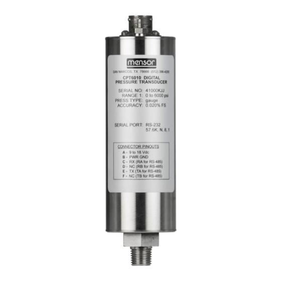
Communication with the CPT6010 is over a serial bus, either RS-232 or RS-485. One end of the CPT6010 has a 1/4” NPT male fitting pressure port, and the opposite end has a six pin power/signal connector (J1) and a #10-32 reference pressure port (for gauge pressure only). - Page 10 Digital Pressure Transducer CPT6010 9 to18 VDC Figure 3.6 - CPT6010 Block Diagram CPT6010 Operating Instructions...
-
Page 11: Specifications
All seawater units are 3.5% salinity. Resolution From 1 to 10 ppm, depending on measurement units and range Overpressure Ratings 150% FS or greater, depending on range Compensated Temperature 15°C to 45°C Range Warm-up 10 minutes to rated accuracy CPT6010 Operating Instructions... - Page 12 (LabVIEW® is a trademark of National Instruments Corporation.) Max Transmission 4000 feet (RS-485) Multi-drop Capacity The maximum number of RS-485 CPT6010 transducers which can be connected to a single host computer is 31. Mechanical Shock 5g max Case Size 1.74” wide x 6.3” long (4.42 x 16 cm), not including pneumatic and electrical connectors.
-
Page 13: Installation
However, excessive motor or machinery vibration of the mounting surface should be avoided to further ensure stability and accuracy. For the greatest accuracy on transducers with a full scale range of less than 15 psi, set CPT6010 zero while it is oriented in its operational position. 5.5 Pressure Connections... -
Page 14: Pressure Connections
For RS-232 serial port operation, connect the CPT6010 to the host computer per Figure 5.6.2 No- tice that the host TRANSMIT line is connected to the CPT6010 RECEIVE line (TX to RX), and vice versa. One limitation of the RS-232 bus is that a host can support only one instrument. See section 5.6.3, RS-485 Operation, for multiple CPT6010 operation. -
Page 15: Rs-485 Operation
TA to RA, TB to RB, and so on. If only one RS-485 CPT6010 will be connected to the system, disregard the wiring to “CPT #1” and “CPT #2” in the illustrations. Instead, wire the computer directly to the “CPT #31” by the four-wire method. - Page 16 Digital Pressure Transducer CPT6010 Figure 5.6.3 - RS-485 Cabling CPT6010 Operating Instructions...
-
Page 17: Operation
Digital Pressure Transducer CPT6010 6. Operation The pressure to be measured is applied to the 1/4 NPT fitting on the CPT6010. Avoid excessive overpressure to the sensor! Externally mounted relief valves to provide overpressure protection are available from Mensor as optional devices, and are highly recommended for very low pressure transducers. -
Page 18: Serial Port Configuration
6.2 Serial Port Configuration Unless otherwise requested by the customer, the CPT6010 serial ports are set at the factory to the default values listed in the following table. Table 6.2 - Serial Port Settings... -
Page 19: Communication Syntax And Command Conventions
However, this wildcard must not be used in queries if more than one transducer is con- nected to a host. One use for the wildcard address could be when a CPT6010 is pulled out of a multi-drop setup and sent to a calibration facility for recertification. The calibration technician can communicate with the device using the wildcard address without learning or changing its assigned address. -
Page 20: Commands And Queries
#XFL?<cr> X<sp>FL<sp>nn<cr> Returns the filter – it is the per- <lf> centage of old reading added to new reading: 0-99. #XFL<sp>nn<cr> Sets the filter percentage. #XFS?<cr> X<sp>FS<sp>nnnnn<cr> Returns the %FS accuracy. <lf> CPT6010 Operating Instructions... -
Page 21: Pressure Unit Code And Conversion
Sets zero correction value in n<cr> current units. 6.4.5 Pressure Unit Code and Conversion Table 6.4.5 - Pressure Unit Code and Conversion Code Unit PSI Conversion Factor inHg@0°C 2.036020 2.041772 inHg@60°F inH2O@4°C 27.68067 inH2O@20°C 27.72977 inH2O@60°F 27.70759 CPT6010 Operating Instructions... -
Page 22: Calibration
0.07030697 mSW @ 0°C (3.5% salinity) 0.6838528 oz/in2 0.072 % Full Scale microns Hg @ 0°C 51715.08 0.0005 68.94757 0.006894757 7. Calibration The CPT6010 automatically adjusts the pressure readings for the effects of temperature and non- CPT6010 Operating Instructions... -
Page 23: Environment
The temperature should be stable, and within the specified calibration range. In addition, for maximum accuracy, see that the CPT6010 is at rest on a stable platform which is free of vibration and shock, and oriented similar to its final installation attitude. At the factory the CPT6010 is calibrated vertically with the pressure port at the bottom. - Page 24 LINE SHUT-OFF REGULATOR VALVES Computer METERING VENT VALVE VOLUME CONTROLLER Serial VACUUM Cable Absolute Pressure CPT6010 PRESSURE PRESS PRESSURE NOTE: DISCONNECT WHEN VACUUM DIAPHRAGM TYPE STANDARD GAUGE RANGE IS EXCEEDED VACUUM GAUGE Figure 7.2 - Calibration Setup CPT6010 Operating Instructions...
-
Page 25: Pressure Standard
Depending on the specific language used to generate them, these commands may have to be preceded by or enclosed in various symbols for transmission. For this procedure it is assumed that a single CPT6010 is connected to the host computer, and that its assigned address is unknown. -
Page 26: Zero Adjustment
Send: #*PW<cr><lf> Next send the zero offset: #*ZC<sp>–.0023<cr><lf> The new offset of –0.0023 will now be added to all pressure readings of the CPT6010. Send: #*SAVE<cr><lf> to store the new value in non-volatile memory. 6. To check the zero correction: Send: #*?<cr><lf>... -
Page 27: Absolute Zero Offset
2. Use the setup for absolute pressure shown in Figure 7.2. Apply a stable pressure value between 600 mTorr absolute and 20% of the transducer’s span.Measure the reference presure reading in the native units of the CPT6010. This reading becomes the “true pressure”. 3. Clear the current zero offset from RAM. -
Page 28: Span Adjustment
2. To clear the current scale factor: Send: #*PW<cr><lf> Next send: #*SC<sp>1<cr><lf> 3. Apply a known true pressure equal to the span of the CPT6010. To determine the CPT6010 pressure reading: Send: #*?<cr><lf> and make a note of this reading. - Page 29 Digital Pressure Transducer CPT6010 NOTESpas CPT6010 Operating Instructions...
- Page 30 San Marcos, Texas 78666 Tel: 512-396-4200 Fax: 512-396-1820 sales@mensor.com www.mensor.com CPT6010 Operating Instructions PN 0017063001T • 07/2018 WIKA Alexander Wiegand SE & Co. KG Alexander-Wiegand-Straße 30 D-63911 Klingenberg / Germany Tel: +49 93 72/132-5015 Fax: +49 93 72/132-8767 CTSales@wika.de www.wika.de...
Need help?
Do you have a question about the CPT6010 and is the answer not in the manual?
Questions and answers