Table of Contents
Advertisement
Available languages
Available languages
Quick Links
Advertisement
Chapters
Table of Contents

Related Manuals for WIKA F2221


Summary of Contents for WIKA F2221
- Page 1 Operating instructions Betriebsanleitung Tension/compression force transducer with external thread Models F2220, F2221, F2226 Zug-/Druckkraftaufnehmer mit Außengewinde Typen F2220, F2221, F2226 Models F2221, F2226...
- Page 2 Operating instructions models F2220, F2221, F2226 Page 3 - 26 Betriebsanleitung Typen F2220, F2221, F2226 Seite 27 - 51 © 10/2020 WIKA Alexander Wiegand SE & Co. KG All rights reserved. / Alle Rechte vorbehalten. WIKA is a registered trademark in various countries. ®...
-
Page 3: Table Of Contents
2. Design and function 2.1 Overview models F2220, F2221 ....5 2.2 Overview model F2226 ....5 3. -
Page 4: General Information
Two connection lines are used for the voltage supply. One connection line is used for the measuring signal. Positive power supply terminal Negative power supply terminal Positive output terminal Negative output terminal Shield Case WIKA operating instructions, models F2220, F2221, F2226... -
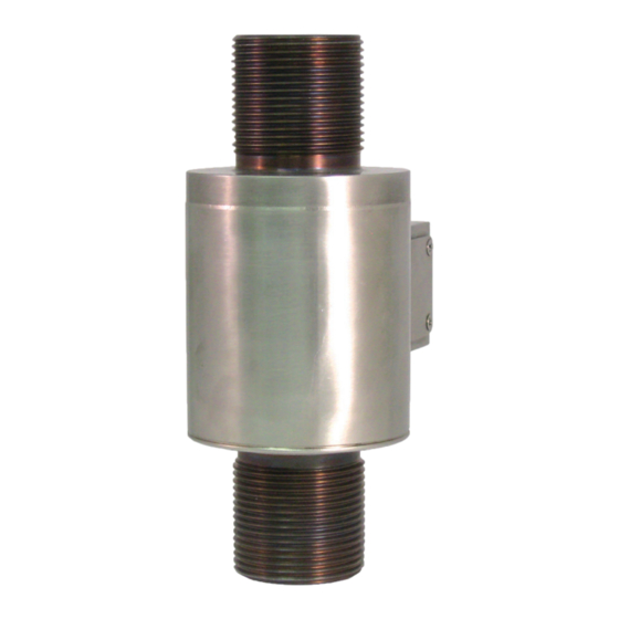
Page 5: Design And Function
Force introduction Measuring spring Electrical connection 2.2 Overview model F2226 Force introduction Measuring spring Electrical connection Counter nuts WIKA operating instructions, models F2220, F2221, F2226... -
Page 6: Safety
... indicates a potentially dangerous situation that can result in light injuries or damage to property or the environment, if not avoided. Information ... points out useful tips, recommendations and information for efficient and trouble-free operation. WIKA operating instructions, models F2220, F2221, F2226... -
Page 7: Intended Use
Connectors, stranded wires and sockets must be protected from contamination. The manufacturer shall not be liable for claims of any type based on operation contrary to the intended use. WIKA operating instructions, models F2220, F2221, F2226... -
Page 8: Improper Use
■ intended use. that personal protective equipment is available. ■ WIKA operating instructions, models F2220, F2221, F2226... -
Page 9: Personnel Qualification
The operator is in no way relieved of his obligations under labour law for the safety and the protection of workers' health. The design of the personal protective equipment must take into account all operating parameters of the place of use. WIKA operating instructions, models F2220, F2221, F2226... -
Page 10: Labelling, Safety Marks
Manufacturer logo Serial number Ingress protection per DIN EN 60529 Pin assignment Manufacturer address Force direction Supply voltage Output signal Measuring range Product code WIKA operating instructions, models F2220, F2221, F2226... -
Page 11: Transport, Packaging And Storage
Mechanical vibration, mechanical shock (putting it down hard) ■ Dust, dirt, and other objects may not be deposited in such a way that they form a ■ force shunt with the measuring spring, since this will falsify the measuring signal. WIKA operating instructions, models F2220, F2221, F2226... -
Page 12: Commissioning, Operation
The supplied counter nuts for model F2226 must never rest on the deformation element. A gap of at least 0.5 mm must be provided. ▶ With models F2220 and F2221, the device must not touch the deformation element. WIKA operating instructions, models F2220, F2221, F2226... -
Page 13: Installation Of The Tension/Compression Force Transducer
Observe the max. torque. Screw the matching part of the measuring object onto the free thread. As necessary, secure with counter nut. Observe the max. torque. Load the force transducer. WIKA operating instructions, models F2220, F2221, F2226... -
Page 14: Installation Of The Tension/Compression Force Transducer With Swivel Heads
Tighten counter nuts. Observe the max. Place the swivel heads in the clamping torque. device and fix with retaining bolts. The retaining bolts must not restrict the free location of the force transducer. Load the force transducer. WIKA operating instructions, models F2220, F2221, F2226... -
Page 15: Electrical Connection
Signal (+) White Signal (-) Green 5.8 Pin assignment model F2226 Electrical connection mV/V connector Excitation voltage (+) Pin A&B Excitation voltage (-) Pin C&D Signal (+) Pin F Signal (-) Pin E WIKA operating instructions, models F2220, F2221, F2226... -
Page 16: Faults
Signal span varies EMC interference sources in Shield instrument; cable the environment; for example, shield; remove source of frequency converter interference Signal span drops/too small Mechanical overload Consult the manufacturer WIKA operating instructions, models F2220, F2221, F2226... -
Page 17: Maintenance And Cleaning
DAkkS certificate - official certificates: We recommend that the tension/compression force transducer is recalibrated by the manufacturer at regular time intervals of approx. 24 months. The basic settings will be corrected if necessary. WIKA operating instructions, models F2220, F2221, F2226... -
Page 18: Dismounting, Return And Disposal
8.2 Return Strictly observe the following when shipping the instrument: All instruments delivered to WIKA must be free from any kind of hazardous substances (acids, bases, solutions, etc.) and must therefore be cleaned before being returned. When returning the instrument, use the original packaging or a suitable transport packaging. -
Page 19: Specifications
DC 12 … 28 V for output 0(4) … 20 mA, DC 0 … 10 V Protection (acc. to IEC/EN 60529) IP65 Weight 5 g up to 30 g depending on rated force Calibration (standard) Positive in tension WIKA operating instructions, models F2220, F2221, F2226... - Page 20 4-wire, length ~ 50 cm Threads at both ends Dimensions in mm Rated force in N ØD 10, 20, 50, 100, 200, 500 12.7 M3 x 0.5 1,000, 2,000, 5,000 19.1 M6 x 1.0 WIKA operating instructions, models F2220, F2221, F2226...
- Page 21 DC 12 … 28 V for output 0(4) … 20 mA, DC 0 … 10 V Protection (acc. to IEC/EN 60529) IP65 Weight 20 g up to 250 g depending on rated force WIKA operating instructions, models F2220, F2221, F2226...
- Page 22 12.7 6.35 10,000 25.4 18.3 12.7 0.76 M10 x 1.5 12.7 6.35 31.8 23.9 16.0 0.76 M12 x 1.5 12.7 9.65 20,000 30,000, 50,000 35.1 27.9 22.35 0.76 M20 x 1.5 12.7 9.65 WIKA operating instructions, models F2220, F2221, F2226...
- Page 23 Protection (acc. to IEC/EN 60529) Options Force introduction components ■ Integrated amplifier ■ Extended temperature ranges ■ Other thread sizes ■ Other bridge resistance ■ Connector / plug protection ■ Internal / external thread ■ WIKA operating instructions, models F2220, F2221, F2226...
- Page 24 77.5 76.2 88.9 1,000 M100 x 3 139.7 101.6 114.3 1,500 M100 x 3 139.7 114.3 127.0 2,000, 2,200 M120 x 4 146.1 127.0 139.7 3,000, 3,300 M150 x 4 139.7 171.5 168.4 WIKA operating instructions, models F2220, F2221, F2226...
-
Page 25: Approvals
9.1 Approvals Logo Description Country European Union EU declaration of conformity EMC directive ■ RoHS directive ■ Eurasian Economic Community EMC directive ■ 10. Accessories WIKA accessories can be found online at www.wika.com. WIKA operating instructions, models F2220, F2221, F2226... -
Page 26: Annex: Eu Declaration Of Conformity
Annex: EU declaration of conformity WIKA operating instructions, models F2220, F2221, F2226... - Page 27 2. Aufbau und Funktion 2.1 Überblick Typen F2220, F2221 ....29 2.2 Überblick Typ F2226 ....29 3.
-
Page 28: Allgemeines
2-Leiter Die zwei Anschlussleitungen dienen zur Spannungsversorgung. Der Speisestrom ist das Messsignal. 3-Leiter Zwei Anschlussleitungen dienen zur Spannungsversorgung. Eine Anschlussleitung dient für das Messsignal. Positiver Versorgungsanschluss Negativer Versorgungsanschluss Positiver Messanschluss Negativer Messanschluss Schirm Gehäuse WIKA Betriebsanleitung, Typen F2220, F2221, F2226... -
Page 29: Aufbau Und Funktion
2.1 Überblick Typen F2220, F2221 Krafteinleitung Messfeder Elektrischer Anschluss 2.2 Überblick Typ F2226 Krafteinleitung Messfeder Elektrischer Anschluss Kontermuttern WIKA Betriebsanleitung, Typen F2220, F2221, F2226... -
Page 30: Symbolerklärung
... weist auf eine möglicherweise gefährliche Situation hin, die zu geringfü- gigen oder leichten Verletzungen bzw. Sach- und Umweltschäden führen kann, wenn sie nicht gemieden wird. Information ... hebt nützliche Tipps und Empfehlungen sowie Informationen für einen effizienten und störungsfreien Betrieb hervor. WIKA Betriebsanleitung, Typen F2220, F2221, F2226... -
Page 31: Bestimmungsgemäße Verwendung
Stößen, starken Magnetfeldern, statischer Elektrizität und extremen Temperaturen schützen, keine Gegenstände in das Gerät bzw. Öffnungen einführen). Stecker, Litzen und Buchsen vor Verschmutzung schützen. Ansprüche jeglicher Art aufgrund von nicht bestimmungsgemäßer Verwendung sind ausgeschlossen. WIKA Betriebsanleitung, Typen F2220, F2221, F2226... -
Page 32: Fehlgebrauch
Arbeitssicherheit, Erste Hilfe und Umweltschutz unterwiesen wird, sowie die Betriebsanleitung und insbesondere die darin enthaltenen Sicherheitshinweise kennt. dass das Gerät gemäß der bestimmungsgemäßen Verwendung für den ■ Anwendungsfall geeignet ist. dass die persönliche Schutzausrüstung verfügbar ist. ■ WIKA Betriebsanleitung, Typen F2220, F2221, F2226... -
Page 33: Personalqualifikation
Der Betreiber wird durch diese Vorschläge in keiner Weise von seinen arbeitsrechtlichen Pflichten zur Sicherheit und dem Schutz der Gesundheit der Arbeit- nehmer entbunden. Die Bemessung der persönlichen Schutzausrüstung muss unter Berücksichtigung aller Betriebsparameter des Einsatzortes erfolgen. WIKA Betriebsanleitung, Typen F2220, F2221, F2226... -
Page 34: Beschilderung, Sicherheitskennzeichnungen
Herstellerlogo Seriennummer Schutzart gem. DIN EN 60529 Anschlussbelegung Herstelleradresse Kraftrichtung Speisespannung Ausgangssignal Messbereich Produktcode WIKA Betriebsanleitung, Typen F2220, F2221, F2226... -
Page 35: Transport, Verpackung Und Lagerung
Folgende Einflüsse vermeiden: Mechanische Vibration, mechanischer Schock (hartes Aufstellen) ■ Staub, Schmutz und sonstige Gegenstände dürfen sich nicht so ablagern, dass ■ sie einen Kraftnebenschluss zur Messfeder bilden, da dadurch das Messsignal verfälscht wird. WIKA Betriebsanleitung, Typen F2220, F2221, F2226... -
Page 36: Inbetriebnahme, Betrieb
Die mitgelieferten Kontermuttern bei Typ F2226 dürfen in keinem Fall am Verfor- mungskörper anliegen. Ein Spalt von 0,5 mm ist mindestens vorzusehen. ▶ Bei den Typen F2220 und F2221 darf die Vorrichtung nicht am Verformungskörper anliegen. WIKA Betriebsanleitung, Typen F2220, F2221, F2226... -
Page 37: Montage Des Zug-/Druckkraftaufnehmers
Bei Bedarf mit Kontermutter kontern. Gewinde des Kraftaufnehmers aufschrau- Max. Drehmoment beachten. ben. Gegenstück des Messobjekts auf freies Gewinde aufschrauben. Gegebenfalls mit Kontermutter kontern. Max. Drehmoment beachten. Kraftaufnehmer belasten. WIKA Betriebsanleitung, Typen F2220, F2221, F2226... -
Page 38: Montage Des Zug-/Druckkraftaufnehmers Mit Gelenkköpfen
Gelenkköpfe in Haltevorrichtungen positi- Kontermuttern kontern. Max. Drehmoment onieren und mit Haltebolzen fixieren. Die beachten. Haltebolzen dürfen die freie Lagerung des Kraftaufnehmers nicht beeinträchtigen. Kraftaufnehmer belasten. WIKA Betriebsanleitung, Typen F2220, F2221, F2226... -
Page 39: Elektrischer Anschluss
Speisespannung (-) Schwarz Signal (+) Weiß Signal (-) Grün 5.8 Anschlussbelegung Typ F2226 Elektrischer Anschluss mV/V - Stecker Speisespannung (+) Pin A&B Speisespannung (-) Pin C&D Signal (+) Pin F Signal (-) Pin E WIKA Betriebsanleitung, Typen F2220, F2221, F2226... -
Page 40: Störungen
Mechanische Überlastung, Rücksprache mit Hersteller signals bei Kraftänderung falsche Anschlussbelegung Signalspanne schwankend EMV-Störquellen in Gerät abschirmen; Leitungs- Umgebung, z. B. Frequenz- abschirmung; Störquelle umrichter entfernen Signalspanne fällt ab/zu klein Mechanische Überlastung Rücksprache mit Hersteller WIKA Betriebsanleitung, Typen F2220, F2221, F2226... -
Page 41: Wartung Und Reinigung
Keine harten und spitzen Gegenstände zur Reinigung verwenden. 7.3 Rekalibrierung DAkkS-Schein - amtliche Bescheinigungen: Es wird empfohlen, den Zug-/Druckkraftaufnehmer in regelmäßigen Zeitabständen von ca. 24 Monaten durch den Hersteller rekalibrieren zu lassen. Die Grundeinstellungen werden wenn notwendig korrigiert. WIKA Betriebsanleitung, Typen F2220, F2221, F2226... -
Page 42: Demontage, Rücksendung Und Entsorgung
Einbausituation entfernen. 8.2 Rücksendung Beim Versand des Gerätes unbedingt beachten: Alle an WIKA gelieferten Geräte müssen frei von Gefahrstoffen (Säuren, Laugen, Lösungen, etc.) sein und sind daher vor der Rücksendung zu reinigen. Zur Rücksendung des Gerätes die Originalverpackung oder eine geeignete Transportverpackung verwenden. -
Page 43: Technische Daten
DC 2 … 5 V (max. 5 V) für mV/V-Ausgang mit Kabelmessverstärker DC 12 … 28 V für Ausgang 0(4) … 20 mA, DC 0 … 10 V Schutzart (nach IEC/EN 60529) IP65 Ca. 5 g bis 30 g je nach Nennkraft Gewicht WIKA Betriebsanleitung, Typen F2220, F2221, F2226... - Page 44 PTFE-isolierte Litzen, Länge ca. 50 cm Gewinde an beiden Enden Abmessungen in mm Nennkraft in N ØD 10, 20, 50, 100, 200, 500 12,7 M3 x 0,5 1.000, 2.000, 5.000 19,1 M6 x 1,0 WIKA Betriebsanleitung, Typen F2220, F2221, F2226...
- Page 45 Kabelmessverstärker DC 12 … 28 V für Ausgang 0(4) … 20 mA, DC 0 … 10 V Schutzart (nach IEC/EN 60529) IP65 Gewicht Ca. 20 g bis 250 g je nach Nennkraft WIKA Betriebsanleitung, Typen F2220, F2221, F2226...
- Page 46 M6 x 1,0 12,7 6,35 10.000 25,4 18,3 12,7 0,76 M10 x 1,5 12,7 6,35 31,8 23,9 16,0 0,76 M12 x 1,5 12,7 9,65 20.000 30.000, 50.000 35,1 27,9 22,35 0,76 M20 x 1,5 12,7 9,65 WIKA Betriebsanleitung, Typen F2220, F2221, F2226...
- Page 47 DC 0 … 10 V mit Kabelmessverstärker Schutzart (nach IEC/EN 60529) IP66 Optionen Krafteinleitungsteile ■ Integrierter Messverstärker ■ Erweiterte Temperaturbereiche ■ Andere Gewindegrößen ■ Anderer Brückenwiderstand ■ Anschluss- / Steckerschutz ■ Innen- / Außengewinde ■ WIKA Betriebsanleitung, Typen F2220, F2221, F2226...
- Page 48 M56 x 4 77,5 76,2 88,9 1.000 M100 x 3 139,7 101,6 114,3 1.500 M100 x 3 139,7 114,3 127,0 2.000, 2.200 M120 x 4 146,1 127,0 139,7 3.000, 3.300 M150 x 4 139,7 171,5 168,4 WIKA Betriebsanleitung, Typen F2220, F2221, F2226...
-
Page 49: Zulassungen
9. Technische Daten / 10. Zubehör 9.1 Zulassungen Logo Beschreibung Land Europäische Union EU-Konformitätserklärung EMV-Richtlinie ■ RoHS-Richtlinie ■ Eurasische Wirtschaftsgemeinschaft EMV-Richtlinie ■ 10. Zubehör WIKA-Zubehör finden Sie online unter www.wika.de. WIKA Betriebsanleitung, Typen F2220, F2221, F2226... -
Page 50: Anlage: Eu-Konformitätserklärung
Anlage: EU-Konformitätserklärung WIKA Betriebsanleitung, Typen F2220, F2221, F2226... - Page 51 WIKA Betriebsanleitung, Typen F2220, F2221, F2226...
- Page 52 WIKA subsidiaries worldwide can be found online at www.wika.com. Sales contact: WIKA Alexander Wiegand SE & Co. KG Alexander-Wiegand-Straße 30 63911 Klingenberg • Germany Tel. +49 9372 132-0 +49 9372 132-406 info@wika.de www.wika.de WIKA operating instructions, models F2220, F2221, F2226...
Need help?
Do you have a question about the F2221 and is the answer not in the manual?
Questions and answers