
Related Manuals for Emerson Fisher FLOBOSS 407


Summary of Contents for Emerson Fisher FLOBOSS 407
- Page 1 Field Automation Systems FLOBOSS™ 407 FLOW MANAGER Instruction Manual Form A6013 May 2000 Loose-leaf version: Part Number D301080X012 Bound version: Contact FAS...
- Page 2 FloBoss 407 Instruction Manual Revision Tracking Sheet May 2000 This manual may be revised periodically to incorporate new or updated information. The date revision level of each page is indicated at the bottom of the page opposite the page number. A major change in the content of the manual also changes the date of the manual which appears on the front cover.
-
Page 3: Table Of Contents
FloBoss 407 Instruction Manual Table of Contents (For a more detailed listing, see the Section Contents at the front of each section.) SECTION 1 — GENERAL INFORMATION ............1-1 1.1 Scope of Manual ..........................1-1 1.2 Section Contents ..........................1-2 1.3 Product Overview ..........................1-2 1.4 Installation Guidelines ........................1-5 1.5 Power Consumption Calculation ......................1-9 1.6 Startup and Operation ........................1-13... - Page 4 FloBoss 407 Instruction Manual Table of Contents (Continued) SECTION 4 — COMMUNICATIONS CARDS ............4-1 4.1 Scope..............................4-1 4.2 Product Descriptions.........................4-1 4.3 Initial Installation and Setup ......................4-8 4.4 Connecting Communication Cards to Wiring ................4-11 4.5 Troubleshooting and Repair ......................4-18 4.6 Communications Card Specifications.....................4-20 SECTION 5 —...
- Page 5 FloBoss 407 Instruction Manual Table of Contents (Continued) B.4 Field Wiring............................. B-7 B.5 Configuration..........................B-13 B.6 Calibration ............................. B-14 B.7 MVS Troubleshooting and Repair....................B-18 B.8 Specifications..........................B-19 APPENDIX C — I/O SIMULATION ................. C-1 C.1 Scope..............................C-1 C.2 Analog Outputs to Analog Inputs ....................C-1 C.3 Analog Outputs to a meter.......................
- Page 6 FloBoss 407 Instruction Manual [This page is intentionally left blank.] Rev 5/00...
-
Page 7: Section 1 - General Information
FloBoss 407 Instruction Manual SECTION 1 — GENERAL INFORMATION 1.1 SCOPE OF MANUAL ™ This manual describes the FloBoss 407 Flow Manager (also called the ROC407), part of the family of FloBoss Flow Managers manufactured by Fisher Controls. Both the Standard version and the Measurement Canada version of the FloBoss 407 are covered in this manual. -
Page 8: Section Contents
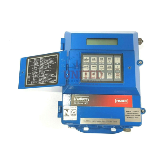
FloBoss 407 Instruction Manual 1.2 SECTION CONTENTS This section contains the following information: Information Section Page Number Product Overview Related Documents and Compatibility 1.3.1 Installation Guidelines Environmental Requirements 1.4.1 Site Requirements 1.4.2 Compliance with Hazardous Area Standards 1.4.3 Power Installation Requirements 1.4.4 Grounding Installation Requirements 1.4.5... - Page 9 FloBoss 407 Instruction Manual Figure 1-1. FloBoss 407 Flow Manager Physically, the FloBoss 407 consists of two printed circuit cards, a keypad, and a display housed in a compact weather-tight case. The printed circuit cards are the processor board and the termination board.
-
Page 10: Related Documents And Compatibility
FloBoss 407 Instruction Manual The FloBoss has two communication ports built in: a local operator interface port and an EIA-232 serial port. A variety of optional plug-in communication cards are available that allow you to add another communications channel: EIA-232 serial, EIA-422/485 serial, dial-up modem, radio modem, or leased-line modem communications. -
Page 11: Installation Guidelines
FloBoss 407 Instruction Manual For accessories, refer to the following manual: ♦ ROC/FloBoss Accessories Instruction Manual (Form A4637) – Provides information concerning accessories such as RTD sensors for the MVS. 1.4 INSTALLATION GUIDELINES This manual provides generalized guidelines for successful installation and operation of the FloBoss 407. -
Page 12: Compliance With Hazardous Area Standards
FloBoss 407 Instruction Manual ♦ Locate the FloBoss 407 to minimize the length of signal and power wiring. By Code, line power wiring must not cross meter runs. ♦ Orient solar panels used with solar-powered FloBoss 407s to face True South (not magnetic) in Northern hemispheres. -
Page 13: Power Installation Requirements
FloBoss 407 Instruction Manual When installing units in a hazardous area, make sure components selected are labeled for use in such areas. Installation and maintenance must be performed only when the area is known to be non-hazardous. NOTE Measurement Canada approved units normally require a sealed installation. Refer to your local codes for specifics. -
Page 14: I/O Wiring
FloBoss 407 Instruction Manual The National Electrical Code Article 250-95 (1993) defines the size requirements for equipment grounding conductors. Proper grounding of the FloBoss 407 helps to reduce the effects of electrical noise on the units operation and protects against lightning. Lightning Protection Modules (LPM) are available to provide additional lightning protection for field wiring inputs and outputs. -
Page 15: Power Consumption Calculation
FloBoss 407 Instruction Manual 1.5 POWER CONSUMPTION CALCULATION A ROC/FloBoss system’s power consumption determines power supply and battery sizing for both line and solar power supplies. Table 1-1 and Table 1-2 provide information to assist in determining power requirements. For non-analog I/O, size the I/O module scaling resistors (see Section 3) for optimal current to minimize current drain on the power supply. -
Page 16: Radio Modem
FloBoss 407 Instruction Manual Table 1-1. Power Consumption of the FloBoss 407 and Powered Devices POWER CONSUMPTION (mW) DUTY SUB- DEVICE 12V System 24V System CYCLE TOTAL (mW) Processor and I/O Termination Board 1200 (includes minimum built-in I/O power consumption) Built-in Analog Input —... - Page 17 FloBoss 407 Instruction Manual Table 1-2. Power Consumption of the I/O Modules POWER CONSUMPTION (mW) DUTY SUB- I/O MODULE 12V System 24V System CYCLE TOTAL (mW) AI Loop AI Differential AI Source AO Source RTD Input (P is at -50° C; is at 100°...
-
Page 18: Determining Radio Power Consumption
FloBoss 407 Instruction Manual 1.5.2 Determining Radio Power Consumption In determining power requirements for radios, the duty cycle for the radio must be estimated. The duty cycle is the percentage of time the radio is transmitting (TX). For example, if a radio is transmitting 1 second out of every 60 seconds, and for the remaining 59 seconds the radio is drawing receive (RX) power, the duty cycle is: Duty Cycle = TX time/(TX time + RX time) = 1 sec/60 sec = 0.0167... -
Page 19: Startup And Operation
FloBoss 407 Instruction Manual 1.6 STARTUP AND OPERATION Before starting the FloBoss 407, perform the following checks to ensure the unit is properly installed. ♦ Make sure the enclosure has a good earth ground connected to the earth ground bus inside the enclosure. -
Page 20: Keypad Operation
FloBoss 407 Instruction Manual 1.7 KEYPAD OPERATION Table 1-3 provides a brief description of the keypad functions and the expected displays. For a detailed description, refer to Section 5 of this manual. To activate the display, press any key, for example . -
Page 21: Service Bulletins
FloBoss 407 Instruction Manual key displays the next parameter in the list or changes the display to the next point. DOWN ARROW key displays the previous parameter in the list or changes the display to the previous UP ARROW point. key activates the key functions labeled below each key. - Page 22 FloBoss 407 Instruction Manual [This page intentionally left blank.] 1-16 Rev 5/00...
-
Page 23: Section 2 - The Floboss 407 Base Unit
FloBoss 407 Instruction Manual SECTION 2 — THE FLOBOSS 407 BASE UNIT 2.1 SCOPE This section describes the FloBoss 407 and its main components: the processor board and termination board. For options, refer to the remaining sections of this manual. Topics covered in this section are: Information Section Page Number... -
Page 24: Product Description
FloBoss 407 Instruction Manual 2.2 PRODUCT DESCRI PTION This section describes the functionality of the FloBoss 407, as well as its processor and termination boards. The processor board has the microprocessor, memory components, the keypad, display interfaces, and the connectors for mounting the communications board. The termination board has the power supply circuitry, the communications ports, I/O ports, and the on-board monitoring circuitry. - Page 25 FloBoss 407 Instruction Manual The primary inputs used for the turbine metering flow measurement function are meter pulse input, static pressure, and temperature. These inputs typically come through I/O modules installed on the FloBoss 407. The flow calculation is in accordance with AGA Report No. 7. The flow calculation may be configured for either Metric or English units.
- Page 26 FloBoss 407 Instruction Manual audit history trail of past operation and changes. The Alarm Log is stored separately to prevent recurring alarms from overwriting configuration audit data. Event logs contain a record of operator changes and system events such as power-downs. The event log operates in a circular fashion, with new entries overwriting the oldest entry when the buffer is full.
-
Page 27: Processor Board Description
FloBoss 407 Instruction Manual The Power Control function calculates which zone should be currently active. The Power Control begins in the ON state and continues with a full On Time and then goes to the OFF state for the full Off Time. -
Page 28: Figure 2-1. Processor And Termination Boards
FloBoss 407 Instruction Manual +T POWER SUPPLY JUMPER (P15 or W1) COM2 (COMM BOARD I/O) LV START (S1) AI/PI JUMPER (P4) COM1 (RS-232) PI STATUS INDICATOR COMM BOARD RJ11 BRACKET CONNECTORS OPERATOR INTERFACE PORT BACKUP BATTERY TERMINATION BOARD PROCESSOR BOARD I/O MODULE CONNECTORS RESET I/O MODULE TERMINALS... - Page 29 FloBoss 407 Instruction Manual Table 2-1. FloBoss 407 Memory Map MEMORY LOCATION 00000 to 003FF Interrupt Vectors 00400 to 0FFFF Boot Block Data 10000 to 1FFFF Events, Alarms, ROC Displays, FST Data, Audit Log (Measure- ment Canada version only), and other Flash Program Data 20000 to 2FFFF Scratch Pad/Flash Program Buffer...
-
Page 30: Floboss 407 Termination Board Description
FloBoss 407 Instruction Manual The communications connectors on the processor board provide the FloBoss 407 with electrical access and mounting provisions for the optional communications boards. The communication board mounts directly on the connectors on the processor board and is held in place with a screw passing through the communications board to a standoff on the processor board. - Page 31 FloBoss 407 Instruction Manual The FloBoss 407 power supply circuitry provides supply voltages of +5, -5, and +8.5 volts. In addition, +12/24 volts (+T) is provided for transmitter power by means of a switching regulator. The +T voltage is used by the built-in field I/O and the plug-in I/O modules to provide power for loop- powered instruments such as transmitters.
- Page 32 FloBoss 407 Instruction Manual The FloBoss 407 termination board has four I/O module connectors (also called slots) to accommodate a variety of I/O modules. The four plug-in I/O modules allow any combination of discrete inputs (DIs), discrete outputs (DOs), analog inputs (AIs), analog outputs (AOs), or pulse inputs (PIs) an application requires.
-
Page 33: Installation
FloBoss 407 Instruction Manual 2.3 INSTALLATION Before installing the FloBoss 407 or any of its options or accessories, be sure to read Section 1.3, which describes installation guidelines. 2.3.1 Installing the FloBo ss 407 Unit CAUTION Take precautions to make sure the unit is handled properly to prevent equipment damage, and ensure that personnel are aware of any site hazards. -
Page 34: Installing Floboss 407 Options And Accessories
FloBoss 407 Instruction Manual 9.32 2.81 4.36 11.15 12.00 .38 DIA MTG HOLES DOC0205A Figure 2-2. FloBoss 407 Outline and Mounting Dimensions 2.3.2 Installing FloBoss 407 Options and Accessories To install a Remote MVS, refer to the instructions in Appendix B. To install I/O Modules in the FloBoss 407, refer to Section 3.3. -
Page 35: Figure 2-3. Padlock Adapter Installation
FloBoss 407 Instruction Manual 5. Rotate the adapter as required using a padlock shank. 6. Install the padlock. PADLOCK COVER SCREW PADLOCK ADAPTOR RETAINING WASHER MAIN COVER SIDE VIEW FRONT VIEW MAIN COVER SHOWN SHOWN WITH ADAPTOR OFFSET FOR CLARITY AND PADLOCK INSTALLED Figure 2-3. -
Page 36: Connecting The Floboss 407 To Wiring
FloBoss 407 Instruction Manual 2.4 CONNECTING THE FLOBOSS 407 TO WIRING The following paragraphs describe how to connect the FloBoss 407 to power, ground, I/O devices, and communications devices. Use the recommendations and procedures described in the following paragraphs to avoid damage to equipment or injury to personnel. The FloBoss 407 terminal blocks can accommodate up to 12 AWG wire. -
Page 37: Built-In Analog Input Wiring
FloBoss 407 Instruction Manual POWER INDICATOR POWER TERMINAL BLOCK DOC0250A Figure 2-4. Power Wiring Connections 2.4.3 Built-in Analog Inp ut Wiring Equipment Required: Flat-blade (1/8-inch width) screwdriver The analog input channels have three field terminals per channel. The “+T” terminal provides +24 volts dc for loop-powered devices. -
Page 38: Built-In Pulse Input Wiring
FloBoss 407 Instruction Manual 1 LIMIT ROC-POWERED CURRENT LOOP DEVICE = 11 TO 30 VDC +T = 24 VDC 250 OHM +SIGNAL = 4 TO 20 mA DOC0098A Modified Figure 2-5. Current Signal on Built-in Analog Input 1 LIMIT EXTERNAL/ SELF-POWERED DEVICE = 11 TO 30 VDC... -
Page 39: Connecting Communications Wiring
FloBoss 407 Instruction Manual AI/PI 2.5K EXTERNALLY OR SELF POWERED PULSE DEVICE DOC0209A Figure 2-7. Externally-Powered Built-in Pulse Input For use as a sourced input shown in Figure 2-8, connect the field device positive wire to terminal “+T” and the field negative lead to terminal “+”. When the discrete field device conducts, the source power flows through the LED to show an active circuit and triggers the optical circuitry to signal the FloBoss 407. -
Page 40: Figure 2-9. Operator Interface, Com1, And Com2 Ports
FloBoss 407 Instruction Manual between the operator interface connector and the PC. A prefabricated operator interface cable is available as an accessory. The FloBoss 407 has a built-in EIA-232 serial interface accessible through the COM1 communications port. The port is an 8-terminal connector located on the termination board. Refer to Table 2-2 for a description of the signals available at each terminal. -
Page 41: Troubleshooting And Repair
FloBoss 407 Instruction Manual 2.4.6 Multi-Variable Sens or Wiring For information on MVS wiring, refer to Appendix B. 2.5 TROUBLESHOOTIN G AND REPAIR Troubleshooting and repair procedures are designed to help the technician identify and replace faulty boards and modules. Return faulty boards and modules to your Fisher Representative for repair or replacement. -
Page 42: Figure 2-10. Floboss 407 Indicator Locations
FloBoss 407 Instruction Manual PULSE INPUT INDICATOR LV START SWITCH POWER INDICATOR DOC0207A-mod STATUS INDICATOR Figure 2-10. FloBoss 407 Indicator Locations Table 2-3. Indicator Functions INDICATOR STATUS DESCRIPTION STATUS Successful startup and the processor is running. STATUS BLINKING Processor is not running and is attempting to restart. Can result from bad clock battery (see Section 2.5.7). -
Page 43: Backup Procedure Before Removing Power
FloBoss 407 Instruction Manual 2.5.2 Backup Procedure Before Removing Power Use the following backup procedure when removing or adding FloBoss 407 components. This procedure preserves the current FloBoss 407 configuration and data held in RAM. Before removing power to the FloBoss for repairs, troubleshooting, or enhancements, perform the backup procedure to avoid losing the FloBoss configuration and other data held in RAM. -
Page 44: After Installing Components
FloBoss 407 Instruction Manual 4. Save the Event and Alarm logs to disk as explained in Section 7 (or Section 2.9) of the ROCLINK User Manual. If you have a Measurement Canada FloBoss, also save the Audit Log to disk. This action clears the audit flags but not the entries, enabling 240 new entries to come into the Audit Log. -
Page 45: Warm Start
FloBoss 407 Instruction Manual 5. Verify the FloBoss performs as required. 6. If you changed the configuration, save the current configuration data to permanent configuration memory. 7. If you changed the configuration or any FSTs, save them to disk. See Section 2.5.2 for more information on performing these saves. -
Page 46: Fuses
FloBoss 407 Instruction Manual CAUTION The cold hard start reloads all restart configuration data from program- mable ROM (flash memory). Generally, a Cold Hard Start should not be used on a FloBoss that is actively gathering data and performing control. Save or document all data and parameter values that could be affected before performing the cold hard start. -
Page 47: Ram Backup And Real-Time Clock Battery
FloBoss 407 Instruction Manual Table 2-4. Overload Protection Devices RATING 100 VA power limiting fuse. PTR1 1.25A Input power protection. PTR2 0.30A Analog input 24 volts dc power (“+T” terminal). 2.5.7 RAM Backup and R eal-Time Clock Battery There is a battery on the processor board (installed in position B1 or B2) that provides power to the real-time clock and backup power for the RAM. -
Page 48: Calibrating The Board Temperature Input
FloBoss 407 Instruction Manual If the old battery was too weak to power the clock (the STATUS LED blinks when power is applied), you need to reset the clock and reload the configuration. Refer to Section 2.5.3. 2.5.8 Calibrating the Boa rd Temperature Input The board temperature input (diagnostic analog input E5) normally does not need to be calibrated. -
Page 49: Testing The Built-In Pulse Input Channel
FloBoss 407 Instruction Manual 8. Turn the potentiometer to vary the input to simulate a transmitter. Use the ROCLINK software to confirm the input value changes. A positive result on the above tests would show the FloBoss 407 input is operational. Check the field wiring and transmitters for a fault. -
Page 50: Replacing The Processor Board
FloBoss 407 Instruction Manual 2.5.11 Replacing the Proc essor Board Equipment Required: Hex nut driver Personal computer with ROCLINK software installed Refer to Figure 2-1. Proceed as follows to replace the FloBoss 407 processor board: NOTE For Measurement Canada units, maintenance and resealing of the FloBoss must be performed by authorized personnel only. -
Page 51: Replacing The Termination Board
FloBoss 407 Instruction Manual NOTE The FloBoss 407 requires a minimum of 12.5 volts to start up. However, a newer FloBoss 407 can be restarted below 12.5 volts by depressing the LV START switch (see Figure 2-10 on page 2-20) while applying power. 3. - Page 52 FloBoss 407 Instruction Manual CAUTION To avoid circuit damage when working with the unit, use appropriate electrostatic discharge precautions, such as wearing a grounded wrist strap. CAUTION During this procedure, all power will be removed from the FloBoss and devices powered by the FloBoss.
-
Page 53: Replacing The Flash Rom
FloBoss 407 Instruction Manual 2.5.13 Replacing the Flas h ROM Equipment Required: Flash ROM extractor Personal computer with ROCLINK software installed Note that a firmware upgrade can also be performed without removing the flash chip; see the Update Firmware procedure described in Section 2 of the ROCLINK user manual. Proceed as follows to physically replace the FloBoss 407 flash ROM chip (refer to Figure 2-1): CAUTION During the following procedure, configuration data held in Flash ROM will be lost. -
Page 54: Specifications
FloBoss 407 Instruction Manual NOTE The FloBoss 407 requires a minimum of 12.5 volts to start up. However, a newer FloBoss 407 can be restarted below 12.5 volts by depressing the LV START switch (see Figure 2-10 on page 2-20) while applying power. 3. - Page 55 FloBoss 407 Instruction Manual FloBoss 407 Specifications PROCESSOR ANALOG INPUTS (CONTINUED) NEC V25+ running at 10 MHz. Accuracy: 0.1% over operating temperature range. Impedance: One megohm. MEMORY Filter: Double-pole, low-pass. Program: 512 Kbyte flash ROM (electrically Resolution: 12 bits. programmable) for firmware, configuration, etc. Conversion Time: 30 microseconds.
- Page 56 FloBoss 407 Instruction Manual Specifications (Continued) DIMENSIONS WEIGHT Overall, FloBoss 407 only: 12.0 in. H by 9.3 in. W FloBoss 407: 7 lb. (3.2 kg). by 4.4 in. D (305 mm by 236 mm by 112 mm). With Integral MVS: 17 lb. (7.7 kg). Overall, with Integral MVS: 18.0 in.
-
Page 57: Section 3 - Input/Output Modules
FloBoss 407 Instruction Manual SECTION 3 — INPUT/OUTPUT MODULES 3.1 SCOPE ™ This section describes the Input/Output (I/O) Modules used with the FloBoss 407 Flow Manager and ROC300-Series products (except ROC306). This section contains the following information: Information Section Page Number Product Descriptions Analog Input Loop and Differential Modules 3.2.1... -
Page 58: Product Descriptions
FloBoss 407 Instruction Manual Information Section Page Number Troubleshooting and Repair 3-29 Analog Input Modules 3.5.1 3-29 Analog Output Modules 3.5.2 3-30 Discrete Input Source Module 3.5.3 3-32 Discrete Input Isolated Module 3.5.4 3-32 Discrete Output Source Module 3.5.5 3-33 Discrete Output Isolated Module 3.5.6 3-33... -
Page 59: Analog Input Loop And Differential Modules
FloBoss 407 Instruction Manual Adjacent to each I/O module socket is a plug-in terminal block for field wiring connections. The plug- in terminal blocks permit removal and replacement of the modules without the need to disconnect field wiring. The ROC/FloBoss accommodates any number of modules in any combination up to the limit of the I/O module rack or board. -
Page 60: Analog Input Source Module
FloBoss 407 Instruction Manual 3.2.2 Analog Input Source Module The Analog Input Source (AI Source) module monitors current loop or voltage output devices. The module provides a regulated 10-volt source for powering a device, usually a low power transmitter, and uses a scaling resistor for converting loop current to input voltage. -
Page 61: Discrete Output Relay Module
FloBoss 407 Instruction Manual 3.2.6 Discrete Output Relay Module The Discrete Output Relay (DO Relay) module provides two sets of “dry” relay contacts to switch voltages of up to 250 volts ac. One set of contacts is normally open and the other set is normally closed. -
Page 62: Low-Level Pulse Input Module
FloBoss 407 Instruction Manual 3.2.9 Low-Level Pulse Input Module The Low-Level Pulse Input module counts pulses from pulse-generating devices having a voltage range of 30 millivolts to 3 volts peak-to-peak. The module can accommodate one pulse input. Input pulses are counted by a 16-bit counter that is capable of storing up to 22 seconds of pulse counts for a 3 KHz input signal. -
Page 63: Initial Installation And Setup
FloBoss 407 Instruction Manual 3.3 INITIAL INSTALLATION AND SETUP Each I/O module installs in the ROC/FloBoss in the same manner. Any I/O module can be installed into any I/O module socket. To install a module on a ROC/FloBoss that is not in service, perform the following steps. -
Page 64: Connecting The I/O Modules To Wiring
FloBoss 407 Instruction Manual 3.4 CONNECTING THE I/O MODULES TO WIRING Each I/O module is electrically connected to field wiring by a separate plug-in terminal block. In addition, the ROC/FloBoss enclosures provide a ground bus bar for terminating the sheath on shielded wiring. -
Page 65: Figure 3-3. Ai Loop Module Field Wiring For Voltage Devices
FloBoss 407 Instruction Manual Figure 3-3 shows a typical voltage signal input. Terminal B is the “+” signal input and terminal C is the “-” signal input. These terminals accept a voltage signal in the 0 to 5 volt range. Since terminal C connects to a signal ground (non-isolated), the analog input must be a single-ended. -
Page 66: Analog Input Differential Module
FloBoss 407 Instruction Manual 3.4.2 Analog Input Differential Module A schematic representation of the field wiring connections to the input circuit of the Analog Input Differential module is shown in Figure 3-4, Figure 3-5, and Figure 3-6. The Analog Input Differential module measures either output voltage (V or loop current (I) from externally-powered devices only. -
Page 67: Figure 3-6. Ai Differential Module Field Wiring For Current Loop Devices
FloBoss 407 Instruction Manual For current loop devices, scaling resistor R1 generates a voltage across terminals B and C that is proportional to the loop current. When connecting current loop devices, the value of R1 must be selected such that the 5-volt input limit of the module is not exceeded under maximum operating current conditions. -
Page 68: Analog Input Source Module
FloBoss 407 Instruction Manual 3.4.3 Analog Input Source Module A schematic representation of the field wiring connections to the input circuit of the Analog Input Source module is shown in Figure 3-7 and Figure 3-8. The AI Source module is normally used to monitor the voltage output of low-voltage transmitters, but it can be used for monitoring loop current. -
Page 69: Analog Output Source Module
FloBoss 407 Instruction Manual 3.4.4 Analog Output Source Module A schematic representation of the field wiring connections to the output circuit of the Analog Output Source module is shown in Figure 3-9 and Figure 3-10. The AO Source module can provide either loop current or output voltage to non-powered field devices. -
Page 70: Discrete Input Source Module
FloBoss 407 Instruction Manual 3.4.5 Discrete Input Source Module A schematic representation of the field wiring connections to the input circuit of the Discrete Input Source module is shown in Figure 3-11. CAUTION The Discrete Input Source module is designed to operate only with non-powered discrete devices such as “dry”... -
Page 71: Discrete Input Isolated Module
FloBoss 407 Instruction Manual 3.4.6 Discrete Input Isolated Module A schematic representation of the field wiring connections to the input circuit of the Discrete Input Isolated module is shown in Figure 3-12. NOTE The Discrete Input Isolated module is designed to operate only with discrete devices having their own power source such as “wet”... -
Page 72: Discrete Output Source Module
FloBoss 407 Instruction Manual 3.4.7 Discrete Output Source Module A schematic representation of the field wiring connections to the output circuit of the Discrete Output Source module is shown in Figure 3-13. CAUTION The Discrete Output Source module is designed to operate only with non-powered discrete devices such as relay coils or solid-state switch inputs. -
Page 73: Discrete Output Isolated Module
FloBoss 407 Instruction Manual 3.4.8 Discrete Output Isolated Module A schematic representation of the field wiring connections to the output circuit of the Discrete Output Isolated module is shown in Figure 3-14. NOTE The Discrete Output Isolated module is designed to operate only with discrete devices having their own power source. -
Page 74: Figure 3-15. Discrete Output Relay Module Field Wiring
FloBoss 407 Instruction Manual 3.4.9 Discrete Output Relay Module A schematic representation of the field wiring connections to the output circuit of the Discrete Output Relay module is shown in Figure 3-15. NOTE The Discrete Output Relay module is designed to operate only with discrete devices having their own power source. -
Page 75: Pulse Input Source Module
FloBoss 407 Instruction Manual 3.4.10 Pulse Input Source Module A schematic representation of the field wiring connections to the input circuit of the Pulse Input Source module is shown in Figure 3-16. CAUTION The Pulse Input Source module is designed to operate only with non-powered discrete devices such as “dry”... -
Page 76: Pulse Input Isolated Module
FloBoss 407 Instruction Manual 3.4.11 Pulse Input Isolated Module A schematic representation of the field wiring connections to the input circuit of the Pulse Input Isolated module is shown in Figure 3-17. NOTE The Pulse Input Isolated module is designed to operate only with discrete devices having their own power source such as “wet”... -
Page 77: Figure 3-18. Slow Pulse Input Source Module Field Wiring
FloBoss 407 Instruction Manual 3.4.12 Slow Pulse Input Source Module A schematic representation of the field wiring connections to the input circuit of the Slow Pulse Input Source module is shown in Figure 3-18. CAUTION The Slow Pulse Input source module is designed to operate only with non-powered discrete devices such as “dry”... -
Page 78: Slow Pulse Input Isolated Module
FloBoss 407 Instruction Manual 3.4.13 Slow Pulse Input Isolated Module A schematic representation of the field wiring connections to the input circuit of the Slow Pulse Input Isolated module is shown in Figure 3-19. NOTE The Slow Pulse Input isolated module is designed to operate only with discrete devices having their own power source such as “wet”... -
Page 79: Low-Level Pulse Input Module
FloBoss 407 Instruction Manual 3.4.14 Low-Level Pulse Input Module A schematic representation of the field wiring connections to the input circuit of the Low-Level Pulse Input module is shown in Figure 3-20. The field wiring connections are made through a separate terminal block that plugs in next to the module allowing replacement of the module without disconnecting field wiring. -
Page 80: Rtd Input Module
FloBoss 407 Instruction Manual 3.4.15 RTD Input Module The RTD input module monitors the temperature signal from a resistance temperature detector (RTD) sensor or probe. The RTD module is isolated, reducing the possibility of lightning damage. A lightning protection module (LPM) will not protect the RTD, but it helps protect the rack in which the module is installed. - Page 81 FloBoss 407 Instruction Manual Table 3-1. Calibration Resistance Values ALPHA -50º C 100º C 0.00385 80.31 OHMS 138.50 OHMS 0.00392 79.96 OHMS 139.16 OHMS Note: Resistance values for RTD probes with other alpha values can be found in the temperature-to-resistance conversion table for that probe.
-
Page 82: Figure 3-22. Rtd Input Module Field Wiring For Two-Wire Rtds
FloBoss 407 Instruction Manual ROC-POWERED I SRC 2-WIRE, 100 OHM RTD PROBE DOC4007A Modified Figure 3-22. RTD Input Module Field Wiring for Two-Wire RTDs Three-wire RTDs have an active element loop and a compensation loop. The active element loop is connected across terminals A and B. The compensation loop is connected across B and C. The compensation loop helps increase the accuracy of the temperature measurement by allowing the RTD module to compensate for the resistance of hookup wire used between the probe and RTD module. -
Page 83: Figure 3-24. Rtd Input Module Field Wiring For 4-Wire Rtd With Compensation Loop
FloBoss 407 Instruction Manual RTDs with 4 wires normally have the compensation loop separate from the active element loop to increase the accuracy of the probe. Various colors are used for the probe wires. For example, some probes have wire colors of red and white for the RTD element loop and black leads for the compensation loop, while other probes use two red leads for the active element loop and two white leads for the compensation loop. -
Page 84: Hart Interface Module
FloBoss 407 Instruction Manual 3.4.16 HART Interface Module The HART Interface module allows the ROC/FloBoss to interface with up to 10 HART devices per I/O slot. The HART module provides “loop source” power (+T) on terminal A and two channels for communications on terminals B and C. -
Page 85: Troubleshooting And Repair
FloBoss 407 Instruction Manual 3.5 TROUBLESHOOTING AND REPAIR The troubleshooting and repair help the technician identify and replace faulty modules. Faulty modules must be returned to your Fisher Representative for repair or replacement. If an I/O point does not function correctly, first determine if the problem is with the field device or the I/O module as follows: CAUTION Failure to exercise proper electrostatic discharge precautions (such as wearing a... - Page 86 FloBoss 407 Instruction Manual Table 3-2. Analog Input Module Typical Configuration Values PARAMETER VALUE CORRESPONDS TO: Adj. A/D 0 % 1 volt dc across R (scaling resistor R1) Adj. A/D 100 % 4000 5 volts dc across R Low Reading EU 0.0000 EU value with 1 volt dc across R High Reading EU...
- Page 87 FloBoss 407 Instruction Manual 3.5.2.1 Check Current Loop Source Installations Equipment Required: Multimeter Personal Computer running ROCLINK Software 1. Taking appropriate precautions, disconnect the field wiring going to the AO module terminations. 2. Connect a multimeter between the B and C terminals of the module and set the multimeter to measure current in milliamps.
- Page 88 FloBoss 407 Instruction Manual 4. If the analog output is unable to drive the field device to the 100% value, confirm the +V (1 to 5 volts) voltage is present at the field device. ♦ If the voltage is present and the device is not at the 100% position, the resistance value of the device is too large for the +V voltage.
- Page 89 FloBoss 407 Instruction Manual 3.5.5 Discrete Output Source Module Equipment Required: Multimeter Personal Computer running ROCLINK Software Place the Discrete Output in manual mode using the ROCLINK configuration software. With the output status set to “0”, less than 0.5 volts dc should be measured across pins B and C. With the output status set to “1”, approximately 1.5 volts dc less than the system voltage (V -1.5) should be measured across terminals A and B.
- Page 90 FloBoss 407 Instruction Manual 3.5.8 Pulse Input Source and Isolated Modules Equipment Required: Pulse Generator Voltage Generator Frequency Counter Jumper wire For both types of modules, there are two methods of testing. One method tests high-speed operation, and the other method tests low-speed operation. NOTE When checking the operation of the Pulse Input Source and Isolated modules, ensure the scan rate for the pulse input is once every 6.5 seconds or less as set by the...
- Page 91 FloBoss 407 Instruction Manual 3.5.10 Slow Pulse Input Isolated Module Equipment Required: Jumper wire To verify low-speed operation of the isolated module, alternately supply and remove an input voltage across terminals B and C. The module LED should cycle on and off and the total accumulated count should increase.
- Page 92 FloBoss 407 Instruction Manual 3.5.12 RTD Input Module The RTD module is similar in operation to an AI module and uses the same troubleshooting and repair procedures. The RTD module can accommodate two-wire, three-wire, or four-wire RTDs. If two-wire RTDs are used, terminals B and C must be connected together. If any of the input wires are broken or not connected, the ROCLINK software indicates the “Raw A/D Input”...
-
Page 93: Removal, Addition, And Replacement Procedures
FloBoss 407 Instruction Manual 3.5.13.2 Verify Communications Equipment Required: Dual-trace Oscilloscope In this test, the HART module and the ROC/FloBoss act as the host and transmit a polling request to each HART device. When polled, the HART device responds. In this test, you use the oscilloscope to observe the activity on the two HART communication channels. -
Page 94: Removing/Installing An I/O Module
FloBoss 407 Instruction Manual To make changes on-line, replace the module, proceed directly to the configuration display for the affected point, and modify parameters as needed. Remember to consider the impact on FSTs and other points that reference the affected point. Any added modules (new I/O points) start up with default configurations. - Page 95 FloBoss 407 Instruction Manual CAUTION Failure to exercise proper electrostatic discharge precautions (such as wearing a grounded wrist strap) may reset the processor or damage electronic components, resulting in interrupted operations. CAUTION During this procedure all power will be removed from the ROC/FloBoss and devices powered by the ROC/FloBoss.
-
Page 96: I/O Module Specifications
FloBoss 407 Instruction Manual 3.7 I/O MODULE SPECIFICATIONS The specifications for the various I/O modules are given in the following order in sections 3.7.1 through 3.7.11: ♦ Analog Input Modules—Loop and Differential ♦ Analog Input Source Module ♦ Analog Output Source Module ♦... - Page 97 FloBoss 407 Instruction Manual Differential Module Specifications FIELD WIRING A: Not used. INPUT Normal Mode Rejection: 50 dB @ TERMINALS B: Positive Analog Input (+) (CONTINUED) 60 Hz. C: Negative Analog Input (-) Impedance: Greater than 400K ohms (without scaling resistor). INPUT Type: Voltage sense.
- Page 98 FloBoss 407 Instruction Manual 3.7.2 Analog Input Source Module Specifications FIELD WIRING A: 10 Vdc FILTER Single pole, low-pass, 40 msec time TERMINALS B: Analog Input constant. C: Common CONVERSION 30 microseconds typical. Type: Single-ended, voltage sense; TIME INPUT can be current loop if scaling resistor (not supplied) is used.
- Page 99 FloBoss 407 Instruction Manual Specifications (Cont’d) CURRENT Type: Current loop. OUTPUT Not isolated. Terminal C tied to power OUTPUT ISOLATION supply common. Range: 4 to 20 mA with 0 to 22 mA overranging, adjusted by scaling SURGE resistor. A 0-ohm resistor is Meets IEEE 472/ANSI C37.90a.
- Page 100 FloBoss 407 Instruction Manual 3.7.4 Discrete Input Modules—Source and Isolated Source Module Specifications A: Not used FIELD WIRING POWER Source Input: 11 to 30 Vdc, 9 mA TERMINALS REQUIRE- maximum from ROC power supply B: Discrete device source/signal MENTS or I/O converter card. C: Common Module: 4.9 to 5.1 Vdc, 1 mA maximum (supplied by ROC).
- Page 101 FloBoss 407 Instruction Manual Common Specifications INPUT Loop Resistance (Rl): 4.5 1.3 ounces (37 grams). WEIGHT kilohms maximum. Frequency Response: 0 to 10 Hz Solvent-resistant thermoplastic CASE maximum, 50% duty cycle. polyester, meets UL94V-0. Dimen- Input Filter (Debounce): sions are 0.60 in. D by 1.27 in. H by Software filter is configured as the 1.69 in.
- Page 102 FloBoss 407 Instruction Manual Isolated Module Specifications FIELD WIRING A: Positive (field device power) POWER 4.9 to 5.1 Vdc. 1 mA in “Off” TERMINALS REQUIRE- state; 6 mA in “On” state. B: Negative MENTS C: Not Used OUTPUT Isolation: 100 megohm ISOLATION minimum, input to output, and OUTPUT...
- Page 103 FloBoss 407 Instruction Manual 3.7.6 Discrete Output Relay Module Specifications FIELD WIRING A: Normally-open contacts VIBRATION Functional: 12G, 10 to 55 Hz TERMINALS B: Common RESISTANCE @ double amplitude of 2 mm. C: Normally-closed contacts Destructive: 21G, 10 to 55 Hz @ double amplitude of 3.5 mm.
- Page 104 FloBoss 407 Instruction Manual 3.7.7 Pulse Input Modules—Source and Isolated Source Module Specifications FIELD WIRING A: Not used POWER Source Input: 11 to 30 Vdc, 6 TERMINALS B: Pulse input/source voltage REQUIREMENTS mA maximum from ROC power C: Common suppler I/O converter card. Module: 4.9 to 5.1 Vdc, 1 mA maximum (supplied by ROC).
- Page 105 FloBoss 407 Instruction Manual Common Specifications INPUT Scaling Resistor (Rs): 10 ohm WEIGHT 1.3 ounces (37 grams). supplied (see Input Current equation to compute other value). CASE Solvent-resistant thermoplastic Frequency Response: 0 to 12 polyester, meets UL94V-0. KHz maximum, 50% duty cycle. Dimensions are 0.60 in.
- Page 106 FloBoss 407 Instruction Manual 3.7.8 Slow Pulse Input Modules—Source and Isolated Source Module Specifications MODULE RACK A: Not used POWER Source Input: 11 to 30 Vdc, 9 TERMINALS B: Input/source voltage REQUIREMENTS mA maximum from ROC power C: Common supply or I/O converter card. Module: 4.9 to 5.1 Vdc, 1 mA maximum (supplied by ROC).
- Page 107 FloBoss 407 Instruction Manual Common Specifications INPUT Loop Resistance (Rl): 4.5 kilohm WEIGHT 1.3 ounces (37 grams). maximum for best efficiency. Scaling Resistor (Rs): 10 ohm CASE Solvent-resistant thermoplastic supplied (see equation above to polyester, meets UL94V-0. compute other value). Dimensions 0.6 in.
- Page 108 FloBoss 407 Instruction Manual Specifications (Cont’d) VIBRATION 20 Gs peak or 0.06 in. double WEIGHT 1.3 ounces (37 grams). amplitude, 10 to 2,000 Hz, per MIL-STD-202 method 204 Meets the Environmental specifica- ENVIRON- condition F. tions of the ROC or FloBoss unit in MENTAL which the module is installed, 1500 Gs 0.5 mS half sine per...
- Page 109 FloBoss 407 Instruction Manual 3.7.10 RTD Input Module Specifications FIELD WIRING TERMINALS POWER REQUIREMENTS A: : : : RTD “Red” Input. 11 to 30 Vdc, 38 mA maximum, supplied by ROC/FloBoss power supply. B: RTD “White” Input. C: RTD “White” Input (3- or 4-wire). VIBRATION INPUT 20 Gs peak or 0.06 in.
- Page 110 FloBoss 407 Instruction Manual 3.7.11 HART Interface Module Specifications FIELD WIRING A: Loop Power (+T) VIBRATION 20 Gs peak or 0.06 in. double TERMINALS B: Channel 1 (CH1) amplitude, 10 to 2,000 Hz, per C: Channel 2 (CH2) MIL-STD-202 method 204 condition F.
-
Page 111: Section 4 - Communications Cards
FloBoss 407 Instruction Manual SECTION 4 — COMMUNICATIONS CARDS 4.1 SCOPE ™ This section describes the communications cards used with the FloBoss 407 Flow Managers. This section contains the following information: Information Section Page Number Product Descriptions EIA-232 Serial Communications Card 4.2.1 EIA-422/485 Serial Communications Card 4.2.2... -
Page 112: Serial Communications Card
FloBoss 407 Instruction Manual 4.2.1 EIA-232 Serial Communications Card The EIA-232 communications cards meet all EIA-232 specifications for single-ended, asynchronous data transmission over distances of up to 50 feet. The EIA-232 communications cards provide transmit, receive, and modem control signals. Normally, not all of the control signals are used for any single application. - Page 113 FloBoss 407 Instruction Manual Table 4-1. Communications Cards LED Indicators LEDs STATUS AND ACTIVITY The RXD receive data LED blinks when data is being received. The LED is on for a space and off for a mark. The TXD transmit data LED blinks when data is being transmitted. The LED is on for a space and off for a mark.
- Page 114 FloBoss 407 Instruction Manual CR10 RS-485 RS-485 RS-485 COM PORTS XMIT DOC0235 RTS/ON Jumper Load Jumper P3 RTS/ON Jumper P3 for RS-422 for RS-485 P4 for RS-422 Newer Design Older Design Figure 4-2. EIA-422/485 Serial Communications Card The EIA-422/485 communications card includes LED indicators along the left-hand side that display the status of the RXD, TXD, and RTS signal/control lines (the DTR, DCD, and CTS LEDs are unused).
-
Page 115: Control
FloBoss 407 Instruction Manual 4.2.3 Radio Modem Communications Card The Radio Modem Communications Card sends and receives full duplex or half-duplex, asynchronous Frequency Shift Keyed (FSK) signals to the audio circuit of a two-way radio. The modem incorporates a solid-state push-to-talk (PTT) switch for keying the radio transmitter. Refer to Figure 4-3. LED indicators on the card show the status of the RXD, TXD, DTR, DCD, CTS, and RTS control lines. - Page 116 FloBoss 407 Instruction Manual 4.2.4 Leased-Line Modem Communications Card The Leased-Line Modem Communications Card is a 202T modem that is FCC part 68 tested for use with leased-line or private-line telephone lines. Refer to Figure 4-4. Two or four-wire, half or full- duplex asynchronous operation is supported at a software selectable 300, 600, and 1200 baud to Bell and CCITT standards.
- Page 117 FloBoss 407 Instruction Manual 4.2.5 Dial-Up Modem Communications Card The Dial-up Modem Communications Card supports V.22 bis/2400 baud communications with auto- answer/auto-dial features. Refer to Figure 4-5. The modem card is FCC part 68 approved for use with public-switched telephone networks (PSTNs). The FCC label on the card provides the FCC registration number and the ringer equivalent.
-
Page 118: Initial Installation And Setup
FloBoss 407 Instruction Manual 4.3 INITIAL INSTALLATION AND SETUP Communications card installation is normally performed at the factory when the ROC/FloBoss is ordered. However, the modular design of the ROC/FloBoss makes it easy to change hardware configurations in the field. The following procedures assume the first-time installation of a communications card in a ROC/FloBoss that is currently not in service. -
Page 119: Setting Jumpers
FloBoss 407 Instruction Manual PHONE JACK COM2 COMMUNICATIONS CARD DOC0208B Figure 4-6. Communications Card Location 4.3.2 Setting Jumpers The EIA-422/485, radio modem, and leased-line modem cards make use of jumpers to select certain operational modes. It is essential that these jumpers be in their proper position for correct operation of the modem. -
Page 120: Setting Attenuation Levels
FloBoss 407 Instruction Manual Table 4-2. Jumper Positions for the Leased-Line and Radio Modem Cards MODE JUMPER POSITION 2-Wire 4-Wire NOTE: Jumper P6 on the Radio Modem Card is used to either ground (factory default) or isolate the push-to- talk (PTT) return line. 4.3.3 Setting Attenuation Levels For the leased-line and radio modem cards, the output level is set at the factory to 0 dB. -
Page 121: Connecting Communication Cards To Wiring
FloBoss 407 Instruction Manual 4.4 CONNECTING COMMUNICATION CARDS TO WIRING Signal wiring connections to the communications cards are made through the COM2 terminal block located on the termination card and through TELCO connectors supplied with certain modem cards. Table 4-4 shows the communications signal connection pin-outs for the COM1 port and the various communications cards available for the COM2 port on a FloBoss 407. -
Page 122: Communications Card Wiring
FloBoss 407 Instruction Manual 4.4.1 EIA-232 Communications Card Wiring Figure 4-7 shows the relationship between the EIA-232 signals and terminal numbers for the COM2 terminal block. EIA-232 CARD COM2 TERMINAL BLOCK EIA-232 RECEIVE TRANSMIT COMMON DOC0211A Modified Figure 4-7. EIA-232 Wiring Schematic 4-12 Rev 5/00... -
Page 123: Eia-422/485 Communications Card Wiring
FloBoss 407 Instruction Manual 4.4.2 EIA-422/485 Communications Card Wiring Figure 4-8 shows the relationship between the EIA-422 signals and terminal numbers for the COM2 terminal block. EIA-422 wiring should be twisted pair cable, one pair for transmitting and one pair for receiving. - Page 124 FloBoss 407 Instruction Manual 4.4.3 Radio Modem Communications Card Wiring The following signal lines are used with most radios: COM2 Terminal Signal Line Description Transmit data Receive data PTT+ Push-to-talk switch PTT- Push-to-talk return (may be grounded) ROC/FloBoss power supply ground The radio modem uses a jumper to determine the use of the PTT return line.
-
Page 125: Leased-Line Communications Card Wiring
FloBoss 407 Instruction Manual The following signals, used for monitoring or connecting to an analyzer, are available at connector P7 located at the bottom edge of the card. These signals are normally not active. To activate them, pin 8 (Shutdown) must be grounded to pin 2 using a jumper; this does not affect normal operation. All unused signals can be left unterminated. -
Page 126: Figure 4-11. Leased-Line Modem Wiring Schematic
FloBoss 407 Instruction Manual RJ11 LEASED-LINE MODEM CARD RXTA LEASED TXTA DATA TXTB LINE ACCESS RXTB COM2 ARRANGEMENT PRIVATE TERMINAL LINE BLOCK TIP2 RING2 TTL/RS232 RING1 INTERFACE TIP1 SHUTDOWN DOC0174Z Figure 4-11. Leased-Line Modem Wiring Schematic The 9-terminal COM2 terminal block mounted on the termination card can also be used to connect the modem to a private line. -
Page 127: Dial-Up Modem Communications Card Wiring
FloBoss 407 Instruction Manual 4.4.5 Dial-Up Modem Communications Card Wiring The dial-up modem card interfaces to a PSTN line through the RJ11 jack with two wires. The RJ11 terminal functions are as follows: RJ11 OPERATING MODE TERMINAL (2-Wire) Ring Figure 4-12 shows the relationship between the dial-up modem signals and pin numbers for the RJ11 connector and the COM2 connectors. -
Page 128: Troubleshooting And Repair
FloBoss 407 Instruction Manual COM2 Terminal Block Signal Line Description Speaker Ring indicator Receive data SHUTDOWN Disable signal lines Transmit data 5-volt dc power Data terminal ready Data set ready Common (power ground) 4.5 TROUBLESHOOTING AND REPAIR There are no user serviceable parts on the communications cards. If a card appears to be operating improperly, verify that the card is set up according to the information contained in Section 4.3, “Initial Installation and Setup.”... - Page 129 FloBoss 407 Instruction Manual CAUTION There is a possibility of losing the ROC/FloBoss configuration and historical data held in RAM while performing the following procedure. As a precaution, save the current configuration and historical data to permanent memory. Refer to Section 2.5.2.
-
Page 130: Communications Card Specifications
FloBoss 407 Instruction Manual 4.6 COMMUNICATIONS CARD SPECIFICATIONS The following tables list the specifications for each type of communications card, in this order: ♦ Serial Communications (both EIA-232 and EIA-422/485) ♦ Radio Modem ♦ Leased-Line Modem ♦ Dial-up Modem Serial Communication Cards Specifications EIA-232D Meets EIA-232 standard for single- Individual LEDs for RXD, TXD,... - Page 131 FloBoss 407 Instruction Manual Radio Modem Specifications OPERATION Mode: Full or half-duplex, direct OPERATION LED Indicators: TXD, RXD, connection to radio. (CONTINUED) DTR, DCD, CTS, and RTS. Data Rate: 300, 600, or 1200 baud asynchronous (software selectable). POWER 4.75 to 5.25 Vdc, 0.11 W typical Parity: None, odd, or even REQUIREMENTS (supplied by ROC/FloBoss).
- Page 132 FloBoss 407 Instruction Manual Leased-Line Modem Specifications OPERATION Mode: Full or half-duplex on 2-wire OPERATION Surge Protection: Conforms to or 4-wire private channel (compatible (CONTINUED) FCC part 68. with Bell 202T). Certification: FCC Part 68 Data Rate: 300, 600, or 1200 baud tested.
- Page 133 FloBoss 407 Instruction Manual Dial-Up Modem Specifications OPERATION Mode: Full-duplex 2-wire for dial- OPERATION Maximum Output Level: 0 up PSTN (Bell 212 compatible). (CONTINUED) dBm nominal into 600 ohms. Data Rate: 600, 1200, or 2400 LED Indicators: TXD, RXD, baud asynchronous (software DTR, DSR, RI, and OH.
- Page 134 FloBoss 407 Instruction Manual [This page is intentionally left blank.] 4-24 Rev 5/00...
-
Page 135: Section 5 - Display And Keypad
FloBoss 407 Instruction Manual SECTION 5 — DISPLAY AND KEYPAD 5.1 SCOPE This section describes the FloBoss 407 display and keypad. The display and keypad allows you to ™ access data and configuration parameters in the FloBoss 407 Flow Manager. Topics covered in this section include: Information Section... -
Page 136: Figure 5-1. Floboss 407 Display And Keypad
FloBoss 407 Instruction Manual Figure 5-1. FloBoss 407 Display and Keypad A membrane keypad (refer to Figure 5-2) with three rows of five keys allows you to interface with the flow computer and activate the various displays configured for the local system. The keypad provides you with on-site parameter editing and monitoring capabilities. -
Page 137: Display Off
FloBoss 407 Instruction Manual F LO W F LO W M E T ER S U M M A R Y R A T E S C O M P C O N FIG I/O D E T A IL C O M M P O R T S S Y S PA R A M P R E V S E T... -
Page 138: Keypad Functions
FloBoss 407 Instruction Manual 5.3 KEYPAD FUNCTIONS Table 5-1 defines the function associated with each of the keypad labels. 5.3.1 Normal Mode The keypad functions shown in the Normal Mode column of Table 5-1 operate when the key, such as I/O Summary, is independently pressed. Refer to Figure 5-3. 5.3.2 Edit Mode The functionality listed in the Edit Mode column of Table 5-1 occurs when the EDIT... -
Page 139: I/O Point
FloBoss 407 Instruction Manual Table 5-1. Definition of the Keypad Functions NORMAL MODE EDIT MODE ALT MODE Displays the following for each I/O Displays Digit ‘7’ I/O DETAIL point: on LCD for data SUMMARY Displays the entire set entry. Current Value of parameters for the I/O point selected. - Page 140 FloBoss 407 Instruction Manual Table 5-1. Definition of the Keypad Functions (Continued) NORMAL MODE EDIT MODE ALT MODE FLOW Displays the following gas Displays digit ‘9’ on SYS PARAM composition parameters for a LCD for data entry. The following system COMP selected meter run: parameters display:...
- Page 141 FloBoss 407 Instruction Manual Table 5-1. Definition of the Keypad Functions (Continued) NORMAL MODE EDIT MODE ALT MODE METER Displays the following for Displays digit ‘0’ PREV SET selected meter run: on LCD for data Displays the previous set of CONFIG Pipe Diameter entry.
- Page 142 FloBoss 407 Instruction Manual Table 5-1. Definition of the Keypad Functions (Continued) NORMAL MODE EDIT MODE ALT MODE A key selection, followed by Displays digit ‘6’ on HELP Help, returns a description of the LCD for data entry. FST execution status functionality of the key that was and register values selected.
-
Page 143: Display Of Parameters
FloBoss 407 Instruction Manual 5.3.4 Arrow Keys The ↑ ↑ ↑ ↑ and ↓ ↓ ↓ ↓ keys are used to scroll through the lists when the Hold Display mode is invoked. To skip a whole group of parameters, select . -
Page 144: I/O Summary
FloBoss 407 Instruction Manual 5.4.1 I/O Summary Press the key to display a list of all configured I/O points. I/O SUMMARY Table 5-2 lists the value type (parameter) shown on the I/O Summary display for the various point types used by the FloBoss 407. Table 5-2. -
Page 145: Flow Comp
FloBoss 407 Instruction Manual 5.4.4 Flow Comp Press the key to display the gas composition parameters for the first meter FLOW COMP run. The ↑ and ↓ keys scroll through the parameters for the first meter run. To move to the second meter run, press . -
Page 146: Min/Max History
FloBoss 407 Instruction Manual D D D D A A A A T T T T E E E E T T T T I I I I M M M M E E E E S S S S E E E E T T T T / / / / C C C C L L L L R R R R T T T T Y Y Y Y P P P P E E E E T T T T A A A A G G G G V V V V A A A A L L L L U U U U E E E E... -
Page 147: Minute History
FloBoss 407 Instruction Manual B B B B r r r r d d d d T T T T e e e e m m m m p p p p F F F F i i i i l l l l t t t t e e e e r r r r e e e e d d d d M M M M A A A A X X X X 9 9 9 9 8 8 8 8 . -
Page 148: Hour History
FloBoss 407 Instruction Manual Figure 5-14 shows an example of a Minute History value display. The minute history scrolls, displaying the minute values every three seconds. By pressing the HOLD DISPLAY key, the minute history stops scrolling, and the arrows key can be used to increment the minute values. -
Page 149: Figure 5-17. Hour History Value Example
FloBoss 407 Instruction Manual M M M M V V V V S S S S # # # # 1 1 1 1 D D D D P P P P R R R R e e e e a a a a d d d d i i i i n n n n g g g g 0 0 0 0 5 5 5 5 - - - - 0 0 0 0 9 9 9 9 , , , , 1 1 1 1 6 6 6 6 3 3 3 3 6 6 6 6 . -
Page 150: Comm Ports
FloBoss 407 Instruction Manual 5.4.12 Control Press the key to display the following information concerning the currently CONTROL selected PID loop: Control Type, Switch Status, Actual Scan Time, Pri Setpoint, Pri Process Variable, Pri Output, Pri Proportional Gain, Pri Integral Gain, Pri Derivative Gain, Pri Loop Period, Pri Setpoint EU/Min, Pri Integral Deadband, and Pri Scale Factor. -
Page 151: Security
FloBoss 407 Instruction Manual 5.5 SECURITY Security features are implemented through the ROCLINK Configuration Software by the system manager. Each user is assigned a 4-digit password. The system manager assigns the User Lists that the user is allowed to access. Refer to Section 8.3 of the ROCLINK manual). 5.5.1 Logging Off the LCD The LCD continues to display the last selected list or value until it is turned off. -
Page 152: Troubleshooting And Repair
FloBoss 407 Instruction Manual 5.6 TROUBLESHOOTING AND REPAIR The processor board must be removed to replace the keypad and display. See Section 2 for the processor board, keypad, and display removal procedures. 5-18 Rev 5/00... -
Page 153: Appendix A - Lightning Protection Module
FloBoss 407 Instruction Manual APPENDIX A — LIGHTNING PROTECTION MODULE A.1 SCOPE This appendix describes the Lightning Protection Module (LPM) used with Remote Operations Controller (ROC) and FloBoss units. Topics covered include: Information Section Page Number Product Description Initial Installation Connecting the LPM to Wiring Troubleshooting and Repair Specifications... -
Page 154: Initial Installation
FloBoss 407 Instruction Manual In general, it is recommended an LPM be used to protect the circuitry for each field input or output. An LPM can be used with any type of input or output as long as the normal operating range of the input or output is less than the clamping release voltage of the LPM;... -
Page 155: Connecting The Lpm To Wiring
FloBoss 407 Instruction Manual CAUTION Do not use the lightning protection module with 120-volt ac signals. CAUTION If you are installing an LPM on a ROC/FloBoss currently in service, and there is a field device connected to the I/O channel that will receive the LPM, make sure the field device will not be left in an undesirable state when it is disconnected from the ROC/FloBoss. -
Page 156: Troubleshooting And Repair
FloBoss 407 Instruction Manual A.5 TROUBLESHOOTING AND REPAIR The lightning protection modules function by shunting the high voltage transients through gas discharge tubes to the ground lead. In the event of an I/O signal failure, verify the signal is not interrupted by the LPM. -
Page 157: Appendix B - Multi-Variable Sensors
FloBoss 407 Instruction Manual APPENDIX B — MULTI-VARIABLE SENSORS B.1 SCOPE This appendix describes the Multi-Variable Sensor (MVS) devices, which provide differential pressure, static pressure, and temperature inputs to the FloBoss 407 for orifice flow calculation. Topics covered are: Information Section Page Number Description... -
Page 158: Figure B-1. Mvs101R Multi-Variable Sensor
FloBoss 407 Instruction Manual Sensor Body Electronics Head SIDE VIEW END VIEW Figure B-1. MVS101R Multi-Variable Sensor Electronics Head Connector Sensor Body Coplanar Flange FRONT VIEW SIDE VIEW Figure B-2. MVS205R Multi-Variable Sensor Rev 5/00... -
Page 159: Mvs Mounting
FloBoss 407 Instruction Manual B.3 MVS MOUNTING MVS mounting depends on whether it is an Integral or Remote MVS. The Integral MVS205 is factory- mounted directly to the FloBoss 407 enclosure. This mounting uses a special coupler to join the threads on the MVS to the center wiring hole in the bottom of the FloBoss 407 enclosure. -
Page 160: Figure B-4. Pipe Mounting Of Floboss 407 With Integral Mvs
FloBoss 407 Instruction Manual DOC0326A Figure B-4. Pipe Mounting of FloBoss 407 with Integral MVS Rev 5/00... -
Page 161: Figure B-5. Mvs101R Mounting
FloBoss 407 Instruction Manual Both Remote MVS products use a transmitter-style head to house the interface electronics. The interface circuit board is factory-mounted inside the head, which provides protection for the electronics, a place for termination of the field wiring, and ratings for hazardous locations. The MVS101R can be mounted directly to the flange taps or by means of a standard 3- or 5-valve manifold. -
Page 162: Figure B-6. Mvs205R Pipe Mounting
FloBoss 407 Instruction Manual INCH (mm) Figure B-6. MVS205R Pipe Mounting (Horizontal and Vertical Pipe) INCH (mm) Figure B-7. MVS205R Panel Mounting Rev 5/00... -
Page 163: Field Wiring
FloBoss 407 Instruction Manual B.4 FIELD WIRING For an Integral MVS205, the FloBoss 407 and the Multi-Variable Sensor are shipped from the factory with the wiring connected as shown in Figure B-8. The factory wiring uses yellow, blue, red, and black wires (from left to right) in the MVS terminal block. - Page 164 FloBoss 407 Instruction Manual sure to use rigid metal conduit with seals. All installation wiring must follow code to meet the respective Class and Division ratings. CAUTION Before connecting a Remote MVS to the FloBoss 407, remove all power from the MVS by unplugging the power to the FloBoss 407.
-
Page 165: Figure B-9. Wiring The Mvs101R
FloBoss 407 Instruction Manual Terminal Usage + Signal - Signal + Power - Power In the electronics head of the MVS101R (see Figure B-9), use the “+V” and “–V” terminals for power, and the “A” and “B” terminals for signal wiring. Ensure power is turned off before connecting wiring, and be sure correct polarity is observed;... - Page 166 FloBoss 407 Instruction Manual Connect the Remote MVS to a suitable earth ground per applicable codes and standards. Two means of grounding are available on the unit: internal and external. To use the internal ground to meet U.S. and Canadian requirements, connect to the ground terminal inside (a ground lead wire is supplied in the MVS101R).
-
Page 167: Mvs Lightning Protection
FloBoss 407 Instruction Manual B.4.1 MVS Lightning Protection To safeguard against lightning strikes, install surge suppression devices. The following commercially available lightning protection modules have been found to meet requirements: Model Number Purpose LPC 10643 - 485 Protects the communication pair (A and B terminals) LPC 10643 - 1 Protects the power and ground pair (“+”... -
Page 168: Figure B-12. Rtd Assembly Details
FloBoss 407 Instruction Manual An RTD sensor assembly containing an element with an alpha of 0.00385 is available from Fisher Controls (see Figure B-12). This sensor assembly is typically used with the MVS205. Refer to the ROC/FloBoss Accessories Instruction Manual (Form A4637) for installation information. If the MVS205 installation requires connection to an RTD sensor, install the sensor in the pipeline and connect a prefabricated RTD cable to the MVS. -
Page 169: Configuration
FloBoss 407 Instruction Manual B.5 CONFIGURATION Use the ROCLINK Configuration Software to configure the MVS. The first step in configuring an MVS is to set the interface address. This is essential if there is more than one MVS connected to a FloBoss 407 (called a multi-drop configuration), as explained below. -
Page 170: Calibration
FloBoss 407 Instruction Manual CAUTION During this procedure, all power will be removed from the FloBoss and devices powered by the FloBoss. Ensure that all connected input devices, output devices, and processes will remain in a safe state when power is removed from the FloBoss and also when power is restored. -
Page 171: Enter
FloBoss 407 Instruction Manual Press then on the keypad. The following sequence begins: ALT, CALIBRATE Press the key to select a meter run. Select Meter Run ENTER TAG 1 Selecting returns the date and time TAG ... EXIT display and exits the calibration program. Exit Calibration Step 1 Press the... - Page 172 FloBoss 407 Instruction Manual Set the minimum input on the calibrator. Calib. Minimum Scale Key the calibration setting into the App. Value DATA APP. field. Select VALUE SAVE EXIT Cur. Value DATA pressing the advances the ENTER SAVE Save program to CALIB.
- Page 173 FloBoss 407 Instruction Manual Selecting from Select Meter Run EXIT SELECT METER RUN display returns the date and time display and TAG 1 exits the calibration program. TAG ... Exit ********************************* ************************************** DP Reading Zero Shift Effect The second option available from Calibration Verify Step 5 is .
-
Page 174: Mvs Troubleshooting And Repair
FloBoss 407 Instruction Manual B.7 MVS TROUBLESHOOTING AND REPAIR It is very important that the MVS be removed/replaced without power connected. CAUTION When replacing an MVS, remove all power from the MVS by pulling out the MVS connector (plug P8) on the FloBoss 407. If you do not remove all power from the MVS, electronic components may be damaged. -
Page 175: Specifications
FloBoss 407 Instruction Manual B.8 SPECIFICATIONS Remote MVS101 Specifications DIFFERENTIAL PRESSURE INPUT DIMENSIONS Overall: 4.0 in. H by 5.1 in. W by 7.2 in. D (102 Range: 0 – 322 inches H 2 O (0 – 80 kPa) mm by 130 mm by 183 mm). Reference Accuracy: ±0.1% of span (includes Conduit Connections: Electronics head has two linearity, hysteresis, and repeatability effects), for... - Page 176 FloBoss 407 Instruction Manual MVS205 Specifications* DIFFERENTIAL PRESSURE INPUT DIMENSIONS (With Head) Range: 0 - 250 in H O (0 - 62.2 kPa) 5.8 in. H by 6.4 in. W by 3.3 in. D (147 mm by 163 Reference Accuracy: ±0.075% of span (includes mm by 84 mm).
-
Page 177: Appendix C - I/O Simulation
FloBoss 407 Instruction Manual APPENDIX C — I/O SIMULATION C.1 SCOPE This appendix describes how to simulate inputs and outputs to verify the proper operation of the ROC or FloBoss. The simulations make use of the various types of I/O modules available for the ROC/FloBoss. Topics covered are: Information Section... -
Page 178: Analog Outputs To A Meter
FloBoss 407 Instruction Manual R1=OPEN R1=0 AO SRC AI DIFF 200K 200K LEVEL DOC0177A Figure C-2. Current Loop — AO Source Module to AI Differential Module The analog output source module simulates a transmitter feeding a 0 to 5 volt dc signal to an analog input differential module. -
Page 179: Discrete Outputs To Discrete Inputs
FloBoss 407 Instruction Manual R1=0 AO SRC VOLTS LEVEL DOC0180A Figure C-5. Voltage Output — AO Source to Voltmeter C.4 DISCRETE OUTPUTS TO DISCRETE INPUTS Figure C-6 shows how to use a discrete output source module to simulate a device transmitting a discrete voltage level to a discrete input isolated module. -
Page 180: Discrete Outputs To Pulse Inputs
FloBoss 407 Instruction Manual C.5 DISCRETE OUTPUTS TO PULSE INPUTS Figure C-8 shows how to use a discrete output source module to simulate a device transmitting pulses such as a turbine meter to a pulse input isolated module. R1=10 DO SCR PI ISO 2.2K CONTROL... -
Page 181: Potentiometer To Analog Inputs
FloBoss 407 Instruction Manual C.6 POTENTIOMETER TO ANALOG INPUTS Figure C-10 shows how to use a potentiometer to simulate a transmitter feeding a 4 to 20 milliamp current signal to an analog input loop module. R1=250 AI LOOP I LIMIT 5K OHMS Vs = 12 VDC: R2 = 390 OHMS DOC0185A... -
Page 182: Switch To Discrete Inputs
FloBoss 407 Instruction Manual C.7 SWITCH TO DISCRETE INPUTS Figure C-12 shows how to use a switch and power source to simulate a device transmitting a discrete voltage level to a discrete input isolated module. R1=10 DI ISO SWITCH 3.3K AUX PWR OUT 1 –... -
Page 183: Switch To Pulse Inputs
FloBoss 407 Instruction Manual C.8 SWITCH TO PULSE INPUTS Figure C-14 shows how to use a switch to simulate relay contacts to a pulse input source module. R1=10 PI ISO SWITCH 2.2K AUX PWR OUT 1 DOC0190A Figure C-14. Switch to PI Source Module Figure C-15 shows how to use a switch and power supply to simulate a device transmitting discrete pulses (turbine meter) to a pulse input isolated module. - Page 184 FloBoss 407 Instruction Manual [This page is intentionally left blank.] Rev 5/00...
-
Page 185: Glossary Of Terms
FloBoss 407 Instruction Manual GLOSSARY OF TERMS A/D — Analog to Digital. AGA — American Gas Association. AI — Analog Input. AO — Analog Output. Analog — Analog data is represented by a continuous variable, such as a electrical current signal. AP —... -
Page 186: Duty Cycle
FloBoss 407 Instruction Manual Deadband — A value that is an inactive zone above the low limits and below the high limits. The purpose of the deadband is to prevent a value such as an alarm from being set and cleared continuously when the input value is oscillating around the specified limit. - Page 187 FloBoss 407 Instruction Manual FST — Function Sequence Table, a type of program that can be written by the user in a high-level language designed by Fisher Controls. GFA — Ground Fault Analysis. GND — Electrical ground, such as used by the ROC power supply. GP —...
- Page 188 FloBoss 407 Instruction Manual MPU — Micro-processor Unit. MVS — Multi-Variable Sensor. The MVS provides differential pressure, static pressure, and temperature inputs to the FloBoss 407 for orifice flow calculation. mV — Millivolts, or 0.001 volt. mW — Milliwatts, or 0.001 watt. NEC —...
- Page 189 FloBoss 407 Instruction Manual Rack — For a ROC or FloBoss, a rack is a row of slots into which I/O modules may be plugged. The rack is given a letter to physically identify an I/O channel location, such as “A” for the first rack.
- Page 190 FloBoss 407 Instruction Manual [This page is intentionally left blank.] Rev 5/00...
- Page 191 FloBoss 407 Instruction Manual INDEX AT Command..............4-9 Attenuation Levels Communications Cards........... 4-12 +T Voltage ..............2-9 Audit Log ..............2-4 1985 AGA3 B1................2-25 Flow Calculations .............2-3 B2................2-25 1992 AGA3 Backspace (←) Key ............ 1-16 Flow Calculation ............2-3 Backup Power for RAM..........2-8 Backup Procedures............
- Page 192 FloBoss 407 Instruction Manual LED Indicators ............4-4 Source............... 3-4 Source Troubleshooting ......... 3-33 Location..............4-11 Radio Modem............4-7 Source Wiring ............3-16 Replacing..............4-20 Display ..............2-33, 5-1 Specifications ............4-22 Display Off..............5-18 Troubleshooting............4-20 DISPLAY OFF ............1-16, 5-9 Wiring..............4-13 Division 2..............1-7 Communications Wiring ..........4-13 DOWN ARROW ............
- Page 193 FloBoss 407 Instruction Manual Figure 3-3. AI Loop Module Field Wiring for Voltage Figure 4-7. EIA-232 Wiring Schematic....4-14 Figure 4-8. EIA-422 Wiring Schematic....4-15 Devices..............3-9 Figure 3-4. AI Differential Module Field Wiring for Figure 4-9. EIA-485 Wiring Schematic....4-15 Low Voltage Devices ...........3-10 Figure 4-10.
- Page 194 FloBoss 407 Instruction Manual Figure C-4. Current Loop — AO Source Module to Grounding Ammeter..............C-2 Earth Ground ............1-9 Figure C-5. Voltage Output — AO Source to Ground Wiring ............2-14 Voltmeter .............. C-3 Wiring Requirements..........1-8 Figure C-6. DO Source Module to DI Isolated Module Groups A, B, C, and D ..........
- Page 195 FloBoss 407 Instruction Manual MVS ................ B-3 Min/Max History Padlock Adapter .............2-12 Current Value Example .......... 5-14 Isolation ................. 1-9 List Format ............. 5-13 Maximum Value Example........5-13 Minimum Value Example........5-13 MINUTE HIST ............5-8, 5-10 Jumpers Minute Historical Log ........... 2-3 Communications Cards...........4-11 Minute History ............
- Page 196 FloBoss 407 Instruction Manual Pin 9 ................4-19 Radio Power Requirements......... 1-13 Point Types ..............5-10 Points Backup Procedure ..........2-21 Configuration............3-37 RAM Module Polarity ..............1-14, 2-9 Memory Allocation ..........2-7 Potentiometer Input to AI Differential Module .... C-6 RBX Alarming ............. Potentiometer Input to AI Loop Module ......
- Page 197 FloBoss 407 Instruction Manual Source Wiring............3-21 Description ............... 2-8 Replacing..............2-30 Software Firmware ..............1-5 TIME................5-7 Solar Panels..............1-6 Timer Interrupt............. G-4 Solar Power ..............1-8 Transmitter Power............2-9 Specifications ..............2-34 Troubleshooting ...........2-8, 2-19 I/O Modules............3-40 Analog Inputs ............3-29 RTD Input Module ..........3-53 Analog Outputs............
- Page 198 FloBoss 407 Instruction Manual Wiring Grounding Requirements.......... 1-8 Analog Input Channels (Built-in) ......2-15 HART Interface Module ........3-28 Analog Input Differential Module ......3-10 I/O Modules ............. 3-8 Analog Input Loop ...........3-8 I/O Wiring ..............1-9 Analog Input Source..........3-12 Leased-Line Communications Cards...... 4-17 Analog Output Source ..........3-13 Lightning Protection Module ........
- Page 199 FloBoss 407 Instruction Manual [This page intentionally left blank.] Rev 5/00...
- Page 200 FloBoss 407 Instruction Manual If you have comments or questions regarding this manual, please direct them to your Fisher Representative or contact: FAS Technical Documentation c/o Fisher Controls International, Inc. 1612 South 17th Avenue Marshalltown, Iowa 50158 FAX: 515.754.3630 I-10 Rev 5/00...
Need help?
Do you have a question about the Fisher FLOBOSS 407 and is the answer not in the manual?
Questions and answers