Table of Contents
Advertisement
Quick Links
Instruction Manual
D450319T012
October 2022
Type 63EGLP and 63EGLP-16 Relief Valve
▲
Failure to follow these instructions or
to properly install and maintain this
equipment could result in an explosion
and/or fire causing property damage and
personal injury or death.
Fisher™ relief valves must be installed,
operated and maintained in accordance
with federal, state and local codes, rules
and regulations and Emerson Process
Management Regulator Technologies, Inc.
(Emerson) instructions.
If a leak develops or if the outlet
continually vents process fluid, service
to the unit may be required. Failure to
correct trouble could result in a hazardous
condition. Call a gas service person to
service the unit. Only a qualified person
shall install or service the unit.
Introduction
Scope of the Manual
This instruction manual provides instructions for the
installation, maintenance and parts ordering information
for a Type 63EGLP/63EGLP-16 Relief Valve with a
Type 6358EBLP or 6358EBHLP Pilot.
Product Description
Main Valve Body
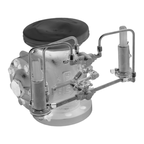
The Type 63EGLP/63EGLP-16 pilot operated pressure
relief valve is used for vapor service only. The main valve
uses a quick-change trim package for fast maintenance.
WARNING
Type 63EGLP/63EGLP-16
P1673_1
TYPE 63EGLP NPS 4 / DN 100 FLANGED VERSION
P3171
TYPE 63EGLP-16 2 MNPT VERSION
Figure 1. Type 63EGLP/63EGLP-16 Bulk Plant Relief Valve
6358EBLP_1
Figure 2. Type 6358EBLP Pilot
Advertisement
Table of Contents

Related Manuals for Emerson Fisher 63EGLP


Summary of Contents for Emerson Fisher 63EGLP
- Page 1 Fisher™ relief valves must be installed, operated and maintained in accordance with federal, state and local codes, rules and regulations and Emerson Process Management Regulator Technologies, Inc. (Emerson) instructions. P1673_1 TYPE 63EGLP NPS 4 / DN 100 FLANGED VERSION...
-
Page 2: Specifications
Type 63EGLP/63EGLP-16 Specifications Specifications for the Type 63EGLP/63EGLP-16 construction is listed on Specifications section and Tables 1 to 3. The specifications for a given construction as it originally comes from the factory are stamped on nameplates located on the main valve body. The pilot valve set pressure appears on the pilot spring case. Available Constructions Valve Plug Travel: Type 63EGLP/63EGLP-16 with two... - Page 3 3. 4x3 in. flange reducer assembly available for 3 in. flange connections. See Parts List. Note: Flow Capacity must be reduced if flange reducer assembled onto unit. Consult Emerson application engineers for flow rate reduction estimates. Table 1b. Type 63EGLP-16 Bulk Plant Relief Valves Flow Rate for 2 MNPT...
- Page 4 Type 63EGLP/63EGLP-16 ACTIVE ACTIVE INACTIVE PILOT PILOT INACTIVE PILOT PILOT SPRING VALVE DIAPHRAGM HANDLE ASSEMBLY HANDLE ASSEMBLY PILOT DISCHARGE MAIN VALVE DISCHARGE MAIN SPRING VALVE PLUG BULK STORAGE TANK BULK STORAGE TANK TYPE 63EGLP AT NORMAL CONDITION TYPE 63EGLP AT OVERPRESSURE CONDITION (BOTH MAIN VALVE AND ACTIVE PILOT ARE CLOSED) (ACTIVE PILOT DISCHARGES LOADING PRESSURE, MAIN VALVE DISCHARGES EXCESS INLET PRESSURE)
-
Page 5: Installation
Type 63EGLP/63EGLP-16 HOLLOW PASSAGE IN VALVE PLUG STEM DIAPHRAGM ASSEMBLY UPPER PORTION OF VALVE PLUG FIXED RESTRICTION LOWER PORTION TO MAIN VALVE OF VALVE PLUG DIAPHRAGM TO EXHAUST PORT EXPANDED VIEW OF THE TYPE 6358EBLP RELIEF PILOT DIAPHRAGM ASSEMBLY AND VALVE PLUG INLET PRESSURE OUTLET (EXHAUST) PRESSURE ATMOSPHERIC PRESSURE... - Page 6 Type 63EGLP/63EGLP-16 PORT A (EXHAUST) PORT C (LOADING) PORT D (CONTROL) PORT A (EXHAUST)—THE MAIN VALVE LOADING PRESSURE IS DISCHARGED TO THE MAIN VALVE OUTLET OR TO ATMOSPHERE PRESSURE. PORT C (LOADING)—A LOADING PRESSURE SIGNAL IS SENT FROM THIS PORT TO THE MAIN VALVE DIAPHRAGM CASING. PORT D (CONTROL)—THE MAIN VALVE INLET PRESSURE IS SENSED AT THIS PORT.
- Page 7 Type 63EGLP/63EGLP-16 2. For Type 63EGLP: Use the lifting sling (key 50) exhaust connection. Provide protection on a remote wrapped around outlet flange (as shipped) to lift the vent by installing a screened vent cap into the remote Type 63EGLP when installing the unit. After installing end of the vent pipe.
-
Page 8: Startup And Adjustment
Type 63EGLP/63EGLP-16 Figure 8. Type 63EGLP 3-Way Ball Valve Stem Check NOTE: TYPE 63EGLP-16 THE SAME CONSTRUCTION WITH A SMALLER HANDLE. Figure 7. Type 63EGLP with Dual Pilot-Valve Active Monitoring, Center Handle Position Startup and Adjustment The relief valve is factory set at the set-point pressure requested. -
Page 9: Valve Assembly
Type 63EGLP/63EGLP-16 Visually inspect the physical condition of the relief valve at Due to the care Emerson takes in meeting all least once a year to check if there are leaks or damage to manufacturing requirements (heat treating, dimensional the relief valve. If the relief valve or pilots show any visible tolerances, etc.), use only replacement parts... - Page 10 Type 63EGLP/63EGLP-16 are unable to completely depressurize △ CAUTION the inactive pilot, contact your local LP-Gas distributor for additional support Only apply thread sealant to Male NPT as the ball valve assembly may need to threads. Sealant applied to female pipe be replaced.
- Page 11 Type 63EGLP/63EGLP-16 To Install an Additional Pilot △ CAUTION Note Only apply thread sealant to Male NPT This section only applies to threads. Sealant applied to female pipe Type 63EGLP/63EGLP-16 assemblies connections or to compression fittings received with one pilot. If your assembly could inhibit the seal and result in a leak or has two pilots, skip to section To Change product contamination.
- Page 12 Type 63EGLP/63EGLP-16 W2772_1 W3012_1 FLIPPING THE BODY FLANGE OVER AND UNSCREWING OF CAGE FROM LIFTING THE ENTIRE TRIM PACKAGE ANCHORING IT ON THE VALVE BODY BODY FLANGE Figure 10. Replacing Trim Parts on Site Using Body as Holding Fixture Type 63EGLP/63EGLP-16 Main Valve Body 10.
-
Page 13: Parts Ordering
Type 63EGLP/63EGLP-16 1. Remove the pilots and pilot pipe nipples from the Note valve body. Remove the body flange plug (key 27) When installing the main valve Repair and the spring (key 9) and attached parts. Kit, align the body flange and valve body 2. -
Page 14: Parts List
Type 63EGLP/63EGLP-16 Parts List Main Valve Body (Figure 11) Types 6358EBLP and 6358EBHLP Pilot Valves (Figure 13) Description Part Number Main Valve Parts kit (included are keys 4, 12, Description Part Number 14, 15, 17, 20 and 21) R63EGLPX012 Pilot Body, CF8M Stainless steel 39A5972X012 Tank to Valve studs and Spring Case, Stainless steel... - Page 15 Type 63EGLP/63EGLP-16 35A3174-A 25A3169_B COMPLETE STEEL MAIN VALVE ASSEMBLY TRIM PACKAGE ASSEMBLY Figure 11. Type 63EGLP Main Valve Trim Package Type 63EGLP, NPS 4 / DN 100, CL300 RF Type 63EGLP-16, 2 MNPT Mounting Parts Mounting Parts (Figure 14) (Figure 15) Description Part Number Description...
- Page 16 Type 63EGLP/63EGLP-16 Figure 12. Type 63EGLP-16 Main Valve Assembly for 2 MNPT...
- Page 17 Type 63EGLP/63EGLP-16 48B3430 48B3431_A TYPE 6358EBLP PILOT INTERIOR VIEW TYPE 6358EBHLP PILOT INTERIOR VIEW 48B3430_A TYPE 6358EBLP PILOT WITH DIAPHRAGM LIMITER FOR 180 TO 350 psig / 12.4 TO 24.1 bar SET PRESSURE RANGE INTERIOR VIEW APPLY SEALANT (S) Figure 13. Types 6358EBLP and 6358EBHLP Pilot Assemblies...
-
Page 18: Front View
Type 63EGLP/63EGLP-16 TYPE 6358EBLP PILOT ASSEMBLY TYPE 6358EBLP PILOT ASSEMBLY FRONT VIEW ERAA03024 BACK VIEW (ALL PARTS EXCEPT PILOTS FROM TYPE 63EGX7) Figure 14. Mounting Parts Assembly for Type 63EGLP, NPS 4 / DN 100, CL300 RF... - Page 19 Type 63EGLP/63EGLP-16 TYPE 6358EBLP PILOT ASSEMBLY (6358X3) TYPE 6358EBLP PILOT ASSEMBLY (6358X3) ERAA52569_AA Figure 15. Type 63EGLP-16 for 2 MNPT...
- Page 20 D450319T012 © 2013, 2022 Emerson Process Management Regulator Technologies, Inc. All rights reserved. 10/22 The Emerson logo is a trademark and service mark of Emerson Emerson Process Management Electric Co. All other marks are the property of their prospective owners.
Need help?
Do you have a question about the Fisher 63EGLP and is the answer not in the manual?
Questions and answers