Table of Contents
Advertisement
Instruction Manual
D200138X012
Fisherr 3582 and 3582i Positioners, 582i
Electro-Pneumatic Converter, and 3583 Valve
Stem Position Transmitter
Contents
. . . . . . . . . . . . . . . . . . . . . . . . . . . . . . . . .
. . . . . . . . . . . . . . . . . . . . . . . . . . . . .
. . . . . . . . . . . . . . . . . . . . . . . . . . . . . . . . .
. . . . . . . . . . . . . . . . . . . . . . . . . . . . . . .
. . . . . . . . . . . . . . . . . . . . . . . . .
. . . . . . . . . . . . . . . . . . . . . . . . . . . . . . . . . .
Instructions for "Safe Use" and Installation
in Hazardous Areas for 582i Converter
. . . . . . . . . . . . . . . . . . . . . . . . . . . . . . . . . . . .
FM
. . . . . . . . . . . . . . . . . . . . . . . . . . . . . . . . . . . . .
. . . . . . . . . . . . . . . . . . . . . . . . . . . . . . . . . .
. . . . . . . . . . . . . . . . . . . . . . . . . . . . . . . . . .
. . . . . . . . . . . . . . . . . . . . . . . . . . . . . . . . .
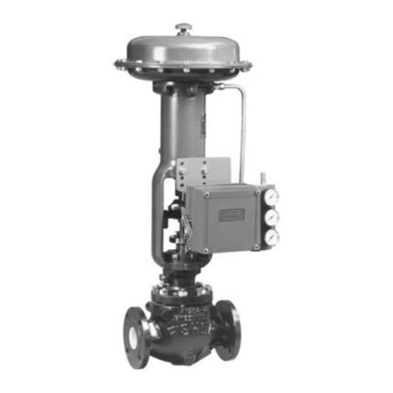
Figure 1. Typical Mounting for Fisher 3582 and 3582i Positioners and 3583 Transmitters
W5498-1
CONTROL VALVE WITH
3582 POSITIONER
www.Fisher.com
2
2
2
. . . . . . . . . . . . . . . .
6
6
7
7
. . . . . . . .
8
9
9
10
12
13
W8424
CONTROL VALVE WITH
3582i POSITIONER
. . . . . . . . . . . . . . . . . . . . . . . . . . . . . . . . . . . . . .
. . . . . . . . . . . . . . . . . . . . . . . . . .
. . . . . . . . . . . . . . . . . . . . . . . .
. . . . . . . . . . . . . . . . . . . . . . . . . . . . .
3582, 582i, and 3583
January 2013
. . . . . . . . . . . . . . . . . . . . . .
. . . . . . . . . . . . . . . . . . . . . . .
. . . . . . . . . . . . . . . . . . . . . .
. . . . . . . . . . . . . . . . . . . . . .
. . . . . . . . . . . . . . . . . .
. . . . . . . . . . . . . . . . . .
. . . . . . . . . . . . . . . . . . .
. . . . . . . . . . . . .
(continued on page 2)
W5499-1
CONTROL VALVE WITH
3583 TRANSMITTER
18
18
18
20
20
20
21
21
23
24
24
26
Advertisement
Table of Contents

Related Manuals for Emerson Fisher 3582i


Summary of Contents for Emerson Fisher 3582i
-
Page 1: Table Of Contents
Instruction Manual 3582, 582i, and 3583 D200138X012 January 2013 Fisherr 3582 and 3582i Positioners, 582i Electro‐Pneumatic Converter, and 3583 Valve Stem Position Transmitter Contents Changing Cam Position ..... . Pressure Connections . -
Page 2: Introduction
To avoid personal injury or property damage it is important to carefully read, understand, and follow all of the contents of this manual, including all safety cautions and warnings. If you have any questions about these instructions, contact your Emerson Process Management sales office before proceeding. - Page 3 Instruction Manual 3582, 582i, and 3583 D200138X012 January 2013 Table 1. Specifications for Fisher 3582 and 3582i Valve Positioners Note: Specifications for 3582 positioners include 3582i 3582A, 3582C, 3582D, 3582G, and 3582NS unless 1.4 bar (20 psig) Supply: 0.46 normal m otherwise indicated (17.2 scfh) 2.0 bar (30 psig) Supply: 0.57 normal m...
- Page 4 KGS— Korea Gas Safety Corporation bear the CE marking related to PED compliance. NEPSI— China Contact your Emerson Process Management sales However, the product may bear the CE marking to office for classification/certification specific indicate compliance with other applicable European information Community Directives.
- Page 5 Instruction Manual 3582, 582i, and 3583 D200138X012 January 2013 Table 2. Specifications for Fisher 3583 Valve Stem Position Transmitters Input Signal Operating Influence 105 mm (4.125 inches) of valve stem travel; Output signal changes 1.67 percent per bar adjustable to obtain full output signal with lesser (0.23 percent per 2 psig) change in supply pressure stem travels Operative Ambient Temperature Limits...
-
Page 6: Type Number Descriptions
The 582i electro‐pneumatic converter is a modular unit that can be installed at the factory or in the field. However, do not install a 582i converter on an existing positioner until you contact your Emerson Process Management sales office for application assistance. -
Page 7: Educational Services
Educational Services For information on available courses for 3852, 3582i and 3583, as well as a variety of other products, contact: Emerson Process Management Educational Services, Registration P.O. Box 190; 301 S. 1st Ave. Marshalltown, IA 50158‐2823... -
Page 8: Hazardous Area Classifications And Special
Special instructions are listed by approval. Note This information supplements the nameplate markings affixed to the product. Always refer to the nameplate itself to identify the appropriate certification. Contact your Emerson Process Management sales office for approval/certification information not listed here. WARNING Failure to follow these conditions of “safe use”... -
Page 9: Csa
Instruction Manual 3582, 582i, and 3583 D200138X012 January 2013 Intrinsically Safe, Explosion proof, Type n, Dust‐Ignition proof, DIV 2 No special conditions for safe use. Refer to table 4 for additional information, figure 28 for CSA loop schematics, and figure 29 for a typical CSA/FM approval nameplate. -
Page 10: Atex
Instruction Manual 3582, 582i, and 3583 January 2013 D200138X012 ATEX Standards Used for Certification EN 60079-0: 2006 EN 61241-0: 2006 EN 60079-1: 2007 EN 61241-1: 2004 EN 60079-11: 2007 EN 61241-11: 2006 EN 60079-15: 2005 Special Conditions for Safe Use Intrinsically Safe, Dust This equipment is intrinsically safe and can be used in potentially explosive atmospheres. - Page 11 Instruction Manual 3582, 582i, and 3583 D200138X012 January 2013 Table 6. Hazardous Area Classifications for Fisher 582i Converter —ATEX Certificate Certification Obtained Entity Rating Temperature Code Enclosure Rating II 1 G & D T4 (Tamb ≤ 71°C) Intrinsically Safe T5 (Tamb ≤ 62°C) Ui = 30 VDC T6 (Tamb ≤...
-
Page 12: Iecex
Instruction Manual 3582, 582i, and 3583 January 2013 D200138X012 IECEx Conditions of Certification Intrinsically Safe WARNING Substitution of components may impair intrinsic safety. -40_C ≤ Ta ≤ +71_C; T6 (Ta ≤ +47_C); T5 (Ta ≤ +62_C); T4 (Ta ≤ +71_C) Entity Parameters Ui = 30 V, li = 150 mA, Pi = 1.25 W, Ci = 0 nF, Li = 0 mH Flameproof... -
Page 13: Mounting
Instruction Manual 3582, 582i, and 3583 D200138X012 January 2013 Mounting Key numbers used in this procedure are shown in figure 2 except where indicated. 1. Figure 2 shows the various mounting parts required for mounting on Fisher actuators. Mounting parts for actuators that require spacers have the spacers (key 50) included. - Page 14 Instruction Manual 3582, 582i, and 3583 January 2013 D200138X012 2. As shown in figures 2 and 4 attach the connector arm (key 48) to the stem connector so that the connector arm extends through the yoke legs on the side of the lower mounting boss. 3.
- Page 15 Instruction Manual 3582, 582i, and 3583 D200138X012 January 2013 degrees as the actuator is stroked, and the 30‐degree index marks on the cam will be short of aligning with the case index marks. If necessary, adjust the travel pin position so that the 30‐degree marks are the same distance from the respective case index mark at each end of actuator travel.
- Page 16 Instruction Manual 3582, 582i, and 3583 January 2013 D200138X012 Figure 4. Isometric View Showing Motion Feedback Arrangement and Typical Stem Connection ACTUATOR TRAVEL PIN STEM (KEY 60) STEM CONNECTOR CONNECTOR ARM (KEY 48) CAP NUT (KEY 62) ROTARY SHAFT ARM (KEY 2) POSITIONER YOKE VALVE PLUG STEM...
- Page 17 Instruction Manual 3582, 582i, and 3583 D200138X012 January 2013 Figure 6. Rotary Shaft Arm and Case Index Marks CASE INDEX MARKS 0‐DEGREE ARM INDEX 30 DEGREES MARKS 30‐DEGREE 30 DEGREES ARM INDEX MARKS ARM AT MID‐TRAVEL POSITION ACTUATOR STEM TRAVEL INDEXES NOTES: ..MAXIMUM ROTATION FROM MID‐TRAVEL POSITION.
-
Page 18: Changing Cam Position
While use and regular maintenance of a filter that removes particles larger than 40 micrometers in diameter will suffice in most applications, check with an Emerson Process Management field office and industry instrument air quality standards for use with corrosive air or if you are unsure about the proper amount or method of air filtration or filter maintenance. - Page 19 Instruction Manual 3582, 582i, and 3583 D200138X012 January 2013 Figure 7. Typical Dimensions and Connections 141.2 139.7 246.1 (5.56) (5.50) (9.69) 119.1 57.2 182.6 (4.69) (2.25) (7.19) OF ACTUATOR 12.7 (.31) (0.50) 1/2‐14 NPT CONDUIT CONN 8.6 (.34) ∅ HOLES SPACED 17.5 (.69) 289.0 APART...
-
Page 20: Output Connection
Instruction Manual 3582, 582i, and 3583 January 2013 D200138X012 mounted on the positioner. For the 3582NS the regulator can be mounted on the mounting plate with the positioner but not on the positioner. The supply pressure should be high enough to permit setting the regulator 0.3 bar (5 psi) above the upper limit of the appropriate pressure range, for example: 1.4 bar (20 psig) for a 0.2 to 1.0 bar (3 to 15 psig) range. -
Page 21: Vent
Instruction Manual 3582, 582i, and 3583 D200138X012 January 2013 Vent WARNING Personal injury or property damage could result from fire or explosion of accumulated gas if a flammable gas is used as the supply pressure medium and the positioner/actuator is in an enclosed area. The positioner/actuator assembly does not form a gas‐tight seal, and when the assembly is enclosed, a remote vent line, adequate ventilation, and necessary safety measures should be used. - Page 22 Instruction Manual 3582, 582i, and 3583 January 2013 D200138X012 Use the 1/2‐14 NPT conduit connection on the 582i converter housing for installation of field wiring. For Class I, Division I explosion‐proof applications, install rigid metal conduit and a seal no more than 457 mm (18 inches) from the converter.
-
Page 23: Converter Installation
January 2013 582i Converter Installation Note Contact your Emerson Process Management sales office for application information before upgrading an existing 3582 valve positioner by field installation of a 582i electro‐pneumatic converter. WARNING Avoid personal injury from sudden release of process pressure. Before mounting the 582i converter: D Always wear protective clothing, gloves, and eyewear when performing any maintenance operations. -
Page 24: Operating Information
Instruction Manual 3582, 582i, and 3583 January 2013 D200138X012 When the positioner is correctly attached to the mounting plate, proceed with the installation by taking the control valve/actuator/positioner package out of service. 2. Properly vent the actuator loading pressure and the supply pressure. Disconnect the pressure tubing connections to the valve positioner. - Page 25 Instruction Manual 3582, 582i, and 3583 D200138X012 January 2013 for example, the stem will travel 50 percent with cam A, 68 percent with cam B, and 32 percent with cam C. Figure 13 shows how the flow characteristics change when using the cams with a valve that has equal percentage characteristics.
-
Page 26: Valve Stem Position Transmitter Cam Information
Instruction Manual 3582, 582i, and 3583 January 2013 D200138X012 When cam A is the operating cam, there is a linear relationship between an incremental instrument pressure change and the resultant valve stem travel. The flow characteristic is that of the control valve. Installing either cam B or C as the operating cam changes the relationship between the incremental instrument pressure change and valve stem travel, thereby modifying the valve flow characteristic. -
Page 27: Input Signal Ranges
Instruction Manual 3582, 582i, and 3583 D200138X012 January 2013 With a reverse‐acting or split‐range valve positioner, the bypass handle may be locked in the POSITIONER position so that bypass cannot be used. To lock the bypass handle in the POSITIONER position, first shut off the instrument and supply pressure to the valve positioner. -
Page 28: Changing Valve Positioner Action
Instruction Manual 3582, 582i, and 3583 January 2013 D200138X012 On some applications where the input signal span is comparatively small (as found with split‐range applications), the nozzle adjustment may not be enough to set the proper starting point. Also, some difficulty may be experienced in keeping a valve positioner from unloading when the input signal continues to increase above the split‐range. -
Page 29: Calibration Of Valve Positioner Or Valve Stem Position Transmitter
Instruction Manual 3582, 582i, and 3583 D200138X012 January 2013 1. Unhook the spring (key 38), and remove the cam bolt (key 6), cam (key 4), and spring retainer bracket (key 43). 2. Screw the locking nut (key 45) all the way onto the cam bolt. Note If the arrow stamped on the cam points toward the nozzle, output pressure increases with downward stem movement. - Page 30 Instruction Manual 3582, 582i, and 3583 January 2013 D200138X012 To level the beam, proceed as follows: Note In the following steps, if the required rotary shaft arm position cannot be attained when adjusting a pivot point, adjust one of the other pivot points slightly.
-
Page 31: Calibration
Instruction Manual 3582, 582i, and 3583 D200138X012 January 2013 Figure 16. Rotary Shaft Arm 0‐Degree and Case Index Marks, Location and Alignment CASE INDEX MARKS 0‐DEGREE ARM INDEX MARKS ARM AT MID‐TRAVEL POSITION ACTUATOR STEM TRAVEL INDEXES NOTE: ALIGN INDEX MARKS AS SHOWN FOR MID‐TRAVEL POSITION. A2452‐3 Calibration WARNING... -
Page 32: Principle Of Operation
Instruction Manual 3582, 582i, and 3583 January 2013 D200138X012 Note The positioner will fully vent or pressurize the actuator to supply pressure at the ends of actuator travel when the positioner is calibrated correctly. Failure to properly calibrate the positioner may result in reduced seat loading. Table 11. -
Page 33: 3582I Valve Positioner
The DC current input operates coils in a force balanced beam system which in turn, control bleed air through an integral nozzle/flapper arrangement. The nozzle pressure provides the pneumatic input signal pressure used by the pneumatic valve positioner. Figure 18. Schematic Illustration of Fisher 3582i Positioner 4‐20 MILLIAMPERE— INPUT SIGNAL ) -
Page 34: 3583 Valve Stem Position Transmitters
Instruction Manual 3582, 582i, and 3583 January 2013 D200138X012 3583 Valve Stem Position Transmitters 3583 (3583, 3583C) pneumatic valve stem position transmitters are mechanically linked to the valve stem in a diaphragm‐actuated, sliding‐stem control valve package. A change in the position of the valve stem changes the output pressure produced by the position transmitter. -
Page 35: Maintenance
For explosion proof applications, disconnect power before removing the converter housing cap in an explosive atmosphere. WARNING When replacing components, use only components specified by Emerson Process Management. Substitution with other components may result in the positioner or transmitter no longer meeting safety certification requirements and personal injury or property damage. -
Page 36: Changing The Range Spring
Instruction Manual 3582, 582i, and 3583 January 2013 D200138X012 In case of operational difficulties, the valve positioner or valve stem position transmitter should first be checked to see that adjustments have been properly made. All pressure lines and connections should be checked for leaks. The pneumatic relay and gaskets should also be inspected and replaced if necessary. -
Page 37: Replacing The Nozzle O-Ring
Instruction Manual 3582, 582i, and 3583 D200138X012 January 2013 1. Remove the screw (key 34G), and lift out the bypass handle or manifold. 2. Remove the gasket. 3. Apply lubricant (key 94) to both sides of the replacement gasket when used with the bypass assembly of 3582 valve positioners. -
Page 38: Adjusting The Flapper Pivot
The I/P module should never be disassembled because the magnetism in the coils will decrease permanently. If troubleshooting or alignment attempts indicate a faulty I/P module, replace the module or return the converter to your Emerson Process Management sales office for repair. -
Page 39: Reassembling The 582I Converter
Instruction Manual 3582, 582i, and 3583 D200138X012 January 2013 Note To check the operation of the I/P module, remove the pipe plug (key 12), and connect a pressure gauge. Provide a 1.4 bar (20 psig) supply pressure to the converter. With a 4 mA signal the pressure output should read 0.16 to 0.24 bar (2.3 to 3.5 psig). With a 20 mA input signal the pressure output should read 0.96 to 1.07 bar (14.0 to 15.5 psig). -
Page 40: Parts Ordering
Use only genuine Fisher replacement parts. Components that are not supplied by Emerson Process Management should not, under any circumstances, be used in any Fisher instrument. Use of components not supplied by Emerson Process Management may void your warranty, might adversely affect the performance of the instrument, and could cause personal injury or property damage. -
Page 41: Parts List
Note Parts 19A through 19L are shown in figure 20. Note Part numbers are shown for recommended spares only. For part numbers not shown, contact your Emerson Process Management sales office. 19A Adjustment Arm, pl steel 19B Flapper, SST 19C Machine Screw, pl steel (2 req'd) - Page 42 Instruction Manual 3582, 582i, and 3583 January 2013 D200138X012 Figure 21. Fisher 3582 and 3583 Positioners and Transmitters Assembly Drawing SECTION B‐B TYPICAL CAM (KEY 4) SECTION A‐A NOTE: APPLY A GOOD‐QUALITY THREAD LOCKING COMPOUND TO THE THREAD OF THE NOZZLE ADAPTOR (KEY 3). SECTION C‐C 41B8558‐E...
- Page 43 Instruction Manual 3582, 582i, and 3583 D200138X012 January 2013 Figure 22. Nozzle Sub‐Assembly Figure 23. 83L Relay UNITS STAMPED WITH AN H INDICATE HIGH TEMPERATURE CONSTRUCTION 12A7441‐C 32B0255‐B Description Part Number Description Part Number 36* Output Gauge, Triple Scale Flapper Assembly Retainer, SST 3582, 3582G, 3583 Self Tapping Screw, pl steel (2 req'd) 0-30 psig/0-0.2 MPa/0-2 bar...
- Page 44 Instruction Manual 3582, 582i, and 3583 D200138X012 January 2013 Description Part Number Description Part Number Test Connection 3582C, 3582D (3 req'd) 3583C (2 req'd) Adhesive, Loctite Retaining Compound 3582NS (3 req'd) (not furnished with positioner) Locking Nut, aluminum 103* O‐Ring, nitrile, (not shown) used with integrally Locking Sleeve, aluminum mounted 67CFR filter regulator 1E591406992...
- Page 45 Instruction Manual 3582, 582i, and 3583 D200138X012 January 2013 For Units With Bypass (figure 24) Description Part Number 34A Bypass Block, aluminum Note 34B* Groove‐Pin, pl steel (not shown) (4 req'd) 1L942828992 Bypass block assembly (key 34) and parts are listed below. Non‐bypass block assembly (also key 34) and parts are listed following the bypass 34C* Bypass Gasket block assembly and parts.
- Page 46 Instruction Manual 3582, 582i, and 3583 D200138X012 January 2013 For Units Without Bypass (figure 25) Description Part Number 34A Bypass Block, aluminum Description 34C* Gasket Std. const., chloroprene 1V606204132 Hi‐temp. const. 1V6062X0012 Non‐Bypass Block Assembly 3582NS, EPDM 17B4780X012 Std. const. 34D Manifold 3582A, 3582C, 3582G 3582, std.
- Page 47 Instruction Manual 3582, 582i, and 3583 D200138X012 January 2013 Description Part Number Description Part Number 582i (figure 26) 14* Supply Gauge, Dual Scale 0-30 psig/0-2 kg/cm 11B4040X042 I/P Module 0-60 psig/0-4 kg/cm 11B4040X052 Housing 14* Supply Gauge, Triple Scale 1/2‐14 NPT conduit connection 0-30 psig/0-0.2 MPa/0-2 bar 11B4040X012 Cap, aluminum...
- Page 48 Sizes 80 & 87 (2 req'd) Size 100 (2 req'd) Note 657‐4 (2 req'd) Contact your Emerson Process Management sales office for mounting FS w/o side‐mtd. h'wheel Numbers. Size 70 Part numbers are shown for recommended spares only. For part w/side‐mtd.
- Page 49 Instruction Manual 3582, 582i, and 3583 D200138X012 January 2013 Description Description Part Number Spacer, steel Hex Nut 657 (continued) 657NS or 667NS w/side‐mtd. h'wheel Size 80 (none req'd) Sizes 34, 50, & 60 (2 req'd) All other types and sizes (2 req'd) Size 40 (none req'd) Lockwasher Size 45 &...
- Page 50 Instruction Manual 3582, 582i, and 3583 January 2013 D200138X012 Description Description Spacer, steel Cap Screw, pl steel (2 req'd) 657 or 667 w/ side‐mtd. h'wheel 657 w/side‐mtd. h'wheel (continued) Size 70 & 87 Size 100 up to 51 mm (2 inch) travel (2 req'd) 52 to 76 mm (2.0625 to 3 inch) travel (2 req'd) up to 64 mm (2.5 inch) travel 65 to 102 mm (2.5625 to 4 inch) travel...
- Page 51 Travel Pin, SST, all sizes (2 req'd) 1U909646332 Note Pin Holder, SST, all sizes (2 req'd) Contact your Emerson Process Management sales office for mounting FS Cap Nut, SST, all sizes (2 req'd) Numbers. Part numbers are shown for recommended spares only. For part...
- Page 52 Instruction Manual 3582, 582i, and 3583 January 2013 D200138X012 Description Description Cap Screw, pl steel Cap Screw, pl steel (4 req'd) (continued) 657 657 or 667 w/side‐mtd. h'wheel (continued) Sizes 30 thru 60, & 80 Size 87 Size 100 up to 76 mm (3 inch) travel (none req'd) up to 64 mm (25 inch) travel 78 to 102 mm (3.0625 to 4 inch) travel 65 to 102 mm (2.5625 to 4 inch) travel...
- Page 53 For integrally mounted 67CFR Note For separately mounted 67CFR Part numbers are shown for recommended spares only. For part numbers not shown, contact your Emerson Process Management sales Cap Screw, pl steel (8 req'd) office. Cap Screw, pl steel (2 req'd)
-
Page 54: Loop Schematics/Nameplates
Loop Schematics/Nameplates This section includes loop schematics required for wiring of intrinsically safe installations. It also contains typical approvals nameplates. If you have any questions, contact your Emerson Process Management sales office. Figure 28. CSA Loop Schematic for Fisher 582i Converter NOTES: 1. BARRIERS MUST BE CSA CERTIFIED WITH ENTITY PARAMETERS... - Page 55 Instruction Manual 3582, 582i, and 3583 D200138X012 January 2013 Figure 29. Typical CSA / FM Approval Nameplate for Fisher 582i Converter Figure 30. FM Loop Schematic for Fisher 582i Converter WARNING FOR INTRINSICALLY SAFE APPLICATIONS: THE APPARATUS ENCLOSURE CONTAINS ALUMINUM AND IS CONSIDERED TO CONSTITUTE A POTENTIAL RISK OF IGNTION BY IMPACT AND FRICTION.
- Page 56 Fisher and FlowScanner are marks owned by one of the companies in the Emerson Process Management business unit of Emerson Electric Co. Emerson Process Management, Emerson, and the Emerson logo are trademarks and service marks of Emerson Electric Co. All other marks are the property of their respective owners.
Need help?
Do you have a question about the Fisher 3582i and is the answer not in the manual?
Questions and answers