Table of Contents
Advertisement
Quick Links
Advertisement
Table of Contents

Related Manuals for ABB M4M 20


Summary of Contents for ABB M4M 20
- Page 1 Network analyzer M4M 20 M4M 20-M User manual...
-
Page 3: Table Of Contents
M4M 20 NETWORK ANALYZER USER MANUAL Table of Contents 1.General information....................5 1.1.Use and storage of the manual ................5 1.2.Copyright ........................5 1.3.Liability disclaimer ....................5 1.4.General safety warnings ..................5 1.5.Cyber Security Disclaimer ..................6 2.Packaging contents ....................7 3.Technical characteristics ..................8 3.1.Description of the device ..................8 3.2.Product Marking ......................8... - Page 4 M4M 20 NETWORK ANALYZER USER MANUAL 7.7.Lock MID version ....................35 8.Configuration ......................36 8.1.Unit...........................36 8.2.Installation ......................41 8.3.Inputs / Outputs ....................43 8.4.Alarms ........................46 8.5.Communication ....................48 8.6.Other settings .......................51 9.Data Reading ....................... 53 9.1.Realtime ......................... 54 9.2.Energy ........................55 9.3.Power Quality ....................... 56 9.4.Average ........................57...
-
Page 5: General Information
The information contained in this document is subject to change without notice and cannot be considered as an obligation by ABB S.p.A. ABB S.p.A. is not liable for any errors that may appear in this document. ABB S.p.A. is not liable under any circumstances for any direct, indirect, special, incidental or consequential damage of any kind that may arise from using this document. -
Page 6: Cyber Security Disclaimer
ABB S.p.A. and its affiliates are not liable for damages and/ or losses related to such security breaches, unauthorized access, interference, intrusion, leakage and/or theft of data or information. -
Page 7: Packaging Contents
MODBUS M4M 20-M MODBUS M4M 20 ETHERNET M4M 20-M ETHERNET M4M 20 PROFIBUS M4M 20 I/O M4M 20 BACNET M4M 20 ROGOWSKI Please notice that terminals for current input on M4M 20 Rogowski are pre-wired on ABB’s R4M Rogowski coils... -
Page 8: Technical Characteristics
M4M 20 NETWORK ANALYZER USER MANUAL 3.Technical characteristics 3.1.Description of the device M4M 20 is ABB’s network analyzer range that provides complete and accurate electrical pa-rameters monitoring and basic power quality analysis. Equipped with graphic color display for advanced visualization of the measured parameters and Bluetooth module for smart commissioning. -
Page 9: Main Functionalities
M4M 20 NETWORK ANALYZER USER MANUAL 3.3.Main functionalities Real-time TRMS current • TRMS Voltage • Frequency • Active, Reactive and Apparent Power • Power Factor • Operating timer, countdown timer • Energy Active, Reactive and Apparent Energy • 4 quadrant Energy (Import/Export) •... -
Page 10: Versions
M4M 20 NETWORK ANALYZER USER MANUAL 3.4.Versions Product Name Communication protocol M4M 20 2 Digital Outputs Bluetooth M4M 20 MODBUS 2 Digital Outputs Modbus RTU, Bluetooth M4M 20-M MODBUS 2 Digital Outputs Modbus RTU, Bluetooth M4M 20 ETHERNET 2 Digital Outputs... -
Page 11: Technical Data
M4M 20 NETWORK ANALYZER USER MANUAL 3.6.Technical data Auxiliary power supply Voltage range 48 to 240 VAC/VDC ±15% Frequency [Hz] 50/60 Hz ±5% Power consumption [VA] 10 VA max Installation category CAT III 300V class per IEC 61010-1 edition 3... - Page 12 Max voltage for OFF state on input 20 VAC/DC Min voltage for ON state on input 45 VAC/DC M4M 20-M (MID): The Digital Output 1 of the M4M 20-M Modbus and M4M 20-M Ethernet is assigned as Pulse Output, associated to the active energy measured value.
- Page 13 M4M 20 NETWORK ANALYZER USER MANUAL Analogue Output Programmable electrical parameters Span [0 - 20 mA or 4 - 20 mA] Load Typical 250 Ohm, max 500 Ohm Mechanical characteristics 96 mm x 96 mm x 77,5 mm Overall dimensions...
- Page 14 5 pushbuttons Display type Graphic color display Display dimensions 70 x 52 mm (3.5") Communication protocol M4M 20 Modbus, M4M 20 I/O, M4M 20 Rogowski, M4M Modbus RTU 20-M Modbus Communication interface RS485 with optical isolation Baud rate 9.6, 19.2, 38.4, 57.6, 115.2 kbps...
- Page 15 M4M 20 NETWORK ANALYZER USER MANUAL Technical data for M4M 20-M according to the Measuring Directive 2014/32/EU EN 50470-1 MID standards EN 50470-3 3Ph/4W/3CT Voltage measurement 3Ph/3W/2CT (type of network and rated voltage) 1Ph/2W/1CT 3 x 230 (400)...3 x 400 (690) V...
-
Page 16: Measurement Method
The ABB M4Ms use the vector registration method for computation of energy. 4.1.Vector registration method In the vector registration method the instantaneous energy consumption of the measuring elements (the three phases in 3-phase 4-wire metering) is summed up to the total register. -
Page 17: Installation
M4M 20 NETWORK ANALYZER USER MANUAL 5.Installation 5.1.Assembly M4M 20 Sealing of terminal block for M4M 20-M (MID) M4M 20-M (MID): In order to ensure antitampering for MID directive, sealing of terminal block is mandatory click Sealing... -
Page 18: Disassembly M4M 20
M4M 20 NETWORK ANALYZER USER MANUAL 5.2.Disassembly M4M 20 5.3.Disassembly M4M 20: In order to remove the terminal block, please use a screwdriver in the dedicated area and turn it. Please notice that if seal is broken, tampering of M4M for MID will happen! -
Page 19: Wiring Diagrams
M4M 20 NETWORK ANALYZER USER MANUAL 5.4.Wiring diagrams The operations to carry out for the correct connection of the device, based on thetype of electric line available, are described in this section. The installation and the cabling of the device must be carried out by qualified personnel. - Page 20 M4M 20 NETWORK ANALYZER USER MANUAL • M4M 20 ETHERNET connection M4M 20-M ETHERNET connection • M4M 20 PROFIBUS connection • M4M 20 I/O connection • M4M 20 ROGOWSKI connection • M4M 20 BACNET connection...
- Page 21 According to the type of network that has been chosen, the parameters visualized on the device HMI change. Below the wiring diagrams for M4M 20 working with CT .../5A or .../1A (M4M 20, M4M 20 Modbus, M4M 20 Ethernet, M4M 20 I/O, M4M 20 Profibus, M4M 20 Bacnet, M4M 20-M Modbus, M4M 20-M Ethernet) are shown: •...
- Page 22 • 3-phase 3-wire 3-CTs + 3VTs TV3 TV2 TV1 M4M 20-M (MID): In order to ensure antitampering for MID directive, only MID compliant wiring have to be selected and sealing of terminal block is mandatory. Wiring diagrams - M4M 20 Rogowski Below the wiring diagrams for M4M 20 working with Rogowski coils (M4M 20 Rogowski) are shown: •...
- Page 23 M4M 20 NETWORK ANALYZER USER MANUAL • 3-phase 3-wire network with 1RogCT IR1 IR2 IR3 L1 L2 L3 N • 3-phase 3-wire network with 3RogCTs IR1 IR2 IR3 L1 L2 L3 N • 3-phase 3-wire network with 2RogCTs IR1 IR2 IR3 L1 L2 L3 N •...
- Page 24 I/O5 I/O6 COM A: V aux 48 V a.c./d.c. 100mA B: External relay • Programmable I/O: Pulse output (available only on M4M 20 I/O). Example of wiring for I/O5 as pulse output COM is common for all Digital outputs: I/O5 I/O6 COM A: V aux 48 V a.c./d.c.
-
Page 25: Access To Device
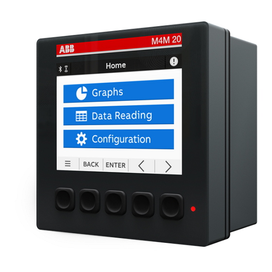
M4M 20 NETWORK ANALYZER USER MANUAL 6.Access to device 6.1.Homepage The device menu is divided into three sections. Graphs Data Reading Configuration Menu Description Graphs Graphical representation of the main parameters. Data reading Values of the main parameters. Configuration Setup of the device. -
Page 26: Navigation Symbols
M4M 20 NETWORK ANALYZER USER MANUAL 6.2.Navigation symbols Symbol Description Shortcut key with 3 sections: Notifications, Favourite page and Home. BACK Return to the previous page. ENTER Confirm the selection. Increase or decrease the value. Keeping pressed will increase the speed of the number variation. -
Page 27: Overview Of Menu Displays
M4M 20 NETWORK ANALYZER USER MANUAL 6.4.Overview of menu displays Each section of the device contains different menus and submenus as per below tables: → Graphs Menu Description Bargraphs for voltage (L-N, L-L), current, power (active, reactive, Realtime Graphs apparent). -
Page 28: Data Entry
M4M 20 NETWORK ANALYZER USER MANUAL 6.5.Data entry For the configuration it is possible either to choose from a list of values or to manually enter a value. List of values 1. Use to scroll the list on of values or fields. -
Page 29: Favourite Page
It is possible set a page as a Favourite page, that is then easily accessible by clicking the Favourite key. Setting - Favourite page M4M 20-M (MID): It is not possible to set a Favourite page, after stand-by time the menu go back to a meter summary screen with active import and export energy. -
Page 30: First Commissioning
The password can be changed in any moment in Configurations -> Unit -> Modify password (please refer to chapter “8.1.Unit”). M4M 20-M (MID): It is not possible to disable password. Password only protects non-critical configurations. Critical configurations are protected by Lock (please refer to chapter “7.7.Lock MID... -
Page 31: Date And Time
Configure the current date with format YYYY/MM/DD. Set time Configure the current time. When M4M 20 is turned off, the date and time are reset. After turning on the M4M 20 network analyzer, please configure date and time. 7.4.Type of network In order to configure the type of network it is needed to choose one of the available options according to the installation conditions. -
Page 32: Ct Ratio
M4M is capable to measure current only via indirect connection by means of current transformers CTs .../5A or .../1A (M4M 20, M4M 20 Modbus, M4M 20 Ethernet, M4M 20 I/O, M4M 20 Profibus, M4M 20 Bacnet, M4M 20-M Modbus, M4M 20-M Ethernet) , or Rogowski coils (M4M 20 Rogowski).. - Page 33 3. Insert a new value of the transformation ratio. Enter the password if necessary. Please notice that if M4M 20 Rogowski is being used, no CT ratio has to be set for Rogowski coils. Primary of CT has to be higher than the secondary.
-
Page 34: Vt Ratio
M4M 20 NETWORK ANALYZER USER MANUAL 7.6.VT ratio M4M is capable to measure voltage via direct connection up to 400 VL-N (690V L-L), or via indirect connection by means of voltage transformers. In order to configure the voltage transformer ratio it is needed to enter manually the values of both primary and secondary. -
Page 35: Lock Mid Version
At the end of the “7.First commissioning” phase the lock operation is required. It can be set once and the user cannot reset the lock state. M4M 20-M will not count any MID energy until it is locked. M4M 20-M (MID) only Following parameters, set during first commissioning phase, cannot be modified after the lock operation. -
Page 36: Configuration
M4M 20 NETWORK ANALYZER USER MANUAL 8.Configuration In order to change any configuration of the device, it is mandatory to enter the password. The password is valid as soon as the user remains in the Configuration section and for max. 10 minutes. After quitting the Configuration section, it is needed to enter again the password. - Page 37 M4M 20 NETWORK ANALYZER USER MANUAL Modify password menu In order to modify the password: → → → Unit Modify Password 1. Enter the current password. In order to select each numerical character, it is necessary to 2. Confirm the selection of all numerical...
- Page 38 It is highly recommended to update the firmware to the latest version for security and functionality reasons. Please check the ABB website and download the latest version of the firmware. In order to update the FW to the latest version (via Modbus RTU or Modbus TCP/IP) it is necessary to use...
- Page 39 M4M 20 NETWORK ANALYZER USER MANUAL Date/Time menu During the first commissioning, it is highly recommended to configure the date and time on the network analyzer (please refer to chapter “7.3.Date and time”). Brightness menu In this menu it is possible to modify the display brightness during normal operation conditions.
- Page 40 M4M 20 NETWORK ANALYZER USER MANUAL Audit log menu The Audit Log stores an event after an attempt has been made to upgrade the firmware and/or CT ratio, VT ratio or Type of network is modified. → → → Unit...
-
Page 41: Installation
Set the source for the frontal LED. M4M 20-M (MID): For MID directive, it is only possible to configure these parameters before the Lock is completed. After the lock operation, these configurations cannot be modified in order to avoid antitampering. - Page 42 M4M 20 NETWORK ANALYZER USER MANUAL CT ratio menu During the first commissioning, it is highly recommended to configure the CT ratio (please refer to chapter “7.5.CT ratio”). → → → Installation CT ratio Installation CT ratio VT ratio Type of network...
-
Page 43: Inputs / Outputs
Slot 2 Each programmable I/O slot con be configured as follow: Digital Output function: Alarm output. Communication output. Pulse output. Output ON. Output OFF. M4M 20-M (MID): For MID directive, output 1 is assigned as pulse output for active energy. - Page 44 M4M 20 NETWORK ANALYZER USER MANUAL Digital Output Each programmable I/O can be configured as Alarm output, Communication output, Pulse output, Output ON or Output OFF. Selecting Alarm output, the output can be associated to an alarm. Please note that it is mandatory to set up an alarm prior to setting an output as Alarm output.
- Page 45 BTU, L, m^3, MCF, lbs, kg, klbs, Therm. Analog output Slots 5 and 6 of the I/O menu for M4M 20 I/O contain analog outputs that can be used to associate a measured parameter to a current output value. It is possible to define the parameter to be associated to the analogue output, as well as minimum and maximum measured values to be linked to the output span.
-
Page 46: Alarms
M4M 20 NETWORK ANALYZER USER MANUAL 8.4.Alarms In this section it is possible to configure the single alarms, allowing to monitor certain value selected from a list of parameters. → → Alarms When specific conditions are met, alarms is turned on or off. Triggering of alarms can be registered in the devices notifications log, in the alarms section. - Page 47 M4M 20 NETWORK ANALYZER USER MANUAL In order to set an alarm, it is needed to define the parameter associated to the alarm, the alarm type (cross up over threshold, or cross down under threshold), the threshold value for the parameter, the activation delay and the hysteresis for the turn off threshold.
-
Page 48: Communication
M4M 20 NETWORK ANALYZER USER MANUAL 8.5.Communication → → Communication Communication menu allow to set all the parameters related to the communication protocol available for a specific product version. The embedded communication protocol varies according to the different product versions. Please refer to “3.3. Versions” for the details on the embedded communication protocols. - Page 49 EPIC to pair the device MODBUS RTU (M4M 20 Modbus, M4M 20 I/O, M4M 20 Rogowski, M4M 20-M Modbus product versions) This section is available on all the M4M 20 product versions with Modbus RTU embedded communication. → → Communication → Modbus RTU...
- Page 50 M4M 20 NETWORK ANALYZER USER MANUAL PROFIBUS (M4M 20 Profibus product version) This section is available on M4M 20 Profibus with Profibus DP-V0 embedded communication. → → Communication → Profibus Menu Description Address From 1 to 126. If DHCP is disabled, the values of above configurations (IP address, subnet mask, gateway, TCP port) are the default ones.
-
Page 51: Other Settings
M4M 20 NETWORK ANALYZER USER MANUAL 8.6.Other settings In this menu it is possible to configure the time interval for average values calculation, timers settings, energy conversion parameters. → → Other settings Other settings Average Timers Energy conversion Menu Description Average Configuration of time interval for Average values. - Page 52 M4M 20 NETWORK ANALYZER USER MANUAL Timers menu In this menu it is possible to configure the count-down timer, used for maintenance notification, and the timers reset. For the data reading of timers values please refer to chapter “9.10.Timers”. →...
-
Page 53: Data Reading
M4M 20 NETWORK ANALYZER USER MANUAL 9.Data Reading Data reading section allows to visualize all the parameters measured by M4M. → Data Reading Data Reading Realtime Energy Power Quality Average Press to return to the home page. BACK... -
Page 54: Realtime
M4M 20 NETWORK ANALYZER USER MANUAL 9.1.Realtime → → Realtime Data Reading Realtime measurement Realtime measurement Realtime measurement Realtime measurement Summary Line-Neutral voltage Line-Line voltage Current 399.11 V 2.936 kA 399.11 V 399.11 V U 3P 399.87 v 3.455 kA 230.05 v... -
Page 55: Energy
M4M 20 NETWORK ANALYZER USER MANUAL 9.2.Energy → → Energy Data Reading Energy Energy Energy Energy Active Energy - Import Active Energy - Import Reactive Energy - Import Apparent Energy - Import Active Energy - Export 1512.7 510.56 1596.54 356.23... -
Page 56: Power Quality
M4M 20 NETWORK ANALYZER USER MANUAL 9.3.Power Quality → → Power quality Data Reading Power Quality Power Quality Power Quality Power Quality THD Line-Neutral Voltage THD Line-Line Voltage THD Current Unbalances N 289.0 % 42.1 27.4 11.0 42.2 27.3 11.1 42.2... -
Page 57: Average
M4M 20 NETWORK ANALYZER USER MANUAL 9.4.Average → → Average Data Reading Average Average Average Average Line-Neutral Voltage Line-Line Voltage Current Current 228.15 395.16 954.22 115.41 229.32 397.19 841.64 227.26 393.62 985.39 Average Average Average Active Power Reactive Power Apparent Power 2.419 kW... -
Page 58: Min Value
M4M 20 NETWORK ANALYZER USER MANUAL 9.5.Min Value → → Min Value Data Reading Min Value Min Value Min Value Min Value Line-Neutral voltage Line-Line voltage Current Current 2.422 0.238 5.122 2. 247 2.527 0.550 4.203 1.989 0.643 5.237 Min Value... -
Page 59: Max Value
M4M 20 NETWORK ANALYZER USER MANUAL 9.6.Max Value → → Max Value Data Reading Max Value Max Value Max Value Max Value Line-Neutral voltage Line-Line voltage Current Current 0.941 230.05 v 399.87 v 3.120 231.14 v 398.73 v 1.951 228.68 v 397.45 v... -
Page 60: I/O
M4M 20 NETWORK ANALYZER USER MANUAL 9.7.I/O The number and type of I/O on the M4M network analyzer varies according to the different product versions. Please refer to the table in “3.4.Versions” for the detail of I/O types per each M4M. - Page 61 M4M 20 NETWORK ANALYZER USER MANUAL → → → Notifications Data Reading Notifications Alarm 2 Firmware CRC Persistent storage Alarm 1 Symbol Description Alarms Warnings Errors When one of the notifications is selected, the timestamp of the notification will be shown, indicating date and time of the alarm, warning or error.
- Page 62 M4M 20 NETWORK ANALYZER USER MANUAL Warnings → → → Notifications Warnings Data Reading Notifications Warnings l1 missing V1 missing l1 missing l1 missing If one of the warnings is selected, timestamp (Day, Hour) will be shown. Day format is YYYY:MM:DD, time format is hh:mm:ss.
-
Page 63: Power Outages
M4M 20 NETWORK ANALYZER USER MANUAL Errors → → → Notifications Errors Data Reading Notifications Errors Firmware CRC Persistent storage Below the list of possible errors: • Audit log error • Firmware CRC error • Persistent storage error • RAM memory CRC error •... -
Page 64: Timers
M4M 20 NETWORK ANALYZER USER MANUAL 9.10.Timers → → Timers Data Reading Timers Up counter 0 00:04 Down Counter 364 23:55 Menu Description Up counter Represents the timer count up of the device lifetime since the power up. Down counter... -
Page 65: Graphs
M4M 20 NETWORK ANALYZER USER MANUAL 10.Graphs In the Graphs section it is possible to visualize the main realtime parameters measured by M4M as bargraphs. Bargraphs show in an intuitive way the realtime values of voltage, current and power. The graphs are automatically scaled according to the values that are measured in realtime. -
Page 66: Maintenance
M4M 20 NETWORK ANALYZER USER MANUAL 11.Maintenance This product contains no parts that can be repaired or exchanged. A broken meter must be replaced. If you need assistance please contact ABB. Do not open the meter case and do not attempt to repair any component. Opening the meter will void... - Page 67 ......................................................................................................................................................................................................................................................................................................................................................................................................................................................................................................................................................................................................................................................................................................................................................................................................................................................................................................................................................................................................................................................................................................................................................................................................................................................................................................................................................................................................................................................................................................................................................................................................................................................................................................
- Page 68 ABB S.p.A Electrification business Viale dell’Industria, 18 20009 Vittuone (MI) Italy new.abb.com/low-voltage...
Need help?
Do you have a question about the M4M 20 and is the answer not in the manual?
Questions and answers