Table of Contents
Advertisement
Advertisement
Table of Contents

Related Manuals for Moore Industries TIY


Summary of Contents for Moore Industries TIY
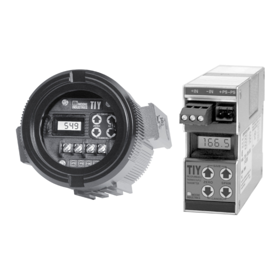
- Page 1 May 2016 Programmable Isolated 140-715-00G Thermocouple Transmitter...
-
Page 2: Table Of Contents
Specifications ....................... Ordering Information ....................Options ........................TIY Model Numbers ..................... Calibration ..........................Setting the Configuration Jumpers ................Calculating the TIY's Accuracy .................. LCD Readings ......................Standard and Quick Ranging ..................Standard Ranging ......................... 12 Quick Ranging ..........................14 Installation ........................... -
Page 3: Introduction
Several functions of the TIY are configured with calibrate, install, operate, maintain, and troubleshoot solderless jumpers. Each of these jumpers is ac- the TIY. It includes a brief unit description, a table cessible without disassembling the unit. The jump- of performance and operational specifications, and er-selectable features include: an explanation of Moore Industries’... -
Page 4: Specifications
Programmable Isolated Thermocouple Transmitter Specifications Performance Performance Output Accuracy: Isolation: 500Vrms Adjustments Zero and Span: (continued) galvanic Membrane push ±0.05% of span (maximum input-to-output isolation between input and buttons. Span error is the sum of the output terminals changes within an input, output and RFI/EMI protection: When input range (see... -
Page 5: Ordering Information
(i.e. BH2NGP) See BH and SB Datasheets for additional information. Options The TIY is available with the following options: CE Option – (HP housing only) - CE approval. SP1 Option – Temperature range for J- and T-type thermocouples (replaces N1 and N2 Range Codes) DD Option –... - Page 6 Notes: 1. The TIY output will limit at values which are 5% of maximum span lower than this value and will then display "–LO–". 2. The TIY output will not display values which are 10% of maximum span greater than this value. When exceeded, the display reads "–HI–".
-
Page 7: Tiy Model Numbers
Notes: 1. The TIY output will limit at values which are 5% of maximum span lower than this value and will then display "–LO–". 2. The TIY output will not display values which are 10% of maximum span greater than this value. When exceeded, the display reads "–HI–". -
Page 8: Setting The Configuration Jumpers
TIY Jumpers for DIN-style units are accessed by remov- operation in the safety of a testing environment, ing the small, L-shaped panel from the upper right- separate from the intended process or application. - Page 9 Programmable Isolated Thermocouple Transmitter Table 3. Jumper Settings for J301-J305 Jumper Setting Result STORED RJC Activated J301 RJC Inactive INSTALLED STORED Fahrenheit J302 INSTALLED Celcius STORED Upscale J303 INSTALLED Downscale STORED Linearization J304 INSTALLED No Linearization Standard Ranging STORED J305 INSTALLED Quick Ranging Table 4.
-
Page 10: Calculating The Tiy's Accuracy
J303 – Burnout Calculating the TIY’s Accuracy Stored – Upscale Burnout The output accuracy of the TIY is ±0.05% of span. Installed – Downscale Burnout Accuracy improves for wider spans, and degrades for This jumper determines the reaction of the TIY narrower spans. -
Page 11: Lcd Readings
*Error increases as span decreases LCD Readings Standard and Quick Ranging The LCD on the TIY displays the input readings in Ranging is a method of field calibration. The TIY degrees Celsius, degrees Fahrenheit, or millivolts. features two methods of ranging: Standard and Quick. -
Page 12: Standard Ranging
Standard ranging is used to set the zero- and Standard Ranging requires an input source, dc power 100-percent output settings of the TIY based on user- source, and an output meter. Table 6 lists the calibra- selected input values. The input values are simulated tion equipment. - Page 13 (See Table 4). and load resistor). This indicates that the zero value was captured successfully. 2. Connect the TIY as shown in Figure 2. Repeat steps 5-7 until the reading is 20 mA. 3. To view the current zero setting, press and 8.
-
Page 14: Quick Ranging
+PS and –PS terminals the meter. of the TIY is all that is required to perform Quick Ranging. The push buttons are used to set zero and span values. The user-selected values are displayed on the unit’s LCD. - Page 15 1. Set Range and Gain/Offset Jumpers for the J305 (See Figure 1 and Table 3). input type (See Table 4). 2. Apply DC power to the TIY as shown in 5. Set zero shown on LCD to desired setting Figure 3.
- Page 16 Thermocouple Transmitter Note: 6. Press and hold either SPAN push button to The TIY will take a moment to store the display the span (full scale) value. new value and reset itself. It will return to the operate mode and display the currently applied input value.
-
Page 17: Installation
The DIN-style Housing. Figure 5 is an outline The TIY is available in an HP- or DIN-style housing. d i m e n s i o n a l d r aw i n g o f t h e D I N - s t y l e T I Y. -
Page 18: Making The Electrical Connections
The maximum length of un-shielded input and output signal wiring should be 2 inches. When the input to the TIY is a thermocouple (T/C), thermocouple wire must be used for the input Note: Some of Moore Industries’ instruments can be connections. -
Page 19: Operation
The LCD Operation During normal operation, the LCD typically displays Operating the TIY is limited to viewing the LCD for the applied input value. As the input changes, the input values, zero or span reading, or problem codes; readout of the LCD changes accordingly. -
Page 20: Maintenance
When you call, please have: To perform a thorough calibration of the TIY, the unit must be removed from the system and checked out • The model number of the unit in question. - Page 21 This page contains the installation diagram for the for units that are to operate in areas requiring TIY carrying the intrinsically safe option. It also intrinsically safe instrumentation. includes guidelines for setting up zener barriers necessary in these types of applications.
- Page 22 4. Ship the equipment to the Moore Industries location nearest you. The returned equipment will be inspected and tested at the factory. A Moore Industries rep- resentative will contact the person designated on your documentation if more information is needed.
Need help?
Do you have a question about the TIY and is the answer not in the manual?
Questions and answers