
Related Manuals for Moore Industries IPT2


Summary of Contents for Moore Industries IPT2
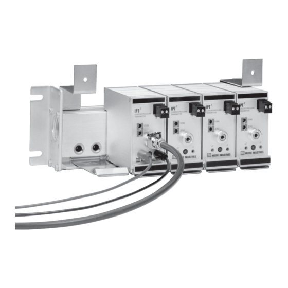
- Page 1 July 2016 Current-to-Pressure 170-730-00G (I/P) Transmitter All product names are registered trademarks of their respective companies.
-
Page 2: Table Of Contents
Table of Contents Introduction ......................3 The IPT ......................3 Specifi cations ....................3 Ordering Information ..................4 Instrument Air and Filtration Information ............5 Application Information ..................Calibration ......................7 Adjustments .........................7 Calibration Equipment ......................7 Test Jacks ..........................8 Calibration Setup........................8 Calibration Procedure ......................8 Installation ...................... -
Page 3: Introduction
The model number for the IPT is located on a label mounting rails or onto a Moore Industries RIR or SIR. on the side of the unit. Because of the low dynamic mass of the transducer Serial Number. Moore Industries maintains a element, the unit can be mounted in any position and complete history on every unit it sells and services. -
Page 4: Ordering Information
Bar) higher than output pressure. (40psi max) When ordering, specify: Unit / Input / Output / Supply Pressure / Options [Housing] Model number example: IPT2 / 4-20MA / 3-15PSIG / 20PSI / –FA1 [DIN] Table 1. Description of access designation options. (See Figure 4) LED &... -
Page 5: Instrument Air And Filtration Information
Instrument Air and Suffi cient water must be removed to lower the dew point of the air to a temperature below ambient. The Filtration Information dew point (at line pressure) is expressed as the tem- perature at which any moisture in the system begins to condense. -
Page 6: Application Information
Application Information The use of coalescing fi lters with retention of 0.01 micron particles and droplets is recommended; Any approach to providing good instrument air they remove all undesirable traces of oil and water quality should evaluate the worst case air fl ow and droplets. -
Page 7: Calibration
Figure 2. Non-Redundant System with Refrigeration Dryer Extend Branch Line(s) Above Main Refrigeration Line to Avoid Passing Liquids Cooler Dryer Pressure Main Line to Regulator Other Branches Purified Air Receiver For IPT Keep Short 0.01-Micron 5-Micron General Note: All fi lters should have High Efficiency Purpose Filter(s), automatic drains and service... -
Page 8: Test Jacks
Test Jacks Calibration Procedure The +T and –T test jacks on the front of the IPT There are two options shown in Figure 3 for are provided as a convenient means of monitoring monitoring the output of the IPT . The input current the process loop to which the product is connected may be measured by placing a milliammeter in without disconnecting the unit or interrupting the loop. -
Page 9: Installation
Rack- or surface-mounted IPT s should be ordered the range of ±10%. with a Moore Industries' rack-mounted header (RIR) or a surface-mounted header (SIR). This eliminates the 7. Repeat steps 1 through 6 (as applicable) until no need for an interlocking mounting block and rail. 5, 10 further adjustments are required. -
Page 10: Installation In Hazardous Locations
The IPT shall be mounted in a tool secured enclosure • Any Moore Industries product in a metal case when installed in a Class I, Division 2 location. or housing should be grounded. The test jacks (-T and +T) shall not be used when the •... -
Page 11: Pneumatic Connections
Output tubing should Note: be ¼-inch, though larger tubing may be desirable for Some of Moore Industries’ instruments can be exceptionally long runs. Purge the output tubing and classifi ed as receivers (IPT , IPX , etc.) and some can... -
Page 12: Operation
Operation 1. Remove the IPT from the mounting block by pressing down on the locking lever and pulling straight out to disengage the pneumatic fi ttings. Reverse output operation: Once adjusted and installed, the IPT operates 2. To remove the supply air fi lter screen, fi rst slide unattended, except for occasional cleaning of the air the nozzle retainer clip to the right and then pull supply fi... - Page 13 4. Ship the equipment to the Moore Industries location nearest you. The returned equipment will be inspected and tested at the factory. A Moore Industries rep- resentative will contact the person designated on your documentation if more information is needed.
Need help?
Do you have a question about the IPT2 and is the answer not in the manual?
Questions and answers