Advertisement
Advertisement

Related Manuals for Moore Industries RIY


Summary of Contents for Moore Industries RIY
- Page 1 May 2016 Programmable Isolated RTD Transmitter 149-733-00 D...
-
Page 2: Table Of Contents
Table of Contents Introduction Description Calibration Installation Operation Maintenance... -
Page 3: Introduction
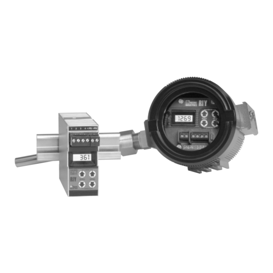
• Readouts in degrees Celsius or Fahrenheit, or ohms (only on units with LCD’s) Moore Industries’ Programmable Isolated RTD • Sensor type and number to be input to the RIY Transmitter (RIY) is a 2-wire, microprocessor-based • Upscale/downscale drive instrument that converts an RTD or ohms input into a •... - Page 4 If product information is ever required, make a note of the unit model number before contacting the The serial and model number for the HP-style RIY is factory. For fastest assistance, also note the unit located on the back panel of the unit. The serial and...
-
Page 5: Calibration
RIY. NOTE Consult the factory for availability of specific configuration options. EXAMPLE RIY / R0-0-100 C / 4-20MA / 12-42DC / -ND [HP] Unit Type Input Code Calibration Value Input Units of Measure Output... - Page 6 (units with LCD’s only); does not affect the output of the RIY CAUTION • increment zero or span values, respectively, The push buttons are not designed to be when pressed individually while in quick actuated with sharp, pointed objects.
- Page 7 This panel is bent over the top, right-side edge of the unit and is secured with a single screw on This switch determines the reaction of the RIY top. A Phillips-head screwdriver is required to output when an error is detected (during power-...
- Page 8 2. The lower table limit extends 5%, or more, of maximum span below the listed value. When this limit is exceeded, the RIY will clamp at the limit value and the display will read “–LO–”. For ohms ranges, 0Ω is the lower table limit.
- Page 9 Anytime a switch setting is changed while power is applied, one of the front panel push buttons must be When the RIY is in any display mode other than quick pressed to ensure that the RIY accepts and acknowl- ranging, such as the operate mode, standard ranging, edges the configuration change.
- Page 10 20 mA. But to effect any range changes, switch SW301-6 must be set to the ‘off’ position (keyboard enable). Reverse Output. The RIY can also be set up for reverse output , where the zero-percent output is 20 Figure 3. Units-of-Measure Labels for the LCD mA and the 100-percent output is 4 mA.
- Page 11 (voltage reading)/250 = mA. Ω position for units with this switch functional for keyboard enable. Table 3. RIY Calibration Equipment (Standard Ranging) Specifications Equipment Accuracy of ±0.01%, or better Decade Resistance Digital voltmeter, accuracy of ±0.005% or better; 250Ω precision Voltmeter and resistor, tolerance of ±0.01%...
- Page 12 Vdc (4 mA), repeat steps 6 and 7 until 5 Vdc 2. Connect RIY as shown in figure 4. Apply power. reading is obtained. 9. Set input device for full-scale input to RIY. 3. Press and hold either the Up or Down ZERO push button.
- Page 13 (with LCD) – –PS (SEE NOTES) The RIY must be equipped with an LCD to perform quick ranging. NOTES: 1. The input is ignored when the unit is configured for quick ranging. Figure 5. Quick Ranging Hookup Diagram The Interface Solution Experts...
- Page 14 RIY is configured for 10. Press and hold the Up or standard ranging. Check SW301-5. Down ZERO push button to If there is no change in the LCD, the RIY verify zero setting. is configured for keyboard lockout. ZERO Check SW301-6.
- Page 15 100- inputs , the following procedure allows you to verify percent differential input setting that produces a 100- the response of the RIY as you vary the inputs. percent (full-scale) output. To range an RIY for differential input operation, you...
- Page 16 –PS RESISTANCE BOX #1 – NOTES: 1. Notice that terminal 2 on the RIY is not used for this hookup. DC VOLTMETER 2. The specifications of both decade resistance boxes must meet or exceed those given in table 3. Figure 6. Differential Input Ranging Setup 5.
-
Page 17: Installation
Mounting the RIY electrical wires. The RIY is available in an HP- or DIN-style housing. On DIN-style units, the sensor input and loop-power Mounting considerations differ for each of these connections are made to removable terminal blocks. - Page 18 72.6 mm (2.86 in) ZERO SPAN 82.5 mm 61 mm (3.25 in) (2.40 in) CANCEL Figure 7. RIY, HP-style Outline Dimension (FL Housing shown) 35 mm 128.5 (1.38 in) (5.06 in) +PS –PS 80 mm (3.15 in) SAV E ZERO...
- Page 19 The shield of the wire set should be the connections necessary to operate the RIY. grounded to an earth ground potential as close to the RIY as possible. The HP-style unit has a grounding NOTE lug on its top that may be used for this purpose.
-
Page 20: Operation
LCD changes accordingly. tion as to the settings or operational status of the RIY. The LCD can also display the zero and span settings When a non-LCD unit is calibrated with standard... -
Page 21: Maintenance
LCD. (SW301-5 must be set to ‘on’ and SW301-6 set to 'off' The RIY is designed to operate reliably with a mini- to perform quick ranging.) The front panel push mum of field maintenance. - Page 22 RTD/Element #3 is open Ohms FLEX-SOR NOTE: For expanded switch setting information refer to the Calibration Section of the RIY User’s Manual. For expanded hookup information refer to the Installation Section. For expanded problem code information refer to the Operation Section.
-
Page 23: Intrinsic Safety
These diagrams must be used to augment the installa- Intrinsic Safety tion instructions earlier in this manual for units that are This page contains the installation diagram for the RIY to operate in areas requiring intrinsically safe instru- carrying the intrinsically safe option. It also includes mentation. - Page 24 22 The Interface Solution Experts...
- Page 25 The Interface Solution Experts...
- Page 26 4. Ship the equipment to the Moore Industries location nearest you. The returned equipment will be inspected and tested at the factory. A Moore Industries representative will contact the person designated on your documentation if more information is needed. The repaired equipment, or its replacement, will be returned to you in accordance with the shipping instructions furnished in your documentation.
Need help?
Do you have a question about the RIY and is the answer not in the manual?
Questions and answers