Table of Contents
Advertisement
Quick Links
Advertisement
Table of Contents

Related Manuals for Moore Industries TMZ


Summary of Contents for Moore Industries TMZ
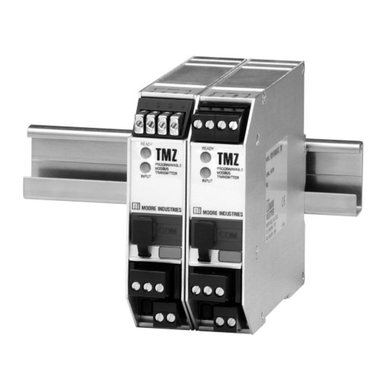
- Page 1 PC-Programmable MODBUS May 2016 Temperature Transmitter 225-720-02D TPRG Left: TMZ TPRG: PC-Programmable MODBUS Temperature Transmitter Right: TMZ HLPRG: PC-Programmable MODBUS Signal Converter All product names are registered trademarks of their respective companies.
-
Page 2: Table Of Contents
Specifications ....................5 Dimensions ........................7 Configuring the TMZ ..................8 Installing the Configuration Software ................9 Connecting the TMZ to the PC ..................9 PC Configuration Software Summary ............10 Status and Tool Bar Legend ................... 11 Configuration Screens ................. 12 Input .......................... - Page 3 Installation ..................... 16 Mounting the TMZ ......................16 Making the Electrical Connections ................. 16 Recommended Ground Wiring Practices ............... 16 CE Conformity ........................ 16 Operation ....................... 16 Maintenance ........................16 Customer Support ..................16 Appendix A: TMZ MODBUS Register Set........... 17...
-
Page 4: Introduction
32 units on a single maintain this instrument. drop of cable that consists of two pairs of wires. The TMZ has a READY LED to indicate the health of the About this Manual unit and an INPUT LED to indicate status. -
Page 5: Specifications
PC-Programmable MODBUS Temperature Transmitter Specifications Performance Input Accuracy: Performance Protection: ±5Vdc Ambient Operating & Storage (continued) Excitation Current (RTD Conditions Range: -40°C to +85°C See Table 4 Overall Accuracy: The and Ohm Inputs Only): (-40°F to +185°F) Effect of Ambient overall accuracy of the 250µA, ±10% Temperature on Cold... - Page 6 PC-Programmable MODBUS Temperature Transmitter Table 4. Accuracy with RTD, Thermocouple, Ohms, Potentiometer and Millivolt Inputs Maximum α Input Conformance Input Type Ohms Range Range Accuracy/Repeatability (2-, 3-, 4-Wire) -200 to 850°C -240 to 960°C 0.003850 (-328 to 1562°F) (-400 to 1760°F) 1000 Platinum ±0.1°C...
-
Page 7: Dimensions
PC-Programmable MODBUS Temperature Transmitter Figure 2. TMZ (TPRG) Dimensions WHEN INSTALLED 138mm (5.43 in) 133mm WHEN INSTALLED (5.24 in) 25mm 126mm (1.00 in) (4.97 in) READY 52mm PROGAMMABLE (2.05 in) MODBUS TRANSMITTER INPUT 100mm (3.94 in) 48mm (1.89 in) Table 5. Terminal Designations... -
Page 8: Configuring The Tmz
The software settings are downloaded to the transmitter in the form of a Configuration File and One of the benefits of the TMZ is that there are no stored in the instrument’s memory. You can save a internal or external controls to adjust or settings to backup copy of the file on your PC hard drive or disk. -
Page 9: Installing The Configuration Software
Double-click the installation program located in the folder. Follow the prompts to correctly The TMZ must be connected to the PC in order to: install the program. perform sensor trimming; assign a tag, descriptor or message;... -
Page 10: Pc Configuration Software Summary
PC-Programmable MODBUS Temperature Transmitter PC Configuration Software Summary Figure 5. TMZ (TPRG) PC Configuration Software Screen 4. Identification Parameters– Use this parameter to Once the default configuration has been saved to disk, it is safe to program other parameters. The PC place an identifying “Tag”... -
Page 11: Status And Tool Bar Legend
Controls whether Tool and Status MODBUS parameters. Refer to the MODBUS section Bars are viewed on the screen for a complete description. Displays the version of the TMZ Configuration Program Default/Factory Configurations The following are the default factory settings for your unit. -
Page 12: Configuration Screens
PC-Programmable MODBUS Temperature Transmitter Configuration Screens Running Average Filter– This function is for filtering the input signal. The TMZ provides this filter with a user-selected range between 1 and 16. Factory Input default is 4. Note: Figure 6. Input Tab... -
Page 13: Trimming
PC-Programmable MODBUS Temperature Transmitter Trimming Note: Once you have configured all parameters, download Figure 7. Trimming Tab to the unit by selecting “Download” in the Transfer dropdown menu located in the Status Bar. You may also download by clicking the button in the Tool Bar. - Page 14 4. After all of your data has been entered, you must use the Custom Curve dropdown menu to save your newly created custom (“Save Custom Curve”) and to download it to your TMZ (“Download Custom Curve”). Note: Once you have configured all parameters, download to the unit by selecting “Download”...
-
Page 15: Modbus
Tool Bar. Communications– Used to set MODBUS Address, Baud Rate and Parity parameters. Address- The number that the TMZ uses to identify itself on the MODBUS network. It is configurable from 1 to 247. By default, the assigned MODBUS address is 01. -
Page 16: Installation
Recommended Ground Wiring Practices section in order to meet the EN 61326 requirements set forth in Mounting the TMZ the applicable EMC directive. The TMZ can be mounted on standard DIN mounting Operation rails. Once programmed, calibrated, installed, and supplied... -
Page 17: Appendix A: Tmz Modbus Register Set
PC-Programmable MODBUS Temperature Transmitter Appendix A: TMZ MODBUS Register Set Table A-1 contains all of the MODBUS integer registers supported by the TMZ. These registers constitute both the 30000 and 40000 register set. Table A-1. MODBUS Register Table Register Variable... - Page 18 4. Ship the equipment to the Moore Industries location nearest you. The returned equipment will be inspected and tested at the factory. A Moore Industries rep- resentative will contact the person designated on your documentation if more information is needed.
- Page 19 TMZ (TPRG) User’s Manual, 225- 720-02. This document addresses the TMZ (2TPRG) dual input model of the TMZ. The TMZ (2TPRG) has two individually configurable sensor inputs and a single isolated MODBUS output. The inputs are not isolated from each other.
- Page 20 Power Consumption: properly 1w max. Input Impedance: T/C and mV inputs, 40Mohms, nominal Specifications and information subject to change without notice. *For detailed sensor accuracy specifications, please refer to Tables 1-4 in the TMZ TPRG User Manual. Demand Moore Reliability...
- Page 21 User’s Manual Supplement TMZ (2TPRG) Dual Input Model Figure S-2. Dimensions of the TMZ (2TPRG) 45mm (1.77 in) 133mm (5.25 in) PROGAMMABLE MODBUS TRANSMITTER DUAL INPUT READY INPUT 1 100mm INPUT 2 102mm (3.94 in) (4.03 in) -2528A-LB2 Table S1. Terminal Designations...
- Page 22 User’s Manual Supplement TMZ (2TPRG) Dual Input Model Figure S-3. Hooking-Up the TMZ (2TPRG) MILLIVOLT MILLIVOLT SOURCE SOURCE OR T/C OR T/C SIMULATOR SIMULATOR MODBUS Host OHMS OR OHMS OR 2-WIRE 2-WIRE SIMULATOR SIMULATOR PROGAMMABLE MODBUS TRANSMITTER DUAL INPUT READY...
- Page 23 TMZ (2TPRG) Dual Input Model PC Configuration Software Summary of TMZ (2TPRG) Dual Input Figure S-4. Main Screen of the TMZ (2TPRG) PC Configuration Software Program for Dual Input Units 6. TMZ Device Info– Displays your unit configuration, Once the default configuration has been saved to disk, ID, hardware revision and Software revision.
- Page 24 Configuration of the Input windows follows address: 1 the general parameters, with slight variation, as Baud Rate: 9600 described in the TMZ (TPRG) User’s Manual (Page 12). Parity: None lSw Input Type– Select your input type (RTD 2-wire, RTD 3-wire or RTD 4-wire).
- Page 25 TMZ (2TPRG) Dual Input Model MODBUS Scaling MODBUS configuration remains unchanged as Note: described in the TMZ (TPRG) User’s Manual (Page15). The Custom Curve feature is not available with the TMZ (2TPRG). Figure S-6. Scaling Tab The following instructions apply to Channel 1 and Channel 2 Scaling configuration.
- Page 26 TMZ (2TPRG) Dual Input Model TMZ MODBUS Register Set Table S-2 contains all of the MODBUS integer registers supported by the TMZ (2TPRG) dual input model. These registers constitute both the 30000 and 40000 register set. Table S-2. MODBUS Register Table...
Need help?
Do you have a question about the TMZ and is the answer not in the manual?
Questions and answers