
Related Manuals for Moore Industries STZ


Summary of Contents for Moore Industries STZ
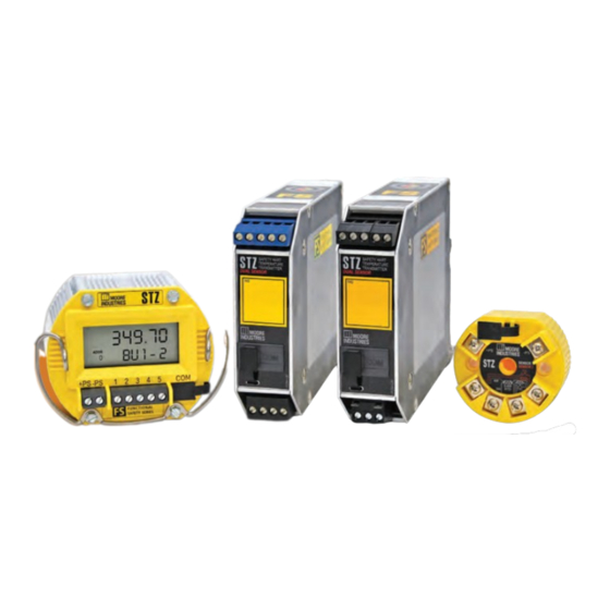
- Page 1 No. 238-760-00K May 2019 Functional Safety Dual Input Smart HART ® Temperature Transmitter...
- Page 2 We perform a sequence of stringent quality assurance checks on every unit we ship. If any Moore Industries product fails to perform up to rated specifications, call us for help. Our highly skilled staff of trained technicians and engineers pride themselves on their ability to provide timely, accurate, and practical answers to your process instrumentation questions.
- Page 3 All Moore Industries instrumentation should only be used for the purpose and in the manner described in this manual. If you use this product in a manner other than that for which it was intended, unpredictable behavior could ensue with possible hazardous consequences.
-
Page 4: Table Of Contents
Installation in Hazardous Locations ..............34 Specific Conditions of Use ..................34 Section 4 - Configuration Programming Device Description Menu on STZ with HART Communicator hand- held devices ......................47 DD Device Setup Reference Guide ...............49 Section 5 - Configuration using FDT/DTM Software STZ DTM Parameter in Basic Setup Configuration .......... - Page 5 Point-to-Point Loops with Remote Programmability ........124 Using HART monitoring for Additional Diagnostic Data ........126 SIL 3 Application Example ...................127 Section 9 - Specifications Section 10- Ordering Information Section 11 - Certification Information Warranty Disclaimer Moore Industries-International, Inc. www.miinet.com - 5 -...
-
Page 6: Stz Quick Start Guide
May 2019 STZ Quick Start Guide The STZ is ready to install and is either set up with your specified configuration or the default configuration below. If you need to change any parameters this can be done using a HART handheld configurator or FDT/DTM application (see Sections 4 &... -
Page 7: Section 1 - Introduction
Overview The STZ has the ability to accept one or two sensor inputs. The output of the STZ can be configured to reflect either sensor 1, sensor 2, average, differential, backup, low or high select. In backup, the STZ automatically switches to the secondary sensor input if the primary sensor fails;... -
Page 8: Model Numbers And Options
STZ [DIN] – (see figure 3.2) 2-wire and/or 3-wire sensors. 4-wire sensors (RTDs) cannot be used. STZ [HPP] – (see figure 3.4) Sensor 1 can be configured as 2-wire or 3-wire sensor. Sensor 2 is then restricted to a 2-wire sensor. - Page 9 Units with this option have blue input terminals. HOUSING [HP] STZ with display is available in an HP housing. The HP unit can also be ordered in an explosion proof or protective enclosure e.g., BH, SB etc. or with a clip for DIN-rail or track mounting.
-
Page 10: Measurement Modes And Device Variables
May 2019 Measurement Modes and Device Variables The STZ can support one or two sensor inputs. With one input it provides an output which is proportional to the input with options for trimming, custom linearization and scaling. With two sensor inputs there are many other measurement modes: Single Measurement - Sensor 1 or Sensor 2 can be selected Backup Measurement - Sensor 1 fail to Sensor 2 or Sensor 2 fail to Sensor 1. - Page 11 The STZ supports enhanced broadcast messaging more commonly referred to as burst mode. When set to burst mode, the STZ will proactively send out messages instead of waiting for the host to request them. This enables event driven communication (high, low, deviation of signal or change in status) and/or timed communication (every 20 seconds) to the host.
-
Page 12: Sensor Diagnostics
May 2019 Sensor Diagnostics As part of the enhanced device intelligence, the STZ performs Total Sensor Diagnostics. This can save you downtime by letting you know when a problem occurs, what type and it’s location. Some of these diagnostics such as drift alert and corrosion detection can also be used for predictive diagnostics to warn of future problems. - Page 13 This can lead to false sensor readings. The STZ can be configured to detect these false readings by using a Range Alarm to monitor the absolute differential between two sensors (e.g., RTD & T/C or two RTDs or T/Cs) at the same point.
- Page 14 See chart below for clarification. Selecting Warning will set a fault message on the STZ display and send a HART message to any HART Handheld or HART monitoring HOST. In addition an alert will be sent to any FDT host that is communicating with the transmitter.
-
Page 15: Section 2 - Calibration And Bench Check
STZ HPP (4 Terminals) Input Connections STZ HPP Note: STZ [HPP] (see gure 3.4) – When using two input sensors, Sensor 1 can be con gured as 2-wire or 3-wire sensor. Sensor 2 is then restricted to a 2-wire sensor. - Page 16 Sensor trimming increases the measurement accuracy of your instrument by matching the reading of its actual input to its scaling. The STZ offers the use of a trimming feature that can be accessed using a HART Communicator, a HART Host, or an FDT Host (such as PACTware).
- Page 17 Se ngs This will help you to be sure to apply the correct input with which to trim your STZ. By example: If the Sensor 1 Measure Mode is “RTD 4 wire” and the Sensor 1 Input Type is “Pt 3850 1000 ohm”...
- Page 18 Trimming for a thermocouple input will be similar, except you will be providing an accurate millivolt signal to simulate temperature. To perform the Output Trimming of the STZ set up the equipment specified in Table 2.1. then use your HART Communicator, follow steps below and refer to Figure 2.5 for clarity.
- Page 19 Follow the instructions on the screen of your HART Communicator and then proceed to “Trim Full”. Use your voltmeter to measure the voltage drop across the 250Ω resistor. A 20mA output will read as 5V across the resistor. Moore Industries-International, Inc. www.miinet.com - 19 -...
- Page 20 For users who already have an FDT Frame Application, all the following information is still relevant. For more information on FDT/DTM please refer to www.fdtgroup.org. To perform the Input Trimming of the STZ set up equipment in Table 2.2 as shown in Figure 2.7. Table 2.2. Necessary Equipment...
- Page 21 Check the Configure Sensors settings in PACTware. This will help you to be sure to apply the correct input with which to trim your STZ. By example: If the Sensor 1 Input is “3W RTD” and the Type is “Pt3850-1000” and Engineering Units is “degrees Celsius” then you should be using an accurate resistance source (such as a decade box) to emulate the 3-wire, Pt 3850, 1000Ω...
- Page 22 Primary Variable and the range is defined as 0-100 Degrees C. Now you are ready to do the actual input trimming of your STZ. Proceed to Sensor 1 Trim in PACTware as seen in Figure 2.10.
- Page 23 Full point is 100° C the input you apply to the instrument will be 1385.00Ω. 7. When your reading stabilizes press the Trim Upper Point button and your Sensor 1 Reading should now read the correct Trim Point Value (100 in this example). Moore Industries-International, Inc. www.miinet.com - 23 -...
- Page 24 By example: if the STZ is putting out 12.0mA and your DCS is reading 11.85mA you can trim the output of the STZ so that the two readings will match. Note: trimming of the analog output will not affect the HART digital data.
- Page 25 There is no need to press the “Apply” button as all trim changes take immediate effect. Note: When complete BE SURE to press the “Clear” button to return control of the output back to your STZ. Moore Industries-International, Inc. www.miinet.com...
-
Page 26: Bench Check
Doing this will ensure it is operating within your expectations or requirements. Bench Check using a HART Handheld Communicator To perform the bench check of your STZ set up the equipment in Table 2.3 as shown in Figures 2.13. - Page 27 If possible, use the exact temperature sensor (RTD or thermocouple) that you will be using in your final application. Apply power to the STZ and see that it is reading the correct ambient temperature and providing the correct output for the given input.
-
Page 28: Section 3 - Installation And Wiring
STZ HPP (4 Terminals) Input Connections STZ HPP Note: STZ [HPP] (see gure 3.4) – When using two input sensors, Sensor 1 can be con gured as 2-wire or 3-wire sensor. Sensor 2 is then restricted to a 2-wire sensor. -
Page 29: Dimensions
May 2019 Dimensions Figure 3.2. Dimensions of STZ DIN Housing 4.04 in [102.6mm] 1.11 in 5.31 in [28mm] [135mm] Figure 3.3. Dimensions of STZ HP Display Housing 75mm 63.5mm (2.97 in) (2.50 in) 62mm ADDR ADDR (2.45 in) Figure 3.4. Dimensions of STZ HPP Housing... - Page 30 22mm (0.87 in) TOP VIEW 64mm (2.52 in) 10mm (0.38 in) 102mm (4.02 in) 68mm 124mm 68mm (2.68 in) ADDR ADDR ADDR ADDR (4.88 in) (2.68 in) 84mm (3.31 in) 25mm (1.00 in) - 30 - www.miinet.com Moore Industries-International, Inc.
- Page 31 57mm (3.50 in) 76mm (2.25 in) (2.99 in) 70mm 25.4mm (2.75 in) (1.0 in) 31mm (1.25 in) 57mm 6.6mm (2.25 in) (.26 in) SIDE VIEW 70mm (2.75 in) 89mm (3.50 in) BACK VIEW Moore Industries-International, Inc. www.miinet.com - 31 -...
- Page 32 All terminals are rated CAT I. Equipment Ratings The STZ does not generate hazardous voltages, they provide a low voltage (0-1V) input and a 4-20mA output. Products connected to the STZ should be designed to receive this type of input.
- Page 33 Note: Some of Moore Industries’ instruments can be classified as receivers (IPT2, IPX2, etc.) and some can be classified as transmitters (TRX, STZ etc.) while some are both a receiver and a transmitter (SPA2, HIM, etc). Hence, your shield ground connections should be appropriate for the type of signal line being shielded.
-
Page 34: Installation In Hazardous Locations
This section contains important information regarding installation of STZ in Hazardous Area Locations. Note: The STZ DIN is suitable for Class I, Division 2, Groups A-D or Non-Hazardous locations only. Note: The STZ DIN with the -AIS Option is an associated apparatus which is suitable for Non-Hazardous or Class I, Division 2/Zone 2 locations with sensor terminals connected to equipment in Class I, II, III, Division 1/Zone 0 locations. - Page 35 The following instructions must be adhered to when the STZ is used in hazardous locations and potentially explosive atmospheres. Note: The STZ-DIN with the -AIS Option has its’ own Specific Conditions of Use. See page 38 for instructions. cFMus Installations...
- Page 36 IP54. On installation of Zone 2 equipment, the STZ shall be provided with supply transient protection external to the apparatus such that the voltage at the supply terminals of the STZ does not exceed 58.8V peak or 58.8Vdc.
- Page 37 IP54. On installation, the STZ shall be provided with supply transient protection external to the apparatus such that the voltage at the supply terminals of the STZ does not exceed 119V peak or 119Vdc. The COM port shall not be used in Hazardous areas.
- Page 38 Functional Safety Dual Input Smart HART® Temperature Transmitter May 2019 Specific Conditions of Use The following instructions must be adhered to when the STZ with –AIS Option is used in unclassified/non-hazardous locations or hazardous locations/potentially explosive atmospheres. Note: Programming of the STZ through the communication port shall only be done in an unclassified location using the Moore Industries USB cable, Part Number 804-030-26.
- Page 39 The non-metallic parts incorporated in the STZ DIN mount housing may generate an ignition-capable level of electrostatic charge. The STZ shall not be installed in a location where the external conditions are conducive to the build-up of electrostatic charge on such surfaces. Additionally, the equipment shall only be cleaned with a damp cloth.
-
Page 40: Section 4 - Configuration
May 2019 Section 4 - Configuration The STZ can be configured using a HART communicator, HART host or a PC running an FDT/ DTM program. All functions can be configured using either method with the exception of custom curves which cannot be generated or imported using the HART communicator. However, once custom curves have been saved in the unit they can be selected using the HART Communicator. - Page 41 Configure the PV Range (PV URV and LRV). Configure the AO’s Range, limits, and fail response. Dual with Mixed Sensors The STZ can be configured for use with two different sensors (for example, T/C and a RTD). Follow these steps: Configure the sensor Use the “Configure Input Types”...
- Page 42 PV Damping: PV Damping allows you to introduce a delay into the response of your unit in order to stop short-lived spikes from initiating faults and generating fault messages. The damping time setting is the time PV takes to make a 63% change in response to a step change. - 42 - www.miinet.com Moore Industries-International, Inc.
- Page 43 AO Trimming increases the accuracy of your instrument by calibrating its analog output to the device that is receiving the output. This ensures that the instruments are matched to each other. Display (STZ [HP] only) All dynamic and additional device variables in the transmitter can be selected for display. If none are selected, then the unit will behave as though the PV is marked for display.
- Page 44 May 2019 HART Broadcast Messaging (Burst Mode) When set to burst mode, the STZ will proactively send out messages instead of waiting for the host to request them. This enables event driven communication (high, low, deviation of signal or change in status) and/or timed communication (every x seconds) to the host.
- Page 45 5 minutes (when PV does not exceed 50degC) HART command 3: Read Dynamic Variables and Loop Current Update period: 1 second; Maximum update period: 300 seconds Trigger Mode: Rising Trigger Level: 50.00 Trigger Units: degrees Celsius Moore Industries-International, Inc. www.miinet.com - 45 -...
- Page 46 Please refer to Section 1 for more detailed information on Sensor Diagnostics. Input Quality Alarms The STZ also allows the user to determine how certain types of input quality issues are handled and how they can affect the Device Variables, Dynamic Variables and AO. There are 3 different quality alarms: Measurement out of Conformance Range, Allow Limited and Allow Dropping.
-
Page 47: Programming Device Description Menu On Stz With Hart Communicator Handheld Devices
Online Menu The Online menu displays the current process value of your application, the lower and upper range values and the actual output current. Use the Device Setup menu to configure the STZ as detailed in the rest of this section. - Page 48 User’s Manual 238-760-00K Functional Safety Dual Input Smart HART® Temperature Transmitter May 2019 Figure 4.1. STZ Configuration Online menu overview 4000 ohms Process Configure Online Menu Refresh Device Var Sensor 1 PV Q uality Variables Input Types PV Quality RJC Temp...
-
Page 49: Dd Device Setup Reference Guide
Ranging & Mapping Variable Mapping- assigns the Device Variables (eg. SEN1, BU1-2) to the HART Variables (PV, SV etc.) Smart Range –sets the PV lower range and upper range values to AO 0-100% Moore Industries-International, Inc. www.miinet.com - 49 -... - Page 50 Device id, Hardware revision (read only) *Burst Configuration - can be configured to send out up to 3 burst messages Display (STZ HP only) Select Dynamic & Device Variables to be displayed Number of Decimal Places *Configure Custom EGU & Custom Name...
- Page 51 Set up corrosion detection on Sensor 1 and/or 2 *Unlatch Range Alarm Unlatch any of the 4 Range Alarms. Review This menu is for information only. It provides configuration information for: Device Parameters Device Information Moore Industries-International, Inc. www.miinet.com - 51 -...
- Page 52 May 2019 Device Setup Menu The Device Setup menu allows you to access the following menus: Process Variable, Setup, Custom Calibration and Review refer to Figure 4.2. Figure 4.2. STZ Device Setup menu Online Menu Process See Figure 4.3 Variables...
- Page 53 After selecting a specific Range Alarm (1 to 4) to configure, you can select “Warning” or “Alarm (AO Fail)”. Selecting Warning sends a message to the HART Handheld/FDT host, STZ display and sets a HART status bit. Selecting Alarm will also drive the Analog output to Fail Mode. The absolute differential Device Variable used for the Drift Alert can also be assigned/mapped to any of the HART Dynamic Variables PV, SV, TV or QV.
- Page 54 Configure Sensor– The Configure Sensor menu allows you to access to the following list for configuration: Configure Input Types, RJC Temp, Sensor 1, and Sensor 2 refer to Figure 4.5. Note: After making all desired changes enter SEND to update the unit. Figure 4.5. STZ Input menu 50 Hz 60 Hz...
- Page 55 Configure Input Types: Selecting this will enable to configure Sensor 1 and Sensor 2 as follows: Note: While the STZ will accept a dual input sensor configuration the following limitations apply only when using two input sensors: STZ [HP] 2-wire and/or 3-wire sensors. 4-wire sensors (RTDs) cannot be used.
- Page 56 Location, Name, and Config Type. Refer to Figure 4.5 for clarification. Note: You must hit the SEND button to refresh and update the STZ unit, otherwise hitting HOME or BACK arrow will not make or update the desired RJC Temp EGU change/update.
- Page 57 “Internal Flash” stores file directly into the HART handheld communicator internal flash. While selecting “System Card” allows you to save to the installed system card (SD memory card). Note: After making all desired changes enter SEND to update the unit. Moore Industries-International, Inc. www.miinet.com - 57 -...
- Page 58 Sensor X Scal e Min. Enter Sensor X Scale M in. Sensor X Scal e Max. Enter Sensor X Scale M ax. Figure 4.7. STZ Custom Curve for Sensor 1 and Sensor 2 in Input menu SX Measure Mode Configure S1 Input Type...
- Page 59 Any value which falls within the range of the mapped device variable LSL and USL may be used for PV LRV and PV URV. Note: After making all desired changes enter SEND to update the unit. Figure 4.8. STZ Ranging and Mapping within Input menu Filter Change Variable Mapping...
- Page 60 Backup 1-2 but is the same for any of the given Device variables. Note: The Dual Input menu is only visible if Advance Settings is Enabled. Note: After making all desired changes enter SEND to update the unit. Figure 4.9. STZ Dual input Default Config Disabled Backup 1-2...
- Page 61 AO Full, AO URV (Under range value), AO ORV (Over range value), Fail Mode, and AO Fail to Value. See Figure 4.10 below for further clarification. Note: After making all desired changes enter SEND to update the unit. Figure 4.10. STZ Analog Output Default Config Config Wizards...
- Page 62 See HART Burst Message description in the Feature Overiew at the begiinning of Section 4 for more information. Note: The Burst Configuration menu is only visible if Advance Settings is Enabled. Note: After making all desired changes enter SEND to update the unit. - 62 - www.miinet.com Moore Industries-International, Inc.
- Page 63 User’s Manual 238-760-00K Functional Safety Dual Input Smart HART® Temperature Transmitter May 2019 Figure 4.11. STZ HART Settings menu Default Config Config Wizards Poll Addr Enter Poll Addr Input Num req preams Displays Num req preams Cmd 1: PV Dual Input*...
- Page 64 Functional Safety Dual Input Smart HART® Temperature Transmitter May 2019 Display Menu (STZ HP only) The Display menu allows you to select which variables are shown and also allows for custom names and engineering units (EGU). Refer to Figure 4.12 for further clarification.
- Page 65 If 3 Decimal places are selected, 1.234 will be shown. However the DP will be moved to allow 123.45 to be shown. Moore Industries-International, Inc. www.miinet.com - 65 -...
- Page 66 For displayed Device Variables, the custom name will replace the default name. Dynamic Variables cannot have a custom name. However when the underlying Device Variable’s name is shown, the custom name is shown instead. - 66 - www.miinet.com Moore Industries-International, Inc.
- Page 67 Source: [Primary Variable] The Variable to be used as a source for the Range Alarm Response: [Warning] How to react if the specified condition occurs: Warning - Sends a warning message to the HART Handheld/FDT host, STZ HP display and sets a HART status bit.
- Page 68 User’s Manual 238-760-00K Functional Safety Dual Input Smart HART® Temperature Transmitter May 2019 Figure 4.13. STZ System Configuration and Advance Settings Menus Default Config RJC Temp Sensor 1 Config Wizards Allow Meas out of Con Sensor 2 On/OFF Backup 1-2...
- Page 69 Status – Directs you to a sub-menu. When accessed, you will come to the following menu options, System Status, Addl Status Bytes, Subsystem Status, Input Status, User Cfg Status, and Dev Variable Status. Refer to Figure 4.14. Figure 4.14. STZ Status menu within the Custom Calibration Menu Sys Stat Summary Broken RJC...
- Page 70 Input Capture– Input Capture is used to match the device input and output zero and full scale to a known value. Adjust input sensor to 0% value to STZ and follow the screen instructions. This will set the device’s output to known 4mA value. Adjust input sensor to 100% value to STZ and follow the screen instructions.
- Page 71 User’s Manual 238-760-00K Functional Safety Dual Input Smart HART® Temperature Transmitter May 2019 Figure 4.15. STZ Input (PV), Variable Trim, AO Trim, AO Trim Reset, and Loop Test within the Custom Calibration Menu Process Variables Status Setup Sensor1 Sensor2 Custom...
-
Page 72: Section 5 - Configuration Using Fdt/Dtm Software
Moore Industries has always provided manufacturer-specific programs to operate our field instruments to the full extent. STZ will require the use of an FDT frame application, which allows configuration and adjustment of any and all field instruments ,which have a DTM. For users who do not already have an FDT frame application, Moore Industries provides PACTware. - Page 73 HART Communication FDT DTM - This is for using a HART modem to connect to MII MISP Communications DTM - This is for using a Moore Industries serial or USB cable MII STZ DTM - This is the Device DTM for the STZ You will also find individual DTM installers on the website and Moore Tools CD in Comms and Device folders.
- Page 74 Industries.exe Moore Industries MISP DTM Installation If you want to communicate with the STZ using the USB communications cable, you will need to install the MISP DTM. The MISP DTM can be found on the Moore Industries Configuration Tools CD, or from our website www.miinet.com.
- Page 75 HART Communications DTM: is a Communication DTM for use of HART devices via HART modem. MISP Communications DTM: is a Moore Industries Serial Protocol which allows communication via Fuse-Protected USB Communications cable (P/N: 804-030-26). Figure 5.1. STZ HPP hook-up diagram for HART or MISP DTM configurations. Current Meter – Load=250 ohms...
- Page 76 User’s Manual 238-760-00K Functional Safety Dual Input Smart HART® Temperature Transmitter May 2019 Figure 5.3. STZ DIN hook-up diagram for HART or MISP DTM configurations. Current Meter – Load= 250 ohms 12-24Vdc Power Supply HART Modem To COM Port HART Held...
- Page 77 To configure the MISP Communications DTM you will need to add necessary DTMs within the PACTware software to start your configuration. You will also need to have a Moore Industries Fuse Protected USB Communications Cable (sold separately P/N:804-030-26). Refer to Fuse Protected USB Communications Cable documentation for installation of USB Communications Utility and configuration.
- Page 78 Port is selected and you have applied it to parameters the small Pencil icon will disappear. If Pencil icon is still visible, it indicates that the change has not been applied to device. Figure 5.7. Selecting correct COM port for the MII MISP Communication DTM. - 78 - www.miinet.com Moore Industries-International, Inc.
- Page 79 Figure 5.8. COM Port Confirmation 8. Next you will right click on “MISP:COM 12” and select “Add device”. Select desired STZ DTM from list and click “Ok”. See Figures 5.9 and 5.10. Figure 5.9. Adding Device to MISP:COM Port Figure 5.10. Selecting desired STZ DTM Moore Industries-International, Inc.
- Page 80 Functional Safety Dual Input Smart HART® Temperature Transmitter May 2019 9. Now right click on selected DTM (i.e. STZ [HP]) in the Device Tag menu and select “Connect”. You will now see the “online state” turn green to indicate you have a connection.
- Page 81 To configure the HART Communications DTM you will need to add necessary DTMs within the FDT frame application (PACTware) software to start your configuration. Follow steps below to achieve this. 1. Connect STZ unit per Figures 5.1- 5.3. 2. Launch FDT frame application (PACTware) software. Figure 5.14. HART configuration adding a device.
- Page 82 Functional Safety Dual Input Smart HART® Temperature Transmitter May 2019 4. Select the HART Communications DTM and enter OK Figure 5.16. COM Port Parameters 5. Right Click on COM1 and select “Parameter”. Figure 5.17. Selecting COM Port Parameters - 82 - www.miinet.com Moore Industries-International, Inc.
- Page 83 “Connect”. You will now see the “online state” turn green to indicate you have a connection. Figure 5.19. Adding Device to COM Port 8. Next you will right click on “COM11” and select “Add device”. Select desired “STZ” DTM and click “Ok”. Figure 5.20. Selecting desired Device DTM for STZ Moore Industries-International, Inc.
- Page 84 Figure 5.21. Connecting Device DTM for STZ 10. Right click on “right click on selected DTM (i.e. STZ [HP]) in the Device Tag menu and select “Parameters”. This will bring up screen for the DTM parameters. You are now ready to start your configuration of the device.
- Page 85 The following menu options and terminology are specific to PACTware but other FDT frame applications have similar menus. This PACTware menu is common for all device DTMs and only the ‘Additional Functions’ submenu has STZ specifics. Where the menu is grayed out this feature is not available for the STZ.
- Page 86 The Set HART Access Mode allows user to select from Full Access, Read Only, or Disable. In order for this feature to work you must be connected using the MISP Communications DTM in conjunction with the STZ DTM. Full Access: Selecting this will allow full HART communications with the device (read and write).
- Page 87 AO Zero & Full Values AO Under Range & Over Range Values AO Fail Mode (High, Low, Hold Last, Fail to Value) Display (STZ HP only) Select Dynamic & Device Variables to be displayed Number of Decimal Places *Configure Custom EGU & Custom Name...
-
Page 88: Stz Dtm Parameter In Basic Setup Configuration
The Parameter Menu page consists of five main Menu options Input, Analog Output, Display, HART Settings, and Custom Calibration. Note: The Display option will only be active for the STZ HP. It will be grayed out for the STZ HPP and STZ DIN. - Page 89 STZ [DIN] (see figure 3.2) - 2-wire and/or 3-wire sensors. 4-wire sensors (RTDs) cannot be used. STZ [HPP] (see figure 3.4) – Sensor 1 can be configured as 2-wire or 3-wire sensor. Sensor 2 is then restricted to a 2-wire sensor.
- Page 90 Sensor 1 and 2 Running Average Filter Setting (1-16) : This function is for filtering the input signal. The STZ has a running average filter with a user-selected range between 1 and 16. 1. Enter the Running Average Filter Setting value you desire.
- Page 91 The damping time setting is the time PV takes to make a 63% change in response to a step change. Figure 5.27. STZ Parameters Input Ranging and Mapping Moore Industries-International, Inc. www.miinet.com...
- Page 92 Use this portion of the menu to set the AO Zero, AO Full, AO URV (under range value), AO ORV (over range value), AO Fail MODE and AO Fail Mode values, to trim the output and to reset the trimmed output. Figure 5.28. STZ Parameters Analog Output - 92 - www.miinet.com...
- Page 93 The Display menu allows you to select which variables are shown and also allows for custom names and engineering units (EGU). Refer to Figure 5.29 for further clarification. Figure 5.29. STZ HP Display Menu Parameters Analog Output When PV, SV, TV, or QV are selected for display, each will result in three screens.
- Page 94 HART Revision– This is a read-only corresponds to the HART revision installed on field device. Revision– This is a read-only value corresponds to the revision of the Firmware of Firmware the field device. - 94 - www.miinet.com Moore Industries-International, Inc.
- Page 95 User’s Manual 238-760-00K Functional Safety Dual Input Smart HART® Temperature Transmitter May 2019 Figure 5.30. STZ HART Settings Moore Industries-International, Inc. www.miinet.com - 95 -...
- Page 96 Lower” or “PV Capture Upper” button to achieve this. Menu displays values for the following PV Device Variable, PV Lower Limit, PV Upper Limit, PV Lower Range Value, PV Upper Range Value, PV, and PV Status. See Figure 5.32 Figure 5.32. STZ Custom Calibration Menu - Input (PV) Capture - 96 - www.miinet.com...
- Page 97 Trim Result value. Refer to Figure 5.33. Sensor 2 Trim Is identical to the Sensor 1 Trim menu when Sensor 2 is enabled. Figure 5.33. STZ Custom Calibration Menu - Sensor 1 and Sensor 2 Trim Moore Industries-International, Inc. www.miinet.com...
- Page 98 Once the desired value is obtained, click on the “Clear” button. Note: If you do not click the Clear button, the Analog Output will remain in manual mode and will NOT follow the input signal. 10. You are done with one point trimming. - 98 - www.miinet.com Moore Industries-International, Inc.
- Page 99 Note: If you do not click the Clear button, the Analog Output will remain in manual mode and will NOT follow the input signal. 11. You are done with two point trimming. Figure 5.34. STZ Custom Calibration Menu - AO Loop Current Test/Trim Moore Industries-International, Inc. www.miinet.com...
- Page 100 (active). Select desired Device Variable enter a value within the allowed range and click Set button. Use the Clear button to clear all set simulations. See figure 5.35. Figure 5.35. STZ Custom Calibration Menu - Input Simulation Note: Before exiting this screen, remember to hit the Clear button or the Device Variables will remain set to their simulated values.
-
Page 101: Stz Dtm Parameter Advanced Setup Configuration
STZ DTM Parameter Advanced Setup Configuration The Advanced Setup menu contains all the Basic Setup plus the advanced features please refer to the Basic Setup description in addition to this section. Figure 5.36. STZ Parameters Page Menu for Advanced Setup Moore Industries-International, Inc. www.miinet.com... - Page 102 Note: This is the only location in where you are able to enable the Sensor Corrosion feature, furthermore this feature and its settings are only available when Input type is T/C, 3-Wire RTD, or 4-Wire RTD. Figure 5.38. STZ Sensor 1/2 Menu for Advanced Setup - 102 - www.miinet.com...
- Page 103 Scaling – This allows you to customize your display for your application. By example, if your process is sending a -200°C to 850°C signal to the STZ and you wish to view the input as 0-100% then this can be accomplished with the Scaling feature.
- Page 104 Configuration Software. This makes it simple to save the custom table for downloading to multiple units or for backup purposes. See Figure 5.41. Figure 5.41. STZ Custom Curves 1-4 in the System Configuration Menu for Advanced Setup - 104 - www.miinet.com...
- Page 105 Custom Curve section, values for your custom table can be entered here. See Figure 5.42 Figure 5.42. STZ Custom Curves Data 1-4 in the System Configuration Menu for Advanced Setup Note: Importing and exporting of .csv files for Custom Curves is done via the Additional Functions Menu in STZ DTM.
- Page 106 Response: [Warning] How to react if the specified condition occurs: Warning - Sends a warning message to the HART Handheld/DTM, STZ HP display and sets a HART status bit. Alarm - Sends the AO into fail mode and sends an alarm message to the HART Handheld/DTM, STZ HP display.
- Page 107 Configure Custom EGU– The Configure Custom (EGU) allows you to enable and assign a custom EGU of your choice. See Figure 5.45 for clarification. Figure 5.45. STZ Configure Custom EGU in Display Menu for Advanced Setup Moore Industries-International, Inc. www.miinet.com...
- Page 108 HART Burst Message 1-3– Here you can enable or disable and configure HART Burst messages 1-3. See Figure 5.47 for clarification. Figure 5.47. STZ HART Burst Messages 1-3 in HART Settings Menu for Advanced Setup - 108 - www.miinet.com...
- Page 109 This menu allows you to capture the nominal sensor resistance value, you can also check the current resistance value and corrosion the status. For a more detailed explanation refer to Corrosion Detection in Section 1. Figure 5.48. STZ Custom Calibration Menu - Sensor 1 Corrosion and Sensor 2 Corrosion Moore Industries-International, Inc. www.miinet.com...
-
Page 110: Section 6 - Operation And Maintenance
Note: If you are not getting HART data from the STZ, its HART mode may be set to Off. You will need to check the HART mode using the FDT/DTM and USB cable (see Section 5 for details). - Page 111 Device Variables and/or the AO response. Input Quality Alarms The STZ also allows the user to determine how certain types of input quality issues are handled and how they can affect the Device Variables and their mapped Dynamic Variables/AO. There are 3 different quality alarms: Measurement out of Conformance Range, Allow Limited and Allow Dropping.
- Page 112 When one or more failure condition is detected all error messages will be displayed on the STZ HP in a cyclic manner for a period of 2 seconds per message.
- Page 113 User’s Manual 238-760-00K Functional Safety Dual Input Smart HART® Temperature Transmitter May 2019 Table 6.2. STZ Display Errors - System STZ HP Display Condition ERROR NVMEM Failure to restore configuration from non-volatile storage ITRNL INVLD Stored Factory information is invalid...
- Page 114 Functional Safety Dual Input Smart HART® Temperature Transmitter May 2019 HART Status Registers The STZ provides the following status registers per the HART standards. Field Device Status A byte indicating the “current operating status of the field device”. Among the bits are “Device Malfunction” and “More Status Available”...
- Page 115 Functional Safety Dual Input Smart HART® Temperature Transmitter May 2019 Additional Status Byte (HART Command 48) The STZ returns 15 bytes when the Additional Status is requested via HART command 48. Table 6.5 STZ Additional Status Byte Status Diagnostic Status...
- Page 116 Range Alarm 2 Warning Range Alarm 3 Warning Status Status Range Alarm 4 Warning Error Range Alarm 1 Error Error Range Alarm 2 Error Error Range Alarm 3 Error Error Range Alarm 4 Error - 116 - www.miinet.com Moore Industries-International, Inc.
- Page 117 Good Maintenance Moore Industries suggests a quick check for terminal tightness and general unit condition every year. Always adhere to any site requirements for programmed maintenance. The calibration of this instrument should be checked every year and re-calibrated only when necessary.
-
Page 118: Section 7 - Stz In Safety Instrumented Systems
The STZ has been certified, by exida ® to IEC61508:2010 for systematic integrity up to SIL3 and for random integrity up to SIL2 (HFT=0). This means that an STZ is approved for single use in Safety Instrumented Systems (SIS) up to SIL2 and in a redundant architecture (1oo2, 2oo3, etc.) up to SIL 3. - Page 119 Input Sensor The STZ is designed for use with a wide variety of inputs. It is the end user’s responsibility to en- sure that the chosen sensor is capable of achieving the required loop SIL.
-
Page 120: Operation And Maintenance
May 2019 Analog Output Fail Response: The STZ output (AO) is a current output set at 4 to 20mA. The AO must be set to fail low (fail high is a non fail-safe condition when power is lost). The logic solver must be either configured to detect a ‘fail low’ condition for SIL1 applications (anything less than 4.0mA is detected as a fault) or a `fail windowed’... - Page 121 Repair and Replacement The STZ is not intended to be repaired on site and has no components needing maintenance or regular replacement. On device failure, the STZ should be returned to Moore Industries Worldwide Headquarters in North Hills, CA 91343 U.S.A for repair and refurbishment (refer to Returns Procedures at the end of this manual).
- Page 122 If the STZ is to be used in another application, configure it for that application and repeat the above steps. If the STZ is to be kept as a spare, run the proof test after configuration for its next use.
- Page 123 If the STZ is to be used in another application, configure it for that application and repeat the above steps. If the STZ is to be kept as a spare, run the proof test after configuration for its next use.
-
Page 124: Section 8 - Applications
Host is used to configure and view the transmitter’s operating parameters and diagnostic data from any point on the loop. Note: The STZ provides 3 HART modes: Full Access, Read Only or Disable. This can only be set using the DTM with MISP (Moore Industries Serial Protocol) RS-232 or USB programming cable. - Page 125 Figure 8.2. Temperature is often a critical measurement in reactors, especially processes with the potential for thermal runaways due to exothermic reactions. Utilizing the failover/backup feature with dual sensor input on the STZ can help your Safety Instrumented System (SIS) mitigate potentially dangerous situations.
-
Page 126: Using Hart Monitoring For Additional Diagnostic Data
STZ is performing its safety function. This will prevent unauthorized or unplanned configuration changes during operation. Figure 8.4. STZ provides valuable HART diagnostic data which can be used by an asset management system isolated from the Safety Instrumented Function. Temperature Transmitter... -
Page 127: Sil 3 Application Example
In this case every loop component appears twice. The logic is an ‘OR’ for fail safe instruments; if any element in either set asserts a trip condition, the loop will trip as each dual sensor, STZ and STA are intended to perform the same function. If one of the elements fails the redundant set should still perform the safety function. -
Page 128: Section 9 - Specifications
Table 9.4. Ripple: 10mVp-p RFI/EMI Immunity: measured across a 20 V/m @ 80-1000 MHz, 1kHz AM for STZ HP 250 ohm load resistor at frequencies up to and STZ DIN and 10 V/m @ 80-1000 MHz, 120Hz 1kHz AM for STZ HPP when tested according Input Over-voltage Protection: ±3Vdc... - Page 129 User’s Manual 238-760-00K Functional Safety Dual Input Smart HART® Temperature Transmitter May 2019 Table 9.1. STZ Dual Input and Accuracy Table Sensor-to- α Conformance Minimum Input Maximum Input Type Ohms Transmitter Range Span Accuracy Range Matching Up to ±0.014°C (±0.025°F)
- Page 130 120 ohm Ni RTD 200mV 9.03 ohm Cu RTD 30mV Resistance 4Kohm/mV 1000mV 800mV Resistance 2Kohm/mV 500mV 400mV Resistance 1Kohm/mV 250mV 200mV Resistance 500ohm/mV125mV 120mV Resistance 250ohm/mV 62.5mV 50mV Resistance 125ohm/mV 31.25mV 30mV - 130 - www.miinet.com Moore Industries-International, Inc.
-
Page 131: Section 10- Ordering Information
0-4000 ohms -50-1000mV (see Table 1 for additional information) To order, specify: Unit / Input / Output / Power / Option [Housing] Model Number Example: STZ / PRG / 4-20MA / 12-30DC / [LH2NS] DIN-Style Mount Unit Housing Unit Input... - Page 132 To order, specify: Unit / Input / Output / Power / [Housing] Model Number Example: STZ / PRG / 4-20MA / 12-42DC / [BH2NGP] To Request a FMEDA (Failure Modes, Effects and Diagnostics Analysis) Report with a STZ Functional Safety Dual Input Smart HART®...
-
Page 133: Section 11 - Certification Information
User’s Manual 238-760-00K Functional Safety Dual Input Smart HART® Temperature Transmitter May 2019 Moore Industries-International, Inc. www.miinet.com www.miinet.com - 133 -... - Page 134 User’s Manual 238-760-00K Functional Safety Dual Input Smart HART® Temperature Transmitter May 2019 - 134 - www.miinet.com Moore Industries-International, Inc.
- Page 135 User’s Manual 238-760-00K Functional Safety Dual Input Smart HART® Temperature Transmitter May 2019 Moore Industries-International, Inc. www.miinet.com www.miinet.com - 135 -...
- Page 136 User’s Manual 238-760-00K Functional Safety Dual Input Smart HART® Temperature Transmitter May 2019 - 136 - www.miinet.com Moore Industries-International, Inc.
- Page 137 User’s Manual 238-760-00K Functional Safety Dual Input Smart HART® Temperature Transmitter May 2019 Moore Industries-International, Inc. www.miinet.com www.miinet.com - 137 -...
- Page 138 User’s Manual 238-760-00K Functional Safety Dual Input Smart HART® Temperature Transmitter May 2019 - 138 - www.miinet.com Moore Industries-International, Inc.
- Page 139 User’s Manual 238-760-00K Functional Safety Dual Input Smart HART® Temperature Transmitter May 2019 Moore Industries-International, Inc. www.miinet.com www.miinet.com - 139 -...
- Page 140 User’s Manual 238-760-00K Functional Safety Dual Input Smart HART® Temperature Transmitter May 2019 - 140 - www.miinet.com Moore Industries-International, Inc.
- Page 141 User’s Manual 238-760-00K Functional Safety Dual Input Smart HART® Temperature Transmitter May 2019 Moore Industries-International, Inc. www.miinet.com www.miinet.com - 141 -...
- Page 142 User’s Manual 238-760-00K Functional Safety Dual Input Smart HART® Temperature Transmitter May 2019 - 142 - www.miinet.com Moore Industries-International, Inc.
- Page 143 User’s Manual 238-760-00K Functional Safety Dual Input Smart HART® Temperature Transmitter May 2019 Moore Industries-International, Inc. www.miinet.com www.miinet.com - 143 -...
- Page 144 User’s Manual 238-760-00K Functional Safety Dual Input Smart HART® Temperature Transmitter May 2019 - 144 - www.miinet.com Moore Industries-International, Inc.
- Page 145 User’s Manual 238-760-00K Functional Safety Dual Input Smart HART® Temperature Transmitter May 2019 Moore Industries-International, Inc. www.miinet.com www.miinet.com - 145 -...
-
Page 146: Warranty Disclaimer
Return Policy For a period of thirty-six (36) months from the date of shipment, and under normal conditions of use and service, Moore Industries (“The Company”) will at its option replace, repair or refund the purchase price for any of its manufactured products found, upon return to the Company (transportation charges prepaid and otherwise in accordance with the return procedures established by The Company), to be defective in material or workmanship.
Need help?
Do you have a question about the STZ and is the answer not in the manual?
Questions and answers