
Related Manuals for Moore Industries Temperature Concentrator System


Summary of Contents for Moore Industries Temperature Concentrator System
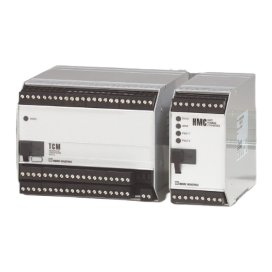
- Page 1 No. 238-713-01K March 2019 Temperature Concentrator System ™ Multi-Channel Transmitter...
-
Page 2: Table Of Contents
Table of Contents Introduction ..................... 5 About this Manual ......................5 Model and Serial Numbers....................5 The TCS ......................5 HART Communications Mode ............... 5 MODBUS RTU Communications Mode ............6 TCM Specifications ..................8 TCM Dimensions ......................10 TCM Terminal Designations ................... 10 Connecting the TCM in HART Mode ................ - Page 3 HART-to-MODBUS Converter ..............28 Installing the HMC Configuration Software ..............28 Connecting the HMC to the PC ..................28 HMC Specifications ..................29 HMC Dimensions ......................30 HMC Terminal Designations ................... 30 Necessary Equipment Table for the HMC ..............31 HMC PC Configuration Software Summary ..........
- Page 4 Installation in Hazardous Locations ............38 Specific conditions of Use ................38 IECEx Installation ..................41 Appendix A:TCS/Stahl I.S. Barrier Configuration ........43 Appendix B:TCS/GMI I.S. Barrier Configuration ........44...
-
Page 5: Introduction
Introduction The TCS System Architecture This manual for Moore Industries’ TCS Temperature A TCS Temperature Concentrator System may consist Concentrator System™ contains all of the information of one or two (when used with an HMC HART-to- needed to configure, install, operate and maintain this MODBUS Converter) 16-channel, loop-powered product. -
Page 6: Modbus Rtu Communications Mode
HMC, using a HART hand-held. The TCM can also be configured, including custom The HMC is configured using Moore Industries’ HMC input linearization, using Moore Industries’ Intelligent Intelligent PC Configuration Software. PC Configuration Software. - Page 7 Temperature Concentrator System™ Multi-Channel Transmitter Figure 5. TCS System Hook-Up Using TX Power TCM 1 STATUS Load = 250 ohms MODBUS Output TEMPERATURE CONCENTRATOR MODULE MODBUS 2 MODBUS 1 –PS TCM 2 To serial (COM) Port of PC INPUT HART...
-
Page 8: Tcm Specifications
Temperature Concentrator System™ Multi-Channel Transmitter TCM Specifications HART Address Range: 0-15 (in Performance Indicators Operating and Storage Digital Input Filter: Specifications HART Communications (continued) Range: -40°C to +85°C 50/60 Hz, Mode) (-40°F to +185°F) User-configurable Transmission Speed: Relative Humidity: Power Supply... - Page 9 Temperature Concentrator System™ Multi-Channel Transmitter Table 4. TCM Input and Accuracy Table α Conformance Minimum Input Maximum Input Type Ohms Range Span Accuracy Range -200 to 850°C ±0.5°C -240 to 960°C 0.003850 -328 to 1562°F ±0.9°F -400 to 1760°F 1000 10°C...
-
Page 10: Tcm Dimensions
Temperature Concentrator System™ Multi-Channel Transmitter Figure 6. TCM Dimensions 131 mm 124 mm [5.17 in] [4.88 in] When Installed 13 mm 47 mm [.53 in] [1.88 in] GROUND SCREW 52 mm [2.06 in] 100 mm [3.94 in] 49 mm [1.96 in] 130 mm [5.15 in]... -
Page 11: Connecting The Tcm In Hart Mode
Temperature Concentrator System™ Multi-Channel Transmitter Figure 8. Connecting the TCM in HART Mode Millivolt Source T/C Simulator Ohms RTD Simulator Refer to Input Wiring STATUS Guide, below, as required for each input TEMPERATURE CONCENTRATOR MODULE –PS 15-42Vdc Power Supply 250 ohm... -
Page 12: Temperature Concentrator Module
Temperature Concentrator Configuring the TCM Module All operating parameters are set using either a HART Communicator or a PC and Moore Industries’ The following section describes use and configuration Intelligent PC Configuration software. of the Temperature Concentrator Module (TCM). Configuration parameters are stored in the The TCM may be used in one of two modes. -
Page 13: Installing The Configuration Software
Connect your instrument to the PC via the RS-232 serial port using the Moore Industries Interface Cable It is not necessary to connect the transmitter to a PC or optional USB cable listed in Table 1. -
Page 14: Tcm Pc Configuration Software Summary
Temperature Concentrator System™ Multi-Channel Transmitter TCM PC Configuration Software Summary Figure 9. TCM PC Configuration Software Main Screen Note: The Mode Setting* must be set before any configuration. This will insure that the correct MODE is active. Mode*– This dropdown menu allows you to select The PC Configuration Software program is made up of TCS or HART mode. -
Page 15: Menu And Tool Bar Legend
Temperature Concentrator System™ Multi-Channel Transmitter Monitor Tab Menu and Tool Bar Legend The first of two tabs in the main window of the TCM Allows New/Open/Save PC Configuration Software Program is the Monitor tab. File and Print functions The Monitor tab displays the individual PV (Process Controls whether Menu and Tool Variable) and channel Status of each channel in use. -
Page 16: Configuration Screens
Temperature Concentrator System™ Multi-Channel Transmitter Configuration Screens Message– Use this area to place a message, or notation for this channel (32 alphanumeric characters, Note: maximum). Unless otherwise noted, ensure that the PC Long Tag–This allows for a longer Tag identifier (up Configuration Program is idle before making any to 32 alphanumeric characters, maximum). - Page 17 Temperature Concentrator System™ Multi-Channel Transmitter Broken Wire Detection– During operation, the TCM Sensor Trimming– Sensor Trimming increases the sends random microamp pulses through input wiring to measurement accuracy of your instrument by matching check for broken wiring or a burned out sensor.
- Page 18 Temperature Concentrator System™ Multi-Channel Transmitter Scaling Tab Custom Curve Tab Figure 12. Scaling Tab Figure 13. Custom Curve Tab Note: Using the Scaling feature will disable the Custom Curve capability. Since both are scaling features used to manipulate the appearance of your process variable, only one of these functions may be used at a time.
-
Page 19: Additional Features
Temperature Concentrator System™ Multi-Channel Transmitter Additonal Features To create a custom curve: This section describes features that are configurable Click the Enabled box. through the Menu and Tool Bar. Select the number of points for your curve (128 points maximum) and enter it into the No Of Points text box. -
Page 20: Using The Hart Communicator
If you are using a Fisher-Rosemount Model 275 or 475 HART Communicator and require the latest version of the DD, you must send the Communicator to Moore Industries. To send the instrument to Moore Industries contact our Customer Service department for a Returned Material Authorization (RMA). - Page 21 Temperature Concentrator System™ Multi-Channel Transmitter Figure 14. TCM HART Communicator Configuration Menu Summary Online Menu 1 Model Configure Sensor Sensor Type 2 Device Setup 3 PV 1 RTD 2 wire 1 Sensor Type 1 PT3850 100 4 LRV 2 RTD 3 wire...
-
Page 22: The Hart Communicator Menu Without A Device Description
Custom curve can only be set using Setup menu parameters are detailed below. Moore Industries’ PC Configuration Software. Input scaling configuration is performed in the Configure Configure Sensor Range menu. - Page 23 Temperature Concentrator System™ Multi-Channel Transmitter Configure Range your scaled LRV (for 0% value). Allowed span is from Within the Configure Range menu are the capabilities -99999 to 99998. to configure Smart Ranging and capture the input. 6 Sensor URV– Enter the sensor’s upper range value 1 Smart Ranging–...
- Page 24 Temperature Concentrator System™ Multi-Channel Transmitter Channel Selection The HART Communicator Allows you to select between TCS or HART mode*. Menu Without a Device If choosing a channel to monitor (Channel 1 through Channel 16), TCS mode is enabled. HART mode is...
- Page 25 Temperature Concentrator System™ Multi-Channel Transmitter Figure 15. Generic HART Communicator Menu Overview Process Variable Online Generic Device Setup 1 Snsr 1 Device Setup 1 Process Variables 2 AI % 2 PV 3 A01 Display 3 PV AO Diag/Service 2 Diag/Service...
-
Page 26: Hart Status Information
Temperature Concentrator System™ Multi-Channel Transmitter HART Status Information Each time the TCM generates a response, frame status information is included in the reply message. The first byte indicates communications errors, if any. Otherwise, if communication was good, this byte may indicate the status of the received command (such as transmitter busy or a command not supported). - Page 27 Temperature Concentrator System™ Multi-Channel Transmitter HART Command 48 The Additional Status Information section in the Channel Info tab displays six additional HARTstatus information bytes in response to HART Command 48–Read Additional HART Status Information. The six data bytes are described in Table 10.
-
Page 28: Hart-To-Modbus Converter
24Vdc power supply and then parameters. connect it to the PC via the RS-232 serial port using the Moore Industries Interface Cable or optional USB TX Power cable listed in Table 11. A transmitter excitation (TX) power supply (26Vdc ±3%@40mA) is standard on the HMC. -
Page 29: Hmc Specifications
Temperature Concentrator System™ Multi-Channel Transmitter HMC Specifications Performance Input Accuracy: Reflects the Performance Alarm Response Time: Indicators LED Type: Dual color accuracy of the TCM Digital Response Time (Continued) red/green indicate: + 150msec, maximum Input Impedance: Transmit INPUT LED: Input is present (defined as the time from Mode: 150 ohms;... -
Page 30: Hmc Dimensions
Temperature Concentrator System™ Multi-Channel Transmitter Figure 16. HMC Dimensions 131mm 138mm WHEN INSTALLED [5.17 in] When Installed (5.43 in) 47mm 133mm WHEN INSTALLED [1.88 in] GROUND (5.24 in) SCREW 126mm 50mm (4.97 in) (1.96 in) 52mm [2.06 in] INPUT HART... -
Page 31: Necessary Equipment Table For The Hmc
Temperature Concentrator System™ Multi-Channel Transmitter Figure 18. HMC Configuration Hook-Up INPUT HART MODBUS CONVERTER READY FAULT 1 24 DC FAULT 2 POWER SUPPLY Table 11. Necessary Equipment Table for the HMC and TCS Device Specifications 24Vdc, ±1.0% (for HMC and TCS) Power Supply 26Vdc, ±1.0% (for Intrinsically-Safe TCM applications only) -
Page 32: Hmc Pc Configuration Software Summary
Temperature Concentrator System™ Multi-Channel Transmitter HMC PC Configuration Software Summary Figure 19. HMC PC Configuration Software Main Screen Once the default configuration has been saved to HMC Device Status– Indicates if there are your PC or external media, it is safe to program other problems or faults with the instrument. -
Page 33: Menu And Tool Bar Legend
Temperature Concentrator System™ Multi-Channel Transmitter HART Tab Menu and Tool Bar Legend Allows New/Open/Save Figure 20. HART Tab File and Print functions Controls whether Menu and Tool Bars are viewed on the screen Allows you to Upload and Download configurations... - Page 34 Temperature Concentrator System™ Multi-Channel Transmitter Alarms Tab MODBUS Tab The information below applies to both TCM1 and Figure 22. MODBUS Tab TCM 2 Alarm sections. Figure 21. Alarms Tab MODBUS Address– The MODBUS Address is the number that the HMC monitor uses to identify itself on the MODBUS network.
-
Page 35: Modbus Rtu Registers
Temperature Concentrator System™ Multi-Channel Transmitter MODBUS RTU Registers Table 12 describes the 30,000 / 40,000 overlapped register set. Please note that MODBUS is limited to reading 32 registers in a single transfer. Table 12. MODBUS 30,000 / 40,000 Register Ranges Table 12. -
Page 36: Installation
Temperature Concentrator System™ Multi-Channel Transmitter Installation • Any Moore Industries product in a metal case or housing should be grounded. Installation consists of physically mounting the unit and completing the electrical connections. • The protective earth conductor must be connected to a system safety earth ground Mounting the TCM and HMC before making other connections. -
Page 37: Operation
Austin, TX 78759-6540 Phone: (512) 794-0369 Fax: (512) 794-3904 www.hartcomm.org Maintenance Moore Industries suggests a quick check for terminal tightness and general unit condition every 6-8 months. Always adhere to any site requirements for programmed maintenance. The Interface Solution Experts... -
Page 38: Installation In Hazardous Locations
Temperature Concentrator System™ Multi-Channel Transmitter Installation in Hazardous Specific Conditions of Use The following instructions must be adhered to when Locations the TCM is used in hazardous ‘Classified’ locations This section contains important information regarding and potentially explosive atmospheres. installation of the TCM in Hazardous Area Locations. - Page 39 Temperature Concentrator System™ Multi-Channel Transmitter Figure 23. TCS System Hook-Up Using an Intinsically-Safe Barrier. See Appendices for specific hook-up diagrams to recommended I.S. barriers WARNING: In an intrinsically-safe system, COM ports cannot be used unless the hazard is completely removed. Therefore, it is suggested that configuration of the TCM and HMC be performed before their placement into a TCS system.
- Page 40 Temperature Concentrator System™ Multi-Channel Transmitter II. Non-Incendive Applications, II. Type “n” Applications Zone 2, Class I & II, Division 2, Class III, ll 3 G Ex nA IIC, Zone 2 Division 1 & 2, Groups A-D 1. If the Model TCM Temperature Concentrator Module is installed as Category 3 equipment, it 1.
-
Page 41: Iecex Installation
Temperature Concentrator System™ Multi-Channel Transmitter IECEx Installations Type “n” Applications Ex nA [nL] IIC, Zone 2 1. If the Model TCM Temperature Concentrator I. Intrinsically Safe Applications Module is installed as Category 3 equipment, it Ex ia IIC, Zones 0, 1 or 2... - Page 42 Temperature Concentrator System™ Multi-Channel Transmitter The Interface Solution Experts...
-
Page 43: Appendix A:tcs/Stahl I.s. Barrier Configuration
Temperature Concentrator System™ Multi-Channel Transmitter The Interface Solution Experts... -
Page 44: Appendix B:tcs/Gmi I.s. Barrier Configuration
Temperature Concentrator System™ Multi-Channel Transmitter Appendix A: TCS/Stahl I.S. Barrier Configuration To use the TCS Temperature Concentrator System in an intrinsically-safe Class I, II, III, Division 1 (Zone 0) hazardous area, an I.S. Barrier such as STAHL Type 9160/13-11-11s (single-channel) or STAHL Type 9160/23-11-11s (dual-channel) can be used as illustrated below. - Page 45 Multi-Channel Transmitter Appendix B: TCS/GMI I.S. Barrier Configuration To use the TCS Temperature Concentrator System in an intrinsically-safe Class I, II, III, Division 1 (Zone 0) hazardous area, an I.S. Barrier such as GMI D1010S (single-channel) or GMI D1010D (dual-channel) can be used as illustrated below.
- Page 46 4. Ship the equipment to the Moore Industries location nearest you. The returned equipment will be inspected and tested at the factory. A Moore Industries rep- resentative will contact the person designated on your documentation if more information is needed.
Need help?
Do you have a question about the Temperature Concentrator System and is the answer not in the manual?
Questions and answers