
Subscribe to Our Youtube Channel
Related Manuals for Moore Industries TRY


Summary of Contents for Moore Industries TRY
- Page 1 & May 2016 Isolated & Non-Isolated 235-701-00H PC-Programmable Temperature Transmitters All product names are registered trademarks of their respective companies.
- Page 2 Most users familiar with a PC and Windows will not have a need for the information in this manual. Moore Industries suggests that if you do need to refer to the information here, rely heavily on the Table of Contents that follow this Quick-Start Guide.
-
Page 3: Table Of Contents
Specifications ............................Input Type & Accuracy ...................... 7 Ordering Information ......................8 Everything You Need is Included ..................8 Configuring a TRY & TRX ....................... What is First ........................9 What is Next ........................9 Installing the Software ....................10 Gathering the Equipment Needed ................. - Page 4 ................... Saving the Configuration Files to Disk ................22 Retrieving a Configuration File from Disk ............... 22 Retrieving a Configuration File from a Connected TRY or TRX ........22 Installing and Connecting the TRY or TRX ..............Physical Dimensions ...................... 24 Connecting the TRY or TRX in an Application..............
-
Page 5: Introduction
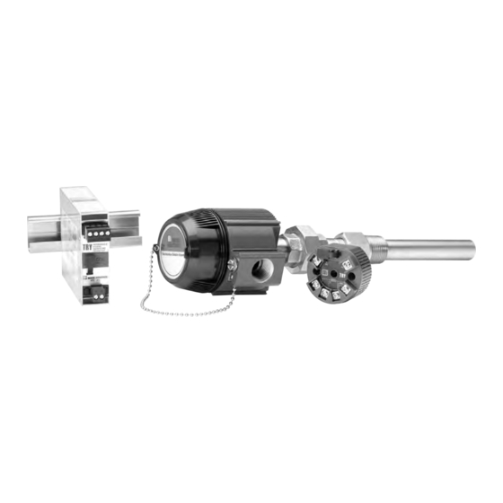
Figure 1. Use the PC-Programmable TRY or TRX as an interface between temperature sensors and control systems such as a DCS, PLC or PC-based control system. Isolated,... -
Page 6: Specifications
RTD Lead Wire Weight HPP-style housing: housing, 1500Vrms input Resistance Maximum: 65g (2.3 oz) to output; For TRY in DIN RTD resistance + 2 times DIN-style housing: housing, 500Vrms input to the lead wire resistance 184g (6.5 oz) output to case... -
Page 7: Input Type & Accuracy
TRY & TRX Table 1. Input Types, Ranges, Minimum Span and Maximum Range Specifications, and Accuracy of the TRY and TRX α ∗ Conformance Minimum Maximum Input Accuracy Input Type Ohms Range Range Span -100 to 560°C ±0.11°C ±0.2°F -50 to 500°C Platinum 0.003750... -
Page 8: Ordering Information
7 compatible). If a problem occurs with a TRY or TRX, check for a tag affixed to the unit listing these numbers. Supply the Customer Support representative with this information when calling. -
Page 9: Configuring A Try/Trx
• Saving the Default Configuration (page 9) No Transmitter Needed (Keeping What You’ve Got Safe) It is not necessary to connect the TRY or TRX to a PC • Selecting Input Type, Wiring Configuration, to create configuration files. The Configuration etc. -
Page 10: Installing The Configuration Software
Configuration Program. the CD drive of the PC. Access the CD and open the “SDY SIY TDY TRX TRY PC Table 2 lists the things needed to setup the TRY or Configuration Software” folder. TRX as shown in Figure 2. -
Page 11: Input Connection Hookups
TRY & TRX Figure 2. Use the PC Configuration Software to program the TRY or TRX. POWER CURRENT SOURCE METER 10-42Vdc 0-50mA – – TRY/TRX COMMUNICATION CABLE 803-040-26 FOR NON-ISOLATED 803-039-26 FOR ISOLATED 208-236-00 USB Cable 804-030-26 Fuse Protected USB Cable –PS... -
Page 12: Pc Configuration Software Summary
TRX. This column will change to reflect the values on options are selected, these scroll bars are renamed to the rest of the screen when you program the TRY or adjust the reverse output and the loop test. TRX with its new values. -
Page 13: Keeping What You've Got Safe-Using The "Get Setup" Function
Configuration Program Main Using “Get Setup” Screen (see Figure 3). Every TRY or TRX is shipped from the factory with a The screen will flicker once, and the settings Configuration File already installed in its memory. This... -
Page 14: Selecting Input Type, Wiring, Etc
Use the selection tools in the Input Type box to choose able only with the “Millivolts” input selection. the sensor type that the TRY or TRX will be reading. Moore Industries suggests saving the initial settings RTD input selections distinguished by the “E” suffixed resident in the transmitter before making any changes alpha value selections use 128-bit linearization curves. -
Page 15: Scaling The Input (Also: Setting Reverse Output)
The instructions assume that the Configuration Settings to your Transmitter” (page 12). Program has been loaded successfully (page 6). To set the scaling for the Input to the TRY or TRX: Start the PC Configuration program and con- Setting Reverse Output nect a transmitter. -
Page 16: Scaling The Output
Select one of these options: Scaling the Output a. Create a Configuration File by setting The TRY or TRX can be configured to scale its different parameters. 4-20mA output to offset the performance or calibration b. Save the current settings into a file on of other instruments in the process loop. -
Page 17: Trimming The Input
Adjust the bath until its temperature settles. Click “Trim Lower” and wait for it to 1. Set all unit parameters on the TRY or TRX Con- capture the value (about 10 seconds). figuration Screen as required for your intended application. -
Page 18: Setting Miscellaneous Functions-Engineering Unit Readout, Input Filtering, Upscale Or Downscale Drive, And Broken Wire Detection
To temporarily disable this feature when readout in the “Status” area of the screen whenever the TRY or TRX is working in a millivolt input configu- the PC is being used to monitor the input from the ration, select the “Broken Wire Off” radio connected sensor. -
Page 19: Setting Output Damping
The higher the damping value (set in seconds), the To use the Loop Test feature, the connected TRY or longer the TRY or TRX will take to respond to trends TRX must stop measuring input. on the input. Click on the “Stop” button. -
Page 20: Creating A Custom Linearization Table
Figure 11. Linearization Must be set to ON to Create a Custom Use the “Restore” button to reset the table to Table. the table stored in the TRY OR TRX’s memory. CAUTION: Restoring the configuration file erases any values in the table, overwriting them with whatever is stored in the most recent file. - Page 21 Values in the “Inp mV” column must be in ascending order and must fall within a range of -50 to 1000 mV. CAUTION: Any time a connected TRY or TRX is “programmed” by downloading a Configuration File into memory, •...
-
Page 22: Managing Configuration Files
Click on the “File” button. This brings up an Retrieving a Configuration File Explorer-like window on the left area of the from the Connected TRY or TRX screen. Make sure a transmitter is connected and communi- Enter the file name that you wish to save in the cating properly with the Configuration Program, then “Selected File Name”... -
Page 23: Installing And Connecting The Try Or Trx
TRY & TRX Printing Saved Configurations The TRY and TRX are available in both DIN and HPP housing styles, and are available with a number of en- Click on the “File” button. This brings up an closure options. Consult your local Moore Industries’... -
Page 24: Physical Dimensions
TRY & TRX Figure 15. The Dimensions of the DIN housing for the TRY or TRX unit. 138mm (5.43 in) 133mm WHEN INSTALLED (5.24 in) WHEN INSTALLED 43mm (1.69 in) 80mm (3.15 in) +PS –PS 110mm 25mm (4.33 in) 113mm (1.0 in) -
Page 25: Operating The Try Or Trx
Some of Moore Industries’ instruments can be classified as receivers (IPT , IPX , etc.) and some can be classified as transmitters (TRX, TRY, etc.) Figure 17. The Dimensions of the explosion-proof housing for the TRY or TRX unit. BOTTOM 87mm 51mm Safety Lock (3.43 in) -
Page 26: Maintaining The Try Or Trx
This condition is “downloadable” to a TRY or TRX. It is intended to provide the user with the ability to monitor general trends on the input, functioning within the rat- ed accuracy whenever input is within the conformance range, but inherently less accurate outside the range. -
Page 27: Appendix A--Intrinsically Safe Diagrams
This page contains the installation diagram for the TRY or TRX carrying the intrinsically safe option. It also includes guidelines for setting up zener barriers necessary in these types of applications. - Page 28 TRY & TRX Demand MOORE Reliability...
- Page 29 4. Ship the equipment to the Moore Industries location nearest you. The returned equipment will be inspected and tested at the factory. A Moore Industries representative will contact the person designated on your documentation if more information is needed. The repaired equipment, or its replacement, will be returned to you in accordance with the shipping instructions furnished in your documentation.
Need help?
Do you have a question about the TRY and is the answer not in the manual?
Questions and answers