Table of Contents

Related Manuals for BIRD Wattcher 3127A


Summary of Contents for BIRD Wattcher 3127A
- Page 1 Wattcher® Monitor/Alarm Models 3126A, 3127A, and 3128A Operation Manual ©Copyright 2017 by Bird Technologies, Inc. Instruction Book Part Number 920-3126/27/28A Rev. C Wattcher is a registered trademark of Bird Electronic Corporation...
-
Page 2: Safety Precautions
Safety Precautions The following are general safety precautions that are not necessarily related to any specific part or procedure, and do not necessarily appear elsewhere in this publication. These precautions must be thoroughly understood and apply to all phases of operation and maintenance. WARNING Keep Away From Live Circuits Operating Personnel must at all times observe general safety precautions. -
Page 3: Safety Symbols
Safety Precautions Safety Symbols WARNING Warning notes call attention to a procedure, which if not correctly performed could result in personal injury. CAUTION Caution notes call attention to a procedure, which if not correctly performed could result in damage to the instrument. This symbol indicates that a shock hazard exists if the precautions in the instruction manual are not followed. -
Page 4: Caution Statements
Wattcher® Monitor/Alarm Caution Statements The following equipment cautions appear in the text whenever the equipment is in danger of damage and are repeated here for emphasis. CAUTION The Wattcher, elements and line section have been calibrated together. Replacing any component without recalibrating all the components as a unit may affect accuracy. See page 5. -
Page 5: Safety Statements
Safety Precautions Safety Statements USAGE ANY USE OF THIS INSTRUMENT IN A MANNER NOT SPECIFIED BY THE MANUFACTURER MAY IMPAIR THE INSTRUMENT’S SAFETY PROTECTION. EL USO DE ESTE INSTRUMENTO DE MANERA NO ESPECIFICADA POR EL FABRICANTE, PUEDE ANULAR LA PROTECCIÓN DE SEGURIDAD DEL INSTRUMENTO. BENUTZUNG WIRD DAS GERÄT AUF ANDERE WEISE VERWENDET ALS VOM HERSTELLER BESCHRIEBEN, KANN DIE GERÄTESICHERHEIT BEEINTRÄCHTIGT WERDEN. - Page 6 Wattcher® Monitor/Alarm SERVICE SERVICING INSTRUCTIONS ARE FOR USE BY SERVICE - TRAINED PERSONNEL ONLY. TO AVOID DANGEROUS ELECTRIC SHOCK, DO NOT PERFORM ANY SERVICING UNLESS QUALIFIED TO DO SERVICIO LAS INSTRUCCIONES DE SERVICIO SON PARA USO EXCLUSIVO DEL PERSONAL DE SERVICIO CAPACITADO.
- Page 7 Safety Precautions CONNECT INTERLOCK TO TRANSMITTER BEFORE OPERATING. BRANCHER LE VERROUILLAGE À L'ÉMETTEUR AVANT EMPLOI. CONECTE EL INTERBLOQUEO AL TRANSMISOR ANTES DE LA OPERACION. VOR INBETRIEBNAHME VERRIEGELUNG AM SENDER ANSCHLIESSEN. PRIMA DI METTERE IN FUNZIONE L'APPARECCHIO, COLLEGARE IL DISPOSITIVO DI BLOCCO AL TRASMETTITORE.
-
Page 8: About This Manual
Wattcher® Monitor/Alarm About This Manual This manual covers the operating and maintenance instructions for the following models: 3126A 3127A 3128A Changes to this Manual We have made every effort to ensure this manual is accurate. If you discover any errors, or if you have suggestions for improving this manual, please send your comments to our Solon, Ohio factory. -
Page 9: Table Of Contents
Table of Contents Safety Precautions ..............i Safety Symbols . - Page 10 Wattcher® Monitor/Alarm Alarm Condition ................10 Determining VSWR .
-
Page 11: Chapter 1 Introduction
The information in this instruction book pertains to all models except noted differences referred to in the text. The Bird Wattcher RF Monitor/Alarm—when installed with a dual port Thruline Line Section and two elements—is designed for the protection and monitoring of radio frequency transmission systems. The line section is selected to be compatible with the RF coaxial line used in the transmission system. -
Page 12: Items Supplied
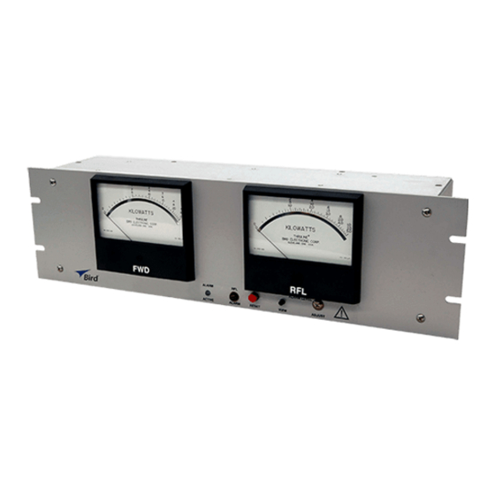
Wattcher® Monitor/Alarm Items Supplied Wattcher Monitor/Alarm 115/230 VAC Power Cord DC Cable (2)—25’ Standard Other Lengths Optional Interlock Connector—Six-Terminal, Screw-Clamp Plug Connector Remote Reset / Auxiliary DC Connector—Four-Terminal Screw-Clamp Plug Connector Options Line Sections & Elements Frequency and power range are governed by the line section and elements selected. - Page 13 Introduction Table 1 Front Panel Forward Power Meter Analog Meter Indicating forward power. Reflected Meter Analog Meter indicating reflected power. Adjust Potentiometer providing for adjustment of reflected power trip level. View Push-button Allows for viewing the reflected power trip level during adjustment.
-
Page 14: Chapter 2 Theory Of Operation
Chapter 2 Theory of Operation General The forward power meter acts as a continuous monitor of forward power output. This provides a reference against the reflected power value enabling determination of power ratios and VSWR. Alarm Condition An alarm condition occurs as the result of the reflected power being greater than the reflected power set point for longer than 50ms. -
Page 15: Element Socket
Theory of Operation The reflected wave originates by reflection at the load, travels, and its power flows from the load back to the source. It has an RF voltage E and current I in phase, with E Note that each component wave is mathematically simple and is completely described by a single figure for power, for instance: ... -
Page 16: R Vs. F And Its Significance
Wattcher® Monitor/Alarm Where appreciable power is reflected, as with an antenna, it is necessary to subtract the reflected power from the forward power to get the effective power. This correction is negligible, less than 1 percent, if the loading device has a VSWR of 1.2 to 1 or less. -
Page 17: Chapter 3 Installation
The Wattcher Unit model and serial numbers are located on the back panel. Before proceeding with the installation record these numbers in the space provided on the last page of this manual. The model and serials numbers will be required when obtaining information from the Factory or Bird’s customer service department. Line Section A coupling kit is required for connecting the line section to the transmission line. -
Page 18: Wattcher Rf Monitor/Alarm
Wattcher® Monitor/Alarm Figure 5 Coupling Connections Wattcher RF Monitor/Alarm The Wattcher is designed to mount in an EIA standard 19" relay rack. Wire lengths are not critical, the unit may be installed where convenient for monitoring and operation. The following connections and switch settings should be made before installation. -
Page 19: Chapter 4 Operating Instructions
Chapter 4 Operating Instructions General This section contains information about the various operating modes and features of the Wattcher RF Monitor/ Alarm. Zero Adjust The two panel meters should be checked for zero set under no power conditions. With no power applied the meter pointers should set exactly on zero. -
Page 20: Using Remote Reset & Auxiliary Dc
Wattcher® Monitor/Alarm Figure 7 Interlock Connector Using Remote Reset & Auxiliary DC Remote reset can be used to wire a reset switch in a convenient location. Actuating the switch will reset the alarm condition after the error has been corrected. The reset input can be jumpered to ground so that the alarm will clear automatically when the reflected power drops below the set point. - Page 21 Operating Instructions Figure 9 VSWR Conversion Nomograph...
- Page 22 Wattcher® Monitor/Alarm Figure 10 VSWR Conversion Nomograph...
-
Page 23: Chapter 5 Maintenance
Chapter 5 Maintenance Preparation for Shipment Elements The elements can be left in the sockets of the line section with their ARROWS turned midway between the measuring positions. Any additional elements should be well padded and wrapped before being put in the shipping container. -
Page 24: Troubleshooting
Wattcher® Monitor/Alarm Troubleshooting The following table contains troubleshooting information for problems which can occur during normal operation. Locate the problem, review the possible cause, and perform the corrective action listed. Only those functions within the scope of normal maintenance are listed. This manual cannot list all malfunctions that may occur, or all corrective actions. -
Page 25: Customer Service
Any maintenance or service procedure beyond the scope of those in this chapter should be referred to a qualified service center. If the unit needs to be returned for any reason, request an Return Material Authorization (RMA) through the Bird Technologies website. All instruments returned must be shipped prepaid and to the attention of the RMA number. -
Page 26: Cleaning
Wattcher® Monitor/Alarm Cleaning WARNING When using dry cleaning solvents, provide adequate ventilation and observe normal safety precautions. Many dry cleaning agents emit toxic fumes that may be harmful to your health, if inhaled. If any of the contacts or line connectors become dirty, they should be wiped off with a clean cloth and a dry cleaning solvent. -
Page 27: Meter Replacement
Maintenance Meter Replacement CAUTION Do not attempt to check the microammeters with an ohmmeter. Damage to the movement or pointer will result. Disassembly 1. Remove four screws securing the front panel. 2. Pull front panel forward until it clears the lamps and switches. 3. -
Page 28: Specifications
Wattcher® Monitor/Alarm Specifications Models 3126A and 3127A 100W to 250 kW using Bird plug-in Power Range elements Frequency Range 2 to 1000 MHz ±5% of full scale (for elements Accuracy calibrated with the Wattcher) Meter Scales FWD 15/30/60 kW 3126A RFL 1.5/3/6 kW... -
Page 29: Replacement Parts List
Maintenance Replacement Parts List Qty. Description Part Number BR1, Rectifier, full wave silicone bridge 5-1661 LS1, Buzzer, alarm 5-1714 F1 - F2, Fuse .125A at 250 VAC 5A2257-7 LS1, Fuse holder, alarm 5A2295-1 K1, Power relay, 3pdt 5A2116-1 M2, Meter, triple scale, incident power 2150-259 - Model 3126A, 100uA 15/30/60kW scale 2150-230... -
Page 30: Available Qc Type Connectors
Wattcher® Monitor/Alarm Available QC Type Connectors “ line section equipped with quick change “QC” connectors. Note: When selecting “QC” connectors, consideration must be given to frequency and power range capability of size of connector. N-Female 4240-062 BNC-Male 4240-132 N-Male 4240-063 LT-Female 4240-018 HN-Female... -
Page 31: Limited Warranty
Limited Warranty All products manufactured by Seller are warranted to be free from defects in material and workmanship for a period of one (1) year, unless otherwise specified, from date of shipment and to conform to applicable specifica- tions, drawings, blueprints and/or samples. Seller’s sole obligation under these warranties shall be to issue credit, repair or replace any item or part thereof which is proved to be other than as warranted;...
Need help?
Do you have a question about the Wattcher 3127A and is the answer not in the manual?
Questions and answers