Table of Contents
Advertisement
Quick Links
Advertisement
Table of Contents

Related Manuals for BIRD WATTCHER 3126A


Summary of Contents for BIRD WATTCHER 3126A
- Page 1 INSTRUCTION BOOK OPERATING INSTRUCTIONS WITH PARTS LIST WATTCHER® MONITOR/ALARM MODELS 3126A, 3127A, & 3128A © Copyright 1996 by Bird Electronic Corporation Instruction Book Part Number 920-3126/27/28A Revision A Thruline® and Wattcher® are registered trademarks of Bird Electronic Corporation...
- Page 2 LIMITED WARRANTY All products manufactured by Seller are warranted to be free from defects in material and workmanship for a period of one (1) year, unless otherwise specified, from date of shipment and to conform to applicable specifications, drawings, blueprints and/or samples. Seller’s sole obligation under these warranties shall be to issue credit, repair or replace any item or part thereof which is proved to be other than as warranted;...
-
Page 3: Safety Precautions
Safety Precautions The following are general safety precautions that are not necessarily related to any specific part or procedure and do not necessarily appear elsewhere in this publication. These precautions must be thoroughly understood and apply to all phases of operation and maintenance. Keep Away From Live Circuits Operating personnel must at all times observe general safety precautions. -
Page 4: Warning Statements
Bird Models 3126A, 3127A, 3128A Wattcher RF Monitor/Alarm 3126A/27A/28A Warning Statements The following safety warnings appear in the text where there is danger to operating and maintenance personnel and are repeated here for emphasis. WARNING Electrical shock hazard. Disconnect from ac power source before servicing. -
Page 5: About This Manual
About This Manual This instruction manual covers the Wattcher RF Monitor/Alarm models 3126A, 3127A, and 3128A. This instruction book is arranged so that essential information on safety is contained in the front of the book. Reading the Safety Precautions Section before operating the equipment is strongly advised. The remainder of this Instruction Book is divided into Chapters and Sections. -
Page 6: Table Of Contents
Table of Contents Safety Precautions ............3 Keep Away From Live Circuits . -
Page 7: Chapter 1 - Introduction
The information in this instruction book pertains to all models except noted differences referred to in the text. The Bird Wattcher RF Monitor/Alarm—when installed with a dual port Thruline Line Section and two elements—is designed for the protection and monitoring of radio frequency transmission systems. -
Page 8: Specifications
Bird Models 3126A, 3127A, 3128A Wattcher RF Monitor/Alarm Specifications Models 3126A and 3127A Power Range: 100W to 250 kW using Bird plug-in elements Frequency Range: 2 to 1000 MHz Accuracy: ±5% of full scale (for elements calibrated with the Wattcher) -
Page 9: Functional Description
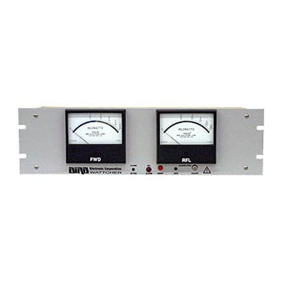
Chapter 1 - Introduction Functional Description The Wattcher RF Monitor/Alarm is enclosed in an aluminum housing intended for a standard 19" Enclosure rack mount. Figure 2 Front Panel Front Panel Analog Meter Indicating forward power. Forward Power Meter Analog Meter indicating reflected power. Reflected Meter Green LED, when illuminated the alarm is active, power is on. -
Page 10: Rear Panel
Bird Models 3126A, 3127A, 3128A Wattcher RF Monitor/Alarm Figure 3 Back Panel Rear Panel Forward Sensor Input connector for forward power sensor cable from port A of line section. Input Connector Reflected Sensor Input connector for reflected power sensor cable from port B of line section. -
Page 11: Chapter 2 - Theory Of Operation
Chapter 2 - Theory of Operation The forward power meter acts as a continuous monitor of forward power output. This provides General a reference against the reflected power value enabling determination of power ratios and VSWR. An alarm condition occurs as the result of the reflected power being greater than the reflected Alarm Condition power set point for longer than 50ms. - Page 12 Bird Models 3126A, 3127A, 3128A Wattcher RF Monitor/Alarm The forward wave travels and its power flows from the source to the load. It has an RF voltage and current I in phase, with E The reflected wave originates by reflection at the load, travels, and its power flows from the load back to the source.
- Page 13 Chapter 2 - Theory of Operation Where appreciable power is reflected, as with an antenna, it is necessary to subtract the reflected power from the forward power to get the effective power. This correction is negligible, less than 1 percent, if the loading device has a VSWR of 1.2 to 1 or less. VSWR scales, and their attendant controls for setting the reference point, have been intentionally omitted from the Thruline Wattmeter for two reasons.
- Page 14 Bird Models 3126A, 3127A, 3128A Wattcher RF Monitor/Alarm...
-
Page 15: Chapter 3 - Installation
The model and serials numbers will be required when obtaining information from the Factory or Bird’s customer service department. A coupling kit is required for connecting the line section to the transmission line. The coupling Line Section kit will be similar to one of the coupling kits shown below. - Page 16 Bird Models 3126A, 3127A, 3128A Wattcher RF Monitor/Alarm Wattcher RF The Wattcher is designed to mount in an EIA standard 19" relay rack. Wire lengths are not Monitor/Alarm critical, the unit may be installed where convenient for monitoring and operation.
-
Page 17: Chapter 4 - Operations
Chapter 4 - Operations General This section contains information about the various operating modes and features of the Wattcher RF Monitor/Alarm. Zero Adjust The two panel meters should be checked for zero set under no power conditions. With no power applied the meter pointers should set exactly on zero. -
Page 18: Using Remote Reset & Auxiliary Dc
Bird Models 3126A, 3127A, 3128A Wattcher RF Monitor/Alarm Using Remote Reset & Auxiliary DC Remote reset can be used to wire a reset switch in a convenient location. Actuating the switch will reset the alarm condition after the error has been corrected. -
Page 19: Vswr Conversion Nomographs
Chapter 4 - Operations VSWR Conversion Nomograph... - Page 20 VSWR Conversion Nomograph...
-
Page 21: Chapter 5 - Maintenance
Chapter 5 - Maintenance Any maintenance or service procedure beyond the scope of those provided in this section should be referred to a qualified service center. Bird Electronic Corporation maintains complete repair and calibration facilities at the following address: Bird Electronic Corporation... -
Page 22: Troubleshooting
Bird Models 3126A, 3127A, 3128A Wattcher RF Monitor/Alarm Troubleshooting The following table contains troubleshooting information for problems which can occur during normal operation. Locate the problem, review the possible cause, and perform the corrective action listed. Only those functions within the scope of normal maintenance are listed. This manual cannot list all malfunctions that may occur, or all corrective actions. -
Page 23: Cleaning
Chapter 5 - Maintenance Cleaning WARNING When using dry cleaning solvents, provide adequate ventilation and observe normal safety precautions. Many dry cleaning agents emit toxic fumes that may be harmful to your health, if inhaled. If any of the contacts or line connectors become dirty, they should be wiped off with a clean cloth and a dry cleaning solvent. -
Page 24: Meter Replacement
Bird Models 3126A, 3127A, 3128A Wattcher RF Monitor/Alarm Meter Replacement Caution Do not attempt to check the microammeters with an ohmmeter. Damage to the movement or pointer will result. 1. Remove four screws securing the front panel. Disassembly 2. Pull front panel forward until it clears the lamps and switches. -
Page 25: Replacement Parts
Chapter 5 - Maintenance Replacement Parts Qty. Description Part Number BR1, Rectifier, full wave silicone bridge 5-1661 LS1, Buzzer, alarm 5-1714 F1 - F2, Fuse .125A at 250 Vac 5A2257-7 LS1, Fuse holder, alarm 5A2295-1 K1, Power relay, 3pdt 5A2116-1 M2, Meter, triple scale, incident power Model 3126, 100uA 15/30/60kW scale 2150-259... - Page 26 Bird Models 3126A, 3127A, 3128A Wattcher RF Monitor/Alarm Record model and serial numbers located on back panel. MODEL NUMBER SERIAL NUMBER...
Need help?
Do you have a question about the WATTCHER 3126A and is the answer not in the manual?
Questions and answers