
Related Manuals for BIRD IQC5000B


Summary of Contents for BIRD IQC5000B
- Page 1 IQC5000B RF Signal Record and Playback System Operation Manual © Copyright 2019 by Bird Technologies Inc. Instruction Book Part Number 920-IQC5000 Rev. P6...
-
Page 2: Safety Precautions
IQC 5000B Operation Manual Safety Precautions The IQC5000 consists of complex precision RF test equipment and electronic hardware. Care should be taken in handling the equipment to limit shock and vibration. This equipment is not considered user serviceable, and should only be modified or serviced by qualified personnel. - Page 3 Safety Precautions WARNING Take Proper ESD Measures Handling of electrostatic discharge-sensitive devices is to be done within an approved ESD workstation, using appropriate grounding equipment. Compliance to proper ESD protocol is essential. Safety Symbols WARNING Warning notes call attention to a procedure, which if not correctly performed, could result in personal injury.
-
Page 4: Caution Statements
IQC 5000B Operation Manual Caution Statements The IQC5000 consists of complex precision RF test equipment and electronic hardware. Care should be taken in handling the equipment to limit shock and vibration. This equipment is not considered user serviceable, and should only be modified or serviced by qualified personnel. -
Page 5: Safety Statements
Safety Precautions Safety Statements USAGE ANY USE OF THIS INSTRUMENT IN A MANNER NOT SPECIFIED BY THE MANUFACTURER MAY IMPAIR THE INSTRUMENT’S SAFETY PROTECTION. EL USO DE ESTE INSTRUMENTO DE MANERA NO ESPECIFICADA POR EL FABRICANTE, PUEDE ANULAR LA PROTECCIÓN DE SEGURIDAD DEL INSTRUMENTO. BENUTZUNG WIRD DAS GERÄT AUF ANDERE WEISE VERWENDET ALS VOM HERSTELLER BESCHRIEBEN, KANN DIE GERÄTESICHERHEIT BEEINTRÄCHTIGT WERDEN. - Page 6 IQC 5000B Operation Manual SERVICE SERVICING INSTRUCTIONS ARE FOR USE BY SERVICE - TRAINED PERSONNEL ONLY. TO AVOID DANGEROUS ELECTRIC SHOCK, DO NOT PERFORM ANY SERVICING UNLESS QUALIFIED TO DO SO. SERVICIO LAS INSTRUCCIONES DE SERVICIO SON PARA USO EXCLUSIVO DEL PERSONAL DE SERVICIO CAPACITADO.
-
Page 7: About This Manual
When inquiring about updates to this manual refer to the part number and revision on the title page. Chapter Layout Introduction — Describes the features of the IQC5000B RF Recorder, lists equipment supplied and optional equipment. IQC5000 Controls and Indicators —... -
Page 8: Table Of Contents
Table of Contents Safety Precautions ..............i General Safety Precautions . - Page 9 Managing IQC5000B-MEM External Storage ........
- Page 10 Restoring Functionality on the IQC5000B & IQC5000B-MEM ........
- Page 11 Table of Contents RF Outputs ................89 General Specifications .
-
Page 12: Chapter 1 Introduction
RAID 0 operation. Signals are stored in a non-proprietary format to allow analysis by a wide range of digital signal processing tools. The Bird Computer Workstation and Bird’s Spectro-X software, provide users a very powerful turn-key digital signal processing capability. -
Page 13: Available Equipment
Introduction The IQC5000B is capable of I/Q baseband and RF playback. The I/Q Baseband playback is intended for normal use, RF playback capability should be used for testing and system validation only. Do not use RF Playback for normal use. - Page 14 IQC 5000B Operation Manual Option Description IQC5000B-GPS GPS/IRIG-B Timing Standard, includes GPS antenna and interface cable. IQC5000B-RSX Adapter for Rohde & Schwarz EX-IQ rev 04 interface box. Only compatible with EX-IQ boxes with serial numbers above 102000. Playback IQC5000B-101 Adds single playback channel to support up to 160 MHz; Baseband I & Q (2ea SMA female) and RF Out at 2.4 GHz, 0dBm (1ea SMA female).
-
Page 15: Compatible Spectrum Analyzers
Introduction Compatible Spectrum Analyzers The IQC5000 is capable of recording digital I/Q data from the following Spectrum Analyzers: Table 4 - Compatible Spectrum Analyzers Vendor Compatible Spectrum Analyzer Supported Acq BW N9040B - No Options 19.531 kHz to 10 MHz N9040B with Option B25 19.531 kHz to 25 MHz N9040B with Option B40... - Page 16 IQC 5000B Operation Manual Vendor Compatible Spectrum Analyzer Supported Acq BW MS2090A wit Option 124 and Option 125 and 36kHz to 20MHz, discrete† MA25424A IQ Converter MS2090A wit Option 124 and Option 125 and Option 103 and 36kHz to 50MHz, discrete† MA25424A IQ Converter Anritsu MS2090A wit Option 124 and Option 125 and Option 104 and...
-
Page 17: Iqc5000 Controls And Indicators
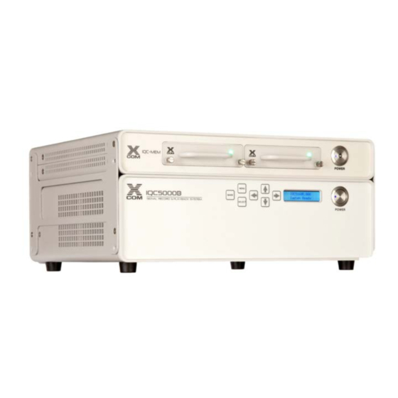
160 MHz bandwidth. Power Pushbutton Used to apply and remove power to the IQC-MEM unit. Power Pushbutton Used to apply and remove power to the IQC5000B. Front Panel Display Displays current mode and menu. Directional Arrows Used for navigating the front panel menus. - Page 18 DC input power (12 VDC) SMA (Jack) Local Oscillator In/Out 4-Lane PCIe PCI Express interface - not used on IQC5000B Ext. MiniSAS HD Cable connection for IQC-MEM unit. Record directly to external storage Power Jack DC input power (10-14 VDC)
-
Page 19: Chapter 2 Setup
Chapter 2 Setup Hardware Setup – Record Figure 4 Recording Hardware Setup To set up the hardware for recording: 1. Connect the Power Cables to the following devices: IQC5000 (Note: requires 10-14V power adapter) b. Spectrum Analyzer (SA) Ethernet Switch d. - Page 20 Connect the External MiniSAS HD to External MiniSAS HD cable to the IQC5000B to MEM port – with tab facing down – connect remaining end to the IQC-MEM to IQC port – with tab facing up.
- Page 21 Setup Figure 6 IQC-MEM External Storage Cable Connections (Option: 2-channel recording with ONE external SSD storage unit) Connect one end of the External MiniSAS HD cable to IQC-MEM EXT STORAGE PORT 2, and the remaining end of the cable to the Exter- nal Storage Unit data port.
- Page 22 IQC 5000B Operation Manual 7. (Option) Connect the Time/Location Cables: (Option: for time/location-tagging) Connect a NMEA GPS source to the NMEA GPS input on the IQC5000. See "NMEA GPS Port Baud Rate Selection" on page 48. b. (Option: for precision time-tagging) Connect an IRIG-B122 source to the IRIG-B input on the IQC5000. 8.
-
Page 23: Hardware Setup - Playback
Hardware Setup – Playback The IQC5000B is capable of I/Q baseband and RF playback. The I/Q Baseband playback is intended for normal use, RF playback capability should be used for testing and system validation only. Do not use RF Playback for normal use. - Page 24 IQC 5000B Operation Manual Figure 8 IQC-MEM Cable Connection b. Connect one end of the External MiniSAS HD cable to the IQC-MEM EXT STORAGE PORT 1, connect the remaining end to External Storage Unit 1 data port. Figure 9 IQC-MEM External Storage Cable Connections (Option: 2-channel recording with ONE external SSD storage unit) Connect one end of the External MiniSAS HD cable to IQC-MEM EXT STORAGE PORT 2, and the remaining end of the cable to the Exter- nal Storage Unit data port.
- Page 25 Setup CAUTION RF Connector Torque Ratings When mating RF connectors, ensure that they are properly aligned and not cross- threaded. Additionally, do not under/over torque RF connectors, as this could result in unreliable results, or worse, damaging the IQC5000. Always check manufacturer specification for proper torque ratings of all RF connectors.
-
Page 26: Network Setup
1. For any firewall devices that may limit network port usage, white list the ports/protocols in Table 7. Table 7 - Listening Ports and Protocols Device Listening Device Type Vendor Device/Software Port, Protocol Record/Playback System Bird IQC5000 6644, TCP & UDP Computer Workstation Bird IQC Control SCPI Command Server 6634, TCP & UDP N9010A/B... -
Page 27: Keysight X-Series Spectrum Analyzer Setup
Setup Keysight X-Series Spectrum Analyzer Setup Note: Refer to the X-Series Operating Manual for more detailed instructions on signal analyzer opera- tion. The following represents the minimum steps required to perform a recording with the IQC5000. Setting the IP Address Setting the IP address on an X-Series spectrum analyzer follows the standard method of setting an IP address in Microsoft®... -
Page 28: Keysight Operation
PC. The Keysight analyzers also include x4 PCIeGen2 interface allowing IQ data to be offloaded from the IQC5000B into the internal PC of the X-Series analyzer. Note: Optionally, an external USB 3.0 drive may be used to offload data to or from the analyzer... -
Page 29: Rohde And Schwarz Fsv/Fsw
Setup Rohde and Schwarz FSV/FSW Note: Refer to the FSV or FSW Operating Manual for more detailed instructions on signal analyzer opera- tion. The following represents the minimum steps required to perform a recording with the IQC5000. Setting the IP Address To set the IP address of the FSV/FSW: 1. - Page 30 IQC 5000B Operation Manual Figure 13 DigIConf Setup Diagram No further configuration of DigIConf is required. The IQC Control software will automatically configure the rest.
-
Page 31: Tektronix Rsa6000 Series
Setup Tektronix RSA6000 Series Note: Refer to the Tektronix RSA6000B Operating Manual for more detailed instructions. The following steps are intended to provide a quick setup of record-specific settings. It is recommended that a saved setup be made after completing the necessary steps for recording. A saved setup file can be set to a user preset, so that the setup can be quickly recalled. -
Page 32: Connection Points
IQC 5000B Operation Manual Connection Points This section describes the input and output connectors on the Tektronix RSA6000 spectrum analyzer. For more information on the spectrum analyzer, reference the Tektronix RSA Operating Manual. Figure 15 Tektronix RSA Front Panel The following is a description of the front-panel controls on the RSA. Table 8 - Tektronix RSA Front Panel Connectors Item... - Page 33 Setup Figure 16 Tektronix RSA Rear Panel The following is a description of the rear-panel connection points on the RSA. Table 9 - Tektronix RSA Rear Panel Connectors Item Description AC Input, main power connector GPIB PS2 Keyboard input Real Time IQ Out (Option 05) Microphone in;...
-
Page 34: Setting The Ip Address
IQC 5000B Operation Manual Setting the IP Address Setting the IP address on the RSA follows the standard method of setting an IP address in Microsoft® Windows Vista™ or Microsoft® Windows 7™, depending on the operating system installed on the RSA. Set the IP address as outlined in "Network Setup"... -
Page 35: Enable Dpx Display
Setup 2. Select the Run alignments only when “Align Now” button is pressed option. 3. Select Align Now to perform alignment. Figure 19 Alignments Dialog Box Enable DPX Display The DPX display must be enabled to record data from the RSA. It is recommended that only the DPX display is enabled during recording to minimize processing conflict. -
Page 36: Anritsu Field Master Pro Ms2090A
Refer to the Anritsu Field Master Pro MS2090A User Guide for detailed instructions on setup and configuration of the MS2090A. The control software for the IQC5000B, IQC Control, controls the IQ streaming operation via the Ethernet connection to the MS2090A. -
Page 37: Chapter 3 Operating Instructions
Chapter 3 Operating Instructions Starting and Stopping the System Some of the devices within the IQC5000 system setup must be connected and powered on and off in a certain order. All steps that must be performed in a particular order are noted below: Note: When using the PCIe cable connection between the IQC5000 and the Computer Workstation, the IQC5000 must be powered on before the Computer Workstation is powered on, and it must be powered off after the Computer Workstation is powered off. -
Page 38: Setting The Sample Rate Selection
Storage Media/Controllers IQC5000B-MEM Module: The IQC-MEM is a storage controller capable of writing to internal removable SSD RAID storage units, or to external RAID0 storage units. External Storage: Enclosure containing disk drives formatted with industry-standard RAID0 striping to increase write speed. -
Page 39: Controlling The Iqc5000
IQC5000 and connected devices using a SCPI-like lan- guage. See the IQC5000 API Programming Manual. Record (Capture, Acquisition) IQC5000B Storage The IQC5000B-MEM module supports reading/writing to external storage as well as reading/writing to internal, removable drive cartridges. Table 10 - IQC5000B-MEM Supported Storage Options... -
Page 40: Steps To Record
IQC 5000B Operation Manual Steps to Record The high-level steps to record with the IQC5000 are: 1. Set up the hardware - follow steps in "Hardware Setup – Record" on page 8. 2. Set up the network - follow steps in "Network Setup" on page 15. 3. -
Page 41: Acquisition Bandwidth
Operating Instructions Following is a brief description of the possible record start/stop methods: Immediate (Manual) (start and/or stop) – starts/stops a recording immediately on user input. Time of day (start and/or stop) – starts/stops a recording at a specified time of day. ... - Page 42 IQC 5000B Operation Manual Table 13 - Tektronix RSA5000B Discrete Acquisition Bandwidths Supported by the IQC5000 I/Q Sampling Data Rate RSA5000B Acq SR/Acq BW Highest Option Rate (Sps) (Bytes/s) BW (Hz) Divisor Required 200,000,000 800,000,000 165,000,000 1.2121 B16X or B16XHD 200,000,000 800,000,000 85,000,000...
- Page 43 Operating Instructions Table 15 - Anritsu MS2090A Acquisition Bandwidths Supported by the IQC5000 Highest Option Required I/Q Sampling Data Rate MS2090A SR/Acq BW Real Time Spectrum Rate (Sps) (Bytes/s) Acq BW (Hz) Divisor Spectrum Analyzer Mode Analyzer Mode Option 199 and 200000000 800000000 110000000...
-
Page 44: Playback
Playback The IQC5000B is capable of I/Q baseband and RF playback. The I/Q Baseband playback is intended for normal use, RF playback capability should be used for testing and system validation only. Do not use RF Playback for normal use. - Page 45 Operating Instructions Table 17 - IQC5000 Supported Playback Acquisition Bandwidth- Rohde & Schwarz Rohde & Schwarz Recording Spans (Hz) I/Q Sampling Rate Data Rate (Sps) (Bytes/s) FSV/ FSVR 300,000,000 down to 40,000,000 160,000,000 4x IQ 31,250,000 in any step down to down to Sampling supported by the signal...
-
Page 46: Markers
IQC 5000B Operation Manual Table 19 - IQC5000 Supported Playback Acquisition Bandwidth- Anritsu Anritsu I/Q Sampling Rate Data Rate Recording Spans (Sps) (Bytes/s) (Hz) 200,000,000 down to 110,000,000 down to 31,250,000 in any strip 4x IQ Sampling 25,000,000 supported but the spectrum Rate analyzer 25,000,000... -
Page 47: File Transfer
Figure 22 NMEA Data Input NMEA custom cables are available from Bird. The 1PPS signal may be optionally connected to the Marker 1 SMA port to insert a marker every second. The baud rate for the NMEA GRPS input (DB9) is selectable. See"NMEA GPS Port Baud Rate Selection" on page 48. -
Page 48: Chapter 4 Using Iqc5000 With Iqc Control
Chapter 4 Using IQC5000 with IQC Control The IQC5000 is controlled through IQC Control. An API is available for controlling the IQC5000, and is detailed in the IQC5000 API Programming Manual. The following sections detail IQC Control’s Graphical User Interface. Installing the IQC Control Software and Loading the IQC5000 Firmware On the IQC5000 software CD shipped with the product, access the file IQC5000_setup_vW.X.Y.ZZZ.exe, where W.X.Y.ZZZ represents the version number of the installer. - Page 49 Using IQC5000 with IQC Control Figure 23 IQC Control Setup Wizard 7. Choose the installation directory and then click Install. Figure 24 IQC Control Directory Selection 8. The firmware update message box will display: Enter the IP address of your IQC5000 in the IP Address text box and click the Connect button. Alternatively, if the device has previously been added as a tab in IQC Control select the device from the list at the bottom of the window.
- Page 50 Firmware that has been detected as requiring an update will be pre-selected. Click Commence Update. The progress of the firmware installation is displayed. Note: It is not recommended to manually overwrite firmware unless instructed to do so by Bird support.
- Page 51 Using IQC5000 with IQC Control Figure 26 IQC5000 Firmware Update Sequence After the firmware installation process has finished, click OK to close the firmware installation. Power off the IQC5000: If IQC-MEM is being used, the IQC-MEM module should be powered off first. Power off the IQC5000.
-
Page 52: Installing The Pcie Driver
IQC 5000B Operation Manual Installing the PCIe Driver With all of the equipment powered down, ensure the Ethernet and PCIe connections are made as described in Chapter 2 "Setup" on page 8. To install or update the PCIe driver: 1. Power on the control computer or real time spectrum analyzer where IQC Control is or will be installed, but leave the IQC and MEM(s) powered off. -
Page 53: Starting Iqc Control
Using IQC5000 with IQC Control Starting IQC Control Shortcuts on the desktop and Start menu are created when IQC Control is installed. To access the Start menu shortcut, navigate to Start > All Programs > X-COM > X-COM Control > X-COM Control. Adding an IQC5000 to IQC Control The IQC5000 is added as a device in IQC Control and can be accessed as a tab on the main user interface or in a separate window. -
Page 54: The Iqc5000 Control Tab Layout And Visual Components
System tab is used to select and configure RAIDs, set maximum record file size, set NMEA GPS baud rate, and monitor system temperatures. See “Managing IQC5000B-MEM External Storage” on page 46. Record tab is used to select input channels, enable marker inputs, select recording type and view presence of external input signals. -
Page 55: Progress Bar
Using IQC5000 with IQC Control Progress Bar The progress bar is located near the top of the IQC5000 Management section. It displays the state of the IQC5000 – such as Idle when it is not performing any action – and the progress of the current operation (such as record, playback, or erase). -
Page 56: Connecting To The Iqc5000
IQC 5000B Operation Manual Connecting to the IQC5000 Establishing Connection Press the Connect button to connect to the IQC5000. Figure 34 IQC5000 Connection Establishing the connection triggers a quick and simple automated process that runs through a series of verification procedures in order to ensure optimal device connectivity and operation. -
Page 57: Disconnecting
At any time during normal operation, the device may be disconnected in order to shut down IQC Control, or to allow operation from another workstation. Managing IQC5000B-MEM External Storage If an IQC-MEM module is being used to record data to external storage units, the RAID Selection settings will be configurable. -
Page 58: Selecting A Raid For Use
IQC 5000B Operation Manual Figure 38 RAID Assembly Unused disks not currently assembled in a RAID are listed on the left under Available Drives/Media. Assembled/ Mounted RAIDs and their disks are listed on the right under Detected RAIDs. Serial number and size are shown for each disk. -
Page 59: Nmea Gps Port Baud Rate Selection
Sleeping/Waking the IQC5000B-MEM The IQC5000B-MEM must be set to sleep before disconnecting the external storage hardware or removing an internal SSD RAID module. This is done by pressing the Sleep button at the top of the window. The Sleep button will then change to Wake. -
Page 60: Remote Devices
IQC 5000B Operation Manual Remote Devices The IQC Control UI offers users a quick way to manage supported peripheral devices. Table 23 - Supported Devices for Remote Control Device Listening Device Type Vendor Supported Devices Port Spectrum Keysight 5025 Analyzer Rohde &... -
Page 61: Connecting/Disconnecting To A Remote Device
Using IQC5000 with IQC Control 5. Click Add. A widget will appear in the Remote Devices section representing the newly added remote device. Connecting/Disconnecting to a Remote Device Press Connect within the device’s widget to connect to the device. When a device is connected, the indicator next to the Connect/Disconnect toggle button will be green. -
Page 62: Managing Remote Devices
IQC 5000B Operation Manual Managing Remote Devices Spectrum Analyzers After adding and connecting to the spectrum analyzer, press Configure Device on the device’s widget to access the device’s remote control panel. Figure 41 Configure Remote Spectrum Analyzer For spectrum analyzers, the device control panel displays the Device IDN (typically the manufacturer, model number, and firmware version) in the upper-right corner of the control panel window. - Page 63 Using IQC5000 with IQC Control Figure 42 DowKey RF Switch Diagram After adding the DowKey RF switch as a remote device and connecting to it, press Configure Device on the device’s widget to access the device’s remote control panel. From here, select either Automatic or Manual operation. Figure 43 DowKey RF Switch Mode Selection In Manual mode, the user is permitted to over-ride the automated frequency-dependent port assignments by...
-
Page 64: Recording With Iqc Control
2. Add an IQC5000 tab in IQC Control - follow steps in "Adding an IQC5000 to IQC Control" on page 42. 3. Connect to the IQC5000 - follow steps in "Establishing Connection" on page 45. 4. Manage IQC5000B-MEM external storage - follow steps in "Managing IQC5000B-MEM External Storage" on page 46. -
Page 65: Setting The Iqc5000 Into Record Mode
Using IQC5000 with IQC Control The following sections outline the necessary steps to set up the IQC Control software to record with the IQC5000. Setting the IQC5000 into Record Mode Press the drop-down Mode button and select Record to set the IQC into record mode. Figure 45 IQC Control Recording Setup Channel Selection... - Page 66 IQC 5000B Operation Manual Basic Modes 1. Manual Record The IQC5000 default record mode is Manual Record. Select the option Manual in the Recording Configuration pane. Then click the Record/Stop button after the spectrum analyzer has been armed to manually start the recording, and once again to stop the recording. 2.
-
Page 67: Setting Up Markers
Using IQC5000 with IQC Control Figure 47 Advanced Recording Configuration Dialog Boxes Setting up Markers Markers can be manually generated by pressing the Mark button on the front panel of the IQC5000. For precision markers, TTL-level marker source(s) can be attached to Marker 1 and/or Marker 2 on the rear of the IQC5000. -
Page 68: Arming
IQC 5000B Operation Manual Arming The spectrum analyzer must first be armed before starting a recording by clicking the Arm/Record/Stop toggle button, located at the right of the IQC5000 management pane. This button will change from Arm to Record when the unit has successfully armed, from Record to Stop after the recording has been initiated, and from Stop to Arm after the recording has stopped. -
Page 69: Playback With Iqc Control
Playback with IQC Control The IQC5000B is capable of I/Q baseband and RF playback. The I/Q Baseband playback is intended for normal use, RF playback capability should be used for testing and system validation only. Do not use RF Playback for normal use. -
Page 70: Selecting A Playback Channel
Selecting RF or IQ Playback The IQC5000B is capable of I/Q baseband and RF playback. The I/Q Baseband playback is intended for normal use, RF playback capability should be used for testing and system validation only. Do not use RF Playback for normal use. -
Page 71: Playback Calibration
Using IQC5000 with IQC Control Playback Calibration Select the Calibration button to view the current RF and IQ playback calibration parameters on the IQC5000. Figure 49 Playback Calibration Dialog There are 3 I/Q pairs which correspond to the playback modes for each channel: ... -
Page 72: File Management
As an alternative to offloading/uploading files with an IQC5000, the IQC5000B-MEM and external storage units can be attached directly to a workstation for very fast transfer speeds. To do so: 1. Connect the hardware as shown in Figure 6 on page 10 (the connection from the IQC5000B-MEM to the IQC5000 is not necessary). -
Page 73: Viewing File Information
The session log is an aggregation of environment variables, error messages, and server communications. Generate a session log when an error is encountered by navigating to Help > Create Session Log. The session log is key to helping Bird support identify the cause of the error. Session logs are saved in the directory %APPDATA%\XCOM\XCOMControl\logs. -
Page 74: Viewing Software And Firmware Versions
IQC 5000B Operation Manual Viewing Software and Firmware Versions The IQC Control Software Version can be viewed in the About menu, accessible at Help > About. The version number and build date can be found in the lower-right corner of the window. Figure 53 About IQC Control Dialog Box The IQC Control Change Log can be viewed by clicking View Change Log. -
Page 75: Chapter 5 Post Processing Iqc5000 Recorded Data
Chapter 5 Post Processing IQC5000 Recorded Data IQC5000 Recording Files When recordings are offloaded from the IQC5000, 3 separate files (6 for dual channel recordings) are generated with the following extensions: .xdat – Recording data file, 1 per channel(s) used during record ... - Page 76 IQC 5000B Operation Manual Figure 54 IQC5000 xhdr Header File Format...
- Page 77 Post Processing IQC5000 Recorded Data Listed in the following sections are further descriptions of notable header parameters: acq_scale_factor The acquisition scale factor is the floating point number that must be multiplied with each I and Q two byte signed integer sample to convert that sample back to the voltage measured on the signal analyzer. Knowing the actual voltage level of the signal is critical when making accurate measurements, and when playing back that signal.
-
Page 78: The Xmrk Marker File
IQC 5000B Operation Manual The xmrk Marker File The .xmrk marker file is generated when a TTL-level trigger is received through the Marker 1 or Marker 2 inputs on the rear of the IQC5000, or by pressing the MARK button on the front panel of the IQC5000. A marker file is not generated if no markers are received. - Page 79 Post Processing IQC5000 Recorded Data Example xmrk XML File <?xml version="1.0" encoding="utf-8"?> <xcom_markers> <marker marker_number="0" absolute_sample_number="81390" timestamp="2014:013:19:55:41.635163" timestamp_source="IRIG" latitude="38°56.9636'" latitude_direction="N" longitude="077°22.2888'" longitude_direction="W" altitude="00120" speed="000.0" event_code="marker1_rising"/> <marker marker_number="1" absolute_sample_number="181388" timestamp="2014:013:19:55:41.637163" timestamp_source="IRIG" latitude="38°56.9636'" latitude_direction="N" longitude="077°22.2888'" longitude_direction="W" altitude="00120" speed="000.0" event_code="marker1_rising"/> <marker marker_number="2" absolute_sample_number="281390" timestamp="2014:013:19:55:41.639162" timestamp_source="IRIG"...
-
Page 80: Chapter 6 Troubleshooting
If the unexpected behavior cannot be resolved, generate a session log as outlined in "Session Logs" on page 62 and provide Bird support with the error and session logs. Connection Problems Unable to Connect to Devices through IQC Control Software If you experience difficulty connecting to either the IQC5000 or RSA when using the IQC Control software, check that all antivirus/firewall software (proprietary and stock) allows communication. - Page 81 Troubleshooting Figure 58 Windows Firewall Authorized Programs Next, scroll down to IQC Control and click Add. Figure 59 Add an Authorized Program to Windows Firewall Next, select all networks in the allowed features window.
- Page 82 IQC 5000B Operation Manual Figure 60 Authorize IQC Control for Windows Firewall Click OK and exit from all firewall and Control Panel windows.
-
Page 83: Rohde And Schwarz
Troubleshooting Rohde and Schwarz DigIConf Will Not Start or Freezes Immediately After Starting If the Rohde and Schwarz EX-IQ USB cable is moved between control workstations, this may cause the EX-IQ drivers to fail. This may also happen during prolonged use of the EX-IQ. When this happens, DigIConf will typically fail to start correctly. - Page 84 IQC 5000B Operation Manual Figure 62 TekVISA Server Window d. If the SCPI socket server is not running, the button in the upper-right corner should display Start Socket Server – press this button if this is the case. 2. If the SCPI socket server is already running, a restart of the SCPI socket server may be necessary to initiate com- munication.
-
Page 85: Chapter 7 Maintenance
Control Software and Loading the IQC5000 Firmware” on page 37 Building a RAID for Use with the IQC5000 External Storage Units purchased from Bird come pre-configured as ext2-formatted Linux mdadm software RAID0 arrays. The following instructions detail how to re-build the RAID in case of disaster. -
Page 86: Routine Maintenance And Cleaning
IQC 5000B Operation Manual Routine Maintenance and Cleaning To prevent the buildup of dust and keep air flowing as well as possible, a routine cleaning of the IQC5000 and peripheral devices every 3 months is recommended. A simple but thorough cleaning with a can of gas duster (canned air) around air inlets should be performed. -
Page 87: Chapter 8 Sanitization
Method of Modification – describes how data is modified Direct – The user can modify the data directly Indirect – The IQC5000B system resources modify the data in a tightly controlled manner and that the user cannot modify the data outside of these control boundaries... -
Page 88: Nonvolatile Memory Devices
To sanitize info modification method stored modifiable FLASH Fail Safe boot None Indirect Software/ IQC5000B Not applicable, does not image Firmware motherboard contain user data or operations partition 0 settings. However, the IQC sanitization utility will verify the contents of this FLASH... - Page 89 Location To sanitize info modification method stored modifiable FLASH Unused None Indirect Software/ IQC5000B Not applicable, does not Firmware playback contain user data or operations board settings. However the partition 2 IQC sanitization utility will erase and then verify this partition.
-
Page 90: Sanitization Procedure For Iqc5000B & Iqc5000B-Mem
%APPDATA%\XCOM\XCOMControl\config\flash_configs\[IPv4Address], where [IPv4Address] is the IPv4 address of the IQC5000B unit. Take care to save this file in a safe location as it will be required for use with the sanitization utility. -
Page 91: Restoring Functionality On The Iqc5000B & Iqc5000B-Mem
3. Select Tools > Run IQC Installer. The software will exit and launch the firmware installer/restore process. 4. Enter the IP address of the IQC5000B unit to be restored, or select the device from the list of previously con- nected devices. -
Page 92: Sanitization Procedure For Iqc5000B-Me2, Iqc5000B-S08 And Iqc5000B-S15
Currently, Bird does not provide a non-destructive sanitization procedure for the solid state devices used in the external IQC5000B storage devices. Therefore, in order to sanitize these devices, at this time these devices can be sanitized by smelting in a licensed furnace at a temperature of at least 1600º C. -
Page 93: Chapter 9 Firmware Configuration Updates
Chapter 9 Firmware Configuration Updates The firmware updates described in this section are intended to support advanced features/options. These procedures are meant as additional options to those described in Chapter 4 "Using IQC5000 with IQC Control" on page 37. Advanced RAID Configuration Modes The IQC5000 supports enabling certain Features and/or Options using the Advanced option of the Firmware Installer. - Page 94 IQC 5000B Operation Manual 5. In the MEM/RIF FW Override field, enter one of the following codes. See Figure 68. SINGLE - enter this code to switch from Dual RAID mode to Single RAID mode. DUAL - enter this code to switch from Single RAID mode to Dual RAID mode. Note: The codes must be entered in all caps, with no spaces or extra characters.
-
Page 95: Dual Raid Formatting
Firmware Configuration Updates Dual RAID Formatting Note: This section applies to Dual RAID mode only. 1. After the firmware is installed and the IQC-MEM(RIF) and IQC5000 have been power cycled, connect to the sys- tem in IQC Control. 2. (RIF Only) Select Wake Up to wake the RIF. 3. - Page 96 IQC 5000B Operation Manual 7. Click on the refresh button to update the Available Media in the IOP RAIDs Dialog. See Figure 71. Figure 71 IOP RAIDs Dialog Box 8. Select all of the remaining drives in Available Media. Select the first drive, hold down Shift, and click on the last drive.
-
Page 97: Single Raid Formatting
Firmware Configuration Updates Figure 72 Select I and Q RAIDs 20. The IQC5000 system is now configured for dual RAID operation. Refer to Chapter 3 "Operating Instructions" on page 26 to begin using the IQC5000. Single RAID Formatting Note: This section applies to Single RAID mode only. 1. - Page 98 IQC 5000B Operation Manual Figure 74 IOP RAIDs Dialog Box 7. Select Create new RAID with Selected Media. 8. Click Yes at the warning to commence formatting. This step will take about 2 minutes to complete. 9. When the formatting process has finished, name the newly created RAID, as desired. Use the pull-down arrow to bring up the dialog “Enter Volume Name”.
-
Page 99: Chapter 10 Specifications
Chapter 10 Specifications Compliance—This equipment has been tested and found to comply with the limits for a Class A digital device, pursuant to part 15 of the FCC Rules. These limits are designed to provide reasonable protection against harmful interference when the equipment is operated in a commercial environment. This equipment generates, uses, and can radiate radio frequency energy and, if not installed and used in accordance with the instruction manual, may cause harmful interference to radio communications. -
Page 100: Playback Interface
IQC 5000B Operation Manual Playback Interface Analog I&Q Outputs 2 channels operating simultaneously, baseband, analog Specification Value 1-dB Bandwidth (MHz) 160 centered at 0 Hz Power Level (dBm) 0 (fixed) Amplitude Flatness across 110 MHz +/-2 Bandwidth (dB) VSWR ≤ 1.8:1 Impedance (ohms) Connector SMA Female... -
Page 101: General Specifications
Specifications General Specifications Specification Value Protocol ASCII, 8-bit data, one start and one stop bit, no parity Speed (Kb/s) Selectable: 4800, 9600, or 115200 Active Control Lines RTS, CTS Connector 9-pin D Female IRIG-B Specification Value Accuracy IRIG-B122 Voltage Levels Amplitude modulated, 3 Vpp, sine wave carrier Read Rate Maximum Number of Time Tags... -
Page 102: Trigger Functions
IQC 5000B Operation Manual Trigger Functions Specification Value Number of Inputs Voltage levels (VDC) 1 to 3 threshold, 5 maximum Impedance (ohms) Connector SMA female Latency from Trigger Valid to First <1 Sample Write (μs) Re-Arm Time (ms) <1 Pre-Record Memory (μs) START/STOP RECORDING Record Types Timed... -
Page 103: Markers
Specifications Markers Specification Value Number of Inputs Voltage levels (VDC) 1 to 3.3 threshold, 5 maximum Impedance (ohms) Connector SMA Female Maximum Allowed per Recording 100,000 Marker Content Date Time of Day Latitude Longitude Altitude Sample Number Latency (μs) <1 from marker valid at connector to insertion in recorded file Minimum Time between Markers (ms) Reference Clocks Specification... -
Page 104: Instrument Control
IQC 5000B Operation Manual Instrument Control Specification Value IQC Control Software Graphical User Interface Full Control of Recording Playback File Manipulation Offload and Upload Operating Environment Single-core desktop or laptop Microsoft® Windows 7™ or Windows 8™ 64-bit OS only Microsoft® Visual C++ 2013 x64 Redistributable Package Microsoft®... -
Page 105: Power
Specifications Power Specification Value 12 VDC, 6 A maximum (72 W) Dimensions Specification Value Width x Height x Depth (in., mm) 12 x 3.5 x 10.5, 305 x 89 x 266 Weight (lb., kg) 8.5, 3.85 Product Conformity Specification Value Electromagnetic Conformance Directive 2014/30/EU, Electromagnetic Compatibility (EMC) EN 61326-1 and electrical equipment for measurement, control, and... -
Page 106: Customer Service
Any maintenance or service procedure beyond the scope of those in this chapter should be referred to a qualified service center. If the unit needs to be returned for any reason, request an Return Material Authorization (RMA) through the Bird Technologies website. All instruments returned must be shipped prepaid and to the attention of the RMA number. -
Page 107: Limited Warranty
Limited Warranty Limited Warranty All products manufactured by Seller are warranted to be free from defects in material and workmanship for a period of three (3) years, unless otherwise specified, from date of shipment and to conform to applicable specifications, drawings, blueprints and/or samples. -
Page 108: Glossary
IQC 5000B Operation Manual Glossary Acq BW: Acquisition Bandwidth API: Application Programming Interface CF: Center Frequency dB: Decibel(s) dBm: Decibel(s), with respect to 1 milliWatt FW: Firmware GB: GigaBytes (1,000,000,000 decimal bytes) GUI: Graphical User Interface HBA: Host Bus Adapter HDD: Hard Disk Drive I &... - Page 109 Glossary TTL: Transistor-Transistor Logic VM: Virtual Machine VSG: Vector Signal Generator µs: microseconds...
Need help?
Do you have a question about the IQC5000B and is the answer not in the manual?
Questions and answers