Siko IK360 User Manual
Inclinometer with analog-rs232-interface
Hide thumbs
Also See for IK360:
- User information (8 pages) ,
- User manual (41 pages) ,
- Quick start manual (2 pages)
Table of Contents
Advertisement
Quick Links
Download this manual
See also:
User Manual
Advertisement
Table of Contents

Related Manuals for Siko IK360


Summary of Contents for Siko IK360
- Page 1 User manual Inclinometer with Analog-RS232-Interface IK360...
-
Page 2: Table Of Contents
Scaling of Output ......................17 ANALOG INTERFACE ........................18 .......................... 18 UTPUT YPES 6.1.1 IK360 - Voltage ........................ 18 6.1.2 IK360– Current......................... 19 IK360 - ANALOG OUTPUT GRAPHS ................... 20 IK360 (1 ......................20 AXIS OLTAGE IK360 (1 ......................20 AXIS URRENT... -
Page 3: General Safety Advice
Please Note Electrical equipment should be serviced only by qualified personnel. No responsibility is assumed by SIKO for any consequences arising out of the use of this material. This document is not intended as an instruction manual for untrained persons. -
Page 4: Introduction
PLCs. An analog signal is a continuous signal which is analogous i. e. comparable to another time varying signal. In our case the variation of current or voltage signal from IK360 is analogous to the variation of measured position. -
Page 5: Installation
Customized scaling of analog output is also possible. Electrically, like all other IK360 variants it consists of a highly integrated circuit in SMD technology, temperature compensation, active linearization and the only variation is the analog interface. -
Page 6: Mounting Instructions
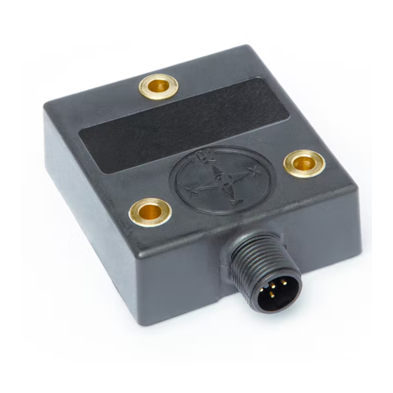
Avoid mechanical load! Mounting instructions IK360 is a pre-calibrated device, which can be put into immediate operation, upon simple and easy installation with a three point mount and setting of preset. Its compact design and installation "anywhere" makes it versatile. -
Page 7: Ik360 Software Configuration
IK360 (2 axis) IK360 Software Configuration The IK360 - Analog Inclinometer is a very flexible device and can be easily configured using the RS232 interface. Important factory settings Description Value Operational Mode Continuous Mode Resolution 0.01° - IK360 Output Transmission Rate... -
Page 8: Programmable Parameters
Configuration Mode This mode is primarily used for modifying configurations and the settings of IK360 using RS232 Interface. In this mode, the position value is transmitted only upon request and is active until a power cycle, software reset or the IK360 is switched to measurement mode. All settings saved in this level are stored in the EEPROM and permanently available also after power cycle. -
Page 9: Rs232 Digital Interface - Setup And Programming
RS232 Digital Interface – Setup and Programming The RS232 interface of IK360 gives flexibility to the Inclinometer by providing easily accessible direct positional values and a simple interface for setup and configuration. Hardware Setup 5.1.1 Accessories Required IK360 Inclinometer Preparation of IK360 RS232 ... -
Page 10: Connection Setup
5.1.4 Connection Setup IK360 Analog -> M12 Connector -> RS232 Connector -> PC RS232 Port Software Communication Setup Once the hardware is connected, the RS232 interface communication has to be setup using HyperTerminal or any other terminal programming client software. Communication with the sensor is done through a standardized RS232 interface. - Page 11 Step 2: The appropriate parameters for the RS232 interface communication and please click on Open to create a new terminal program for IK360 RS232 interface communication. COM Port Baud Rate Data Bits Stop Bits Parity Flow Control Power Off – Power On for getting a boot-up message on startup.
-
Page 12: Boot-Up Message Representation
Variable Numerical Values Numerical 0x2e 0x0d 0x0a Values IK360 (1 axis) Output Display: <D0……….D5 D6 D7> <CR> <LF> is a program analogy to indicate end of current line and start of a new line in a program. IK360 (2 axis) CHAR ASCII... -
Page 13: Table 1: Commands In Configuration Mode
<CR> = cariage return <SP> = Space After reset, the IK360 reboots in the measurement mode giving a startup/ boot-up message. See Table 2 for defined code transmission rates. See Table 3 for defined baud rates. . A reset of the baud rate to the default value is not possible. -
Page 14: Preset/Direction And Teach-In Mode
Preset/ Direction Mode (teach 0) The Preset/Direction mode is the default mode in which the IK360 operates. In this mode the user can set the origin of measurement (0° Reference Angle) at the current point and can also change the direction of measurement. The changes done in the RS232 mode also gets reflected in the analog output. -
Page 15: Teach-In Mode (Teach 1)
5.4.5 Teach-In mode (teach 1) This is the mode used for scaling the IK360 output as per the users’ requirement. The user can set the range of measurement and the IK360 analog output is scaled accordingly. The range of measurement is defined to lie within the origin and maximum angle positions, which then corresponds to the analog output scaling. - Page 16 Preset/Direction Mode, with the option of inversing direction with an analog input only if configured to do so in RS232. The IK360 has two analog inputs, SET1 and SET2 which can be used to configure in the IK360. To trigger/activate these functionalities (e. g. a Preset): ...
-
Page 17: Preset
SET1 and SET2. If the scaling was done correctly the IK360 should giva a (4 mA – 20 mA) or (0 V – 10 V) output in the range of measurement set between the locked positions of SET1 and SET2. -
Page 18: Analog Interface
Analog Interface The output signal from the IK360 analog interface can be directly connected to devices for immediate processing. The calibration of the signals can be easily done, since the signals are linear. Output Types 6.1.1 IK360 - Voltage Connect the corresponding (voltage analog output pin 5) open end of the connection cable to the measurement system. -
Page 19: Ik360- Current
(Note: R Load Direct Current Measurement Indirect Current Measurement Calculation of angle from IK360 (1 axis) current: Position angle (in °) = (I - 4 mA) / (0.0444 mA per °) For example: 1. -
Page 20: Ik360 - Analog Output Graphs
Calculation of angle from IK360 (2 axis) current: Position angle (in °) = (I - 12 mA) / (0.1 mA per °) 1. I = 8.31 mA Position Angle = (8.31 mA – 12 mA) / (0.1 mA per °) = -36.9°... -
Page 21: Ik360 (2 Axis ) X-Axis Voltage Output
IK360 (2 axis) X-Axis Voltage Output Angle (°) X-axis IK360 (2 axis) Y-Axis Voltage Output Angle (°) Y-axis IK360 (2 axis) X-Axis Current Output Angle (°) X-axis IK360-RS232 Date: 23.01.2017 Page 21 of 22 Art.no. 86152 Mod. Status 10/17... -
Page 22: Ik360 (2 Axis ) Y-Axis Current Output
IK360 (2 axis) Y-Axis Current Output Angle (°) Y-axis IK360-RS232 Date: 23.01.2017 Page 22 of 22 Art.no. 86152 Mod. Status 10/17...
Need help?
Do you have a question about the IK360 and is the answer not in the manual?
Questions and answers